

Tutorials
Jumper Wires Explained: Male to Male vs Male to Female
Aug
You never choose a jumper wire by preference — you read the two things you are joining, and the gender falls out on its own. A module with pins sticking out, going into an Uno’s sockets, needs male-to-female. Breadboard hole to breadboard hole needs male-to-male. Two pinned boards facing each other need female-to-female.
Which jumper wire does your project actually need?
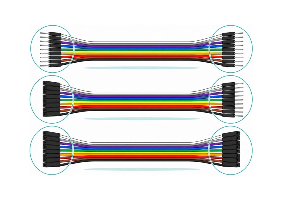
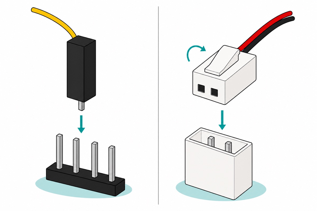
A jumper wire connection is a plug and a socket, never two plugs. A male end is a bare silver pin in a small black housing; a female end is that same housing with a hollow socket inside and no pin showing. Inside the female end is a folded spring strip that grips a 0.64 mm square post from two sides — which is why a male end has nothing for another male end to hold on to, and why two females have nothing to grip.
So look at each endpoint, decide whether it is a pin or a hole, and the wire supplies the opposite of both. The decision never depends on what the project does.
| What you are joining | Wire you need | Example from our shelves |
|---|---|---|
| Module’s male pins → Uno’s female sockets | Male-to-female | HC-SR04 straight to an Uno |
| Breadboard hole → breadboard hole | Male-to-male | Two rows of the same breadboard |
| Module’s male pins → breadboard hole | Male-to-female | Socket end onto the sensor’s pin, pin end into the board |
| Module already pushed into the breadboard → elsewhere on the board | Male-to-male | Its pins have become breadboard holes like any other |
| Module’s male pins → another module’s male pins | Female-to-female | A sensor wired direct to a display backpack |
| Uno’s header socket → breadboard hole | Male-to-male | Uno 5V feeding a breadboard power rail |
| Bare unfitted holes in a PCB | Solder a header first | NEO-6M GPS |
All three genders, 20 cm — the set that covers every job on this page
 40pcs Dupont Wire 10cm 20cm 30cm for Breadboard DIY Experiment Jumper Wire Breadboard wire - DUPONT WIRE M-M 20CM
 40pcs Dupont Wire 10cm 20cm 30cm for Breadboard DIY Experiment Jumper Wire Breadboard wire - DUPONT WIRE M-F 20CM
 40pcs Dupont Wire 10cm 20cm 30cm for Breadboard DIY Experiment Jumper Wire Breadboard wire - DUPONT WIRE F-F 20CM
Worth adding
 Breadboard Jumper Wire Set with Casing 140 pcs / 560 pcs For Arduino Prototyping Application - 140 PCS JUMPER WIRE KIT
 2.54mm Pin Header Female Male Single Row Header 40P Connector Black White Red Yellow Green Blue - 40P MALE HEADER (BLACK)
The 140-piece kit is rigid pre-formed solid-core wire in a case — it lies flat on a breadboard instead of arching over it, so a crowded board stays readable. The 40-pin male header strip is the crimp-free gender fixer: snap off a pin, push it into any female end, and that end is now male.
Twenty centimetres suits a board and a breadboard on the same desk; the same three genders come in 10 cm and 30 cm.
How do you tell a module’s gender from the product photo?
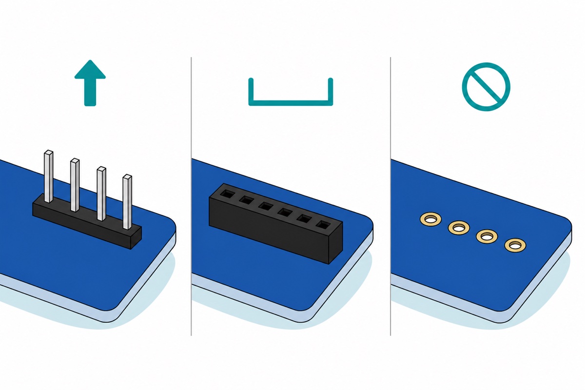
A module’s gender is decided at its edge, not in the middle of the board. Bare silver posts standing up out of a black plastic strip are male. A black block with a row of dark square openings is female. And a line of small gold-ringed holes drilled through the PCB with nothing fitted in them is neither yet — that board needs a header soldered in before any jumper touches it, which our header-soldering guide walks through.
Three worked examples from our own catalogue. The HC-SR04 ultrasonic sensor arrives with its four pins already soldered in and pointing up — male — which is exactly why our HC-SR04 build reaches an Uno with four male-to-female wires and no soldering iron. The LCD1602 I2C backpack carries a right-angle four-pin male header marked GND, VCC, SDA, SCL, so it wires the same way. The NEO-6M GPS ships with four bare plated holes and no header fitted, so soldering comes first.
An Uno’s headers are sockets all the way round, so anything reaching an Uno must present a male end there, whatever the sensor is.
What is the difference between Dupont and JST connectors?
Dupont is the 2.54 mm family every jumper wire belongs to: individual crimped contacts, each in its own small plastic housing, that you can pull off a wire and re-pin at will. Nothing latches and nothing is keyed — the contact holds by spring friction alone. That looseness is the point on a bench, where you rewire twenty times an evening.
JST is a family of wire-to-board plugs built for the opposite job: connect once, stay connected. The three you will meet are XH at 2.50 mm pitch, rated 3 A with AWG #22 wire and used on battery balance leads and modules; PH at 2.00 mm pitch, rated 2 A with AWG #24, the small-LiPo standard; and SM, the inline wire-to-wire pair that addressable LED strips ship with.
They do not interchange, and three separate things stop them. The pitch is close but wrong. XH steps 2.50 mm while Dupont steps 2.54 mm, so each position drifts 0.04 mm further out of line — a two-way plug barely notices, but by the tenth position the error has grown to 0.36 mm, over half the width of a 0.64 mm post, and the housing simply cannot sit down. The shroud is a key. JST headers are four-walled boxes around the posts, and that box exists so the plug goes on one way only; a Dupont housing is a bare block with nothing to stop it going on backwards, which is how a reversed battery lead happens. The latch is real. XH and PH housings click into the shroud; a Dupont end is held by nothing but the grip of its own spring.
One thing genuinely is shared, and it is why the bodge tempts people: a JST XH post is 0.64 mm square, the same as a 0.1 in header post, so one female Dupont socket really does seat on one XH pin. That is the whole overlap — nothing latches it, and a JST PH post is a finer 0.50 mm square, slim enough to drop through a 0.7 mm PCB hole and far too slim for a Dupont socket to grip. Use it to probe a pin, never to finish a build.
| Dupont 2.54 mm | JST XH | JST PH | |
|---|---|---|---|
| Pitch | 2.54 mm | 2.50 mm | 2.00 mm |
| Post | 0.64 mm square | 0.64 mm square | 0.50 mm square |
| Rated current | 3 A at the header; the wire is the limit | 3 A (AWG #22) | 2 A (AWG #24) |
| Polarized? | No — no key at all | Yes, shrouded | Yes, shrouded |
| Latched? | No, friction only | Yes | Yes |
| Re-pinnable by hand | Yes | With the right crimp tool | With the right crimp tool |
| Where you meet it | Breadboards, sensor modules, dev boards | Balance leads, solenoids, fans | Small LiPo packs |
Those ratings belong to the connector, not to the cable in your hand. A jumper is thin stranded wire crimped without solder into a spring clip you have re-plugged fifty times, and every friction contact adds resistance a soldered joint would not — resistance that leaves as heat and as volts lost between the supply and the load. A sensor or an I2C display draws tens of milliamps and never notices; a servo under load, a DC motor or the 12 V solenoid below pull amps. Feed those through a soldered or screw-terminal joint and let the jumper carry the signal only, or the board browns out the moment the motor turns — which reads as a code bug and never is.
Do you sell a JST-to-Dupont wire?
We do not stock a ready-made JST-to-Dupont adapter lead. Here is how we would make the join, in rising order of how much abuse it will take.
The header-pin trick. Snap two pins off a 40-pin male header strip and push them into the sockets of a female-ended jumper. You have just made a male end without a crimp tool, because a female Dupont socket is built to grip exactly that 0.64 mm post — and a female header strip does the reverse on a male end. It stays a signals-only trick: that loose pin is held by spring pressure alone, and it is a second unsupported joint in the path.
Cut and solder. Cut the JST tail 4 cm from its plug, solder each conductor to a jumper wire, and sleeve each joint separately in heatshrink, staggered rather than side by side, so the two can never touch. Our soldering guide covers the technique.
Screw terminals. A KF301 screw-terminal block takes bare stripped copper under a screw and gives you a joint that survives being pulled. This is the lane for anything that moves current rather than information. Our 12 V solenoid lock is the catalogue’s clearest JST tail, and belongs on screws. Before ordering housings for any JST tail, put a ruler across the plug and measure centre-to-centre: 2.5 mm means XH, 2.0 mm means PH. All of this is low-voltage DC — none of it belongs near mains wiring.
If you would rather crimp Dupont ends than solder, this shows the tool and the motion:
What are the three kinds of breadboard wire?
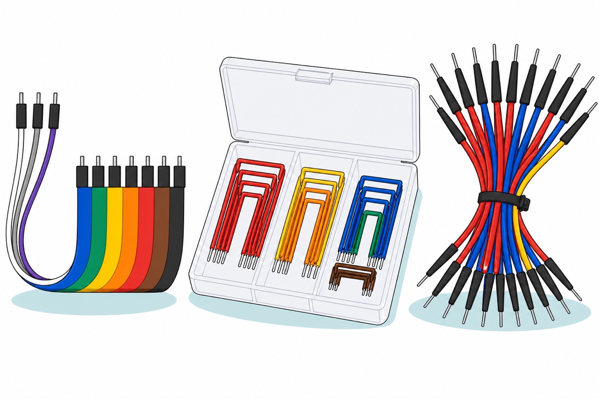
The flexible Dupont ribbon is what our packs are: 40 individual wires manufactured side by side in a rainbow strip, from which you peel off as many as you need. Forty wires — not forty pairs, and not one cable with forty cores. Peel them with intent: red for the positive rail, black for ground, every hop — the habit that stops a module being handed 5 V on its GND pin at midnight.
The rigid pre-formed kit is a different animal: the 140-piece set is solid-core wire cut and bent into flat U-staples, sorted by length and colour in a clear case, with bare tinned ends and no housings. Each one lies flat against the breadboard instead of arching over it, so a dense circuit stays readable — but it only fits breadboard holes, and it is not a Dupont substitute.
The male-to-male bundle such as this zip-tied set is flexible wire again, mostly red and blue, but with long tapered strain-relief boots instead of rectangular housings — the pin sticks out further, for deep breadboard holes.
Which cable should you put in the basket?
| Job in front of you | What to order |
|---|---|
| A module’s own pins to an Uno socket or a breadboard hole | M-F Dupont 20 cm |
| Breadboard hole to breadboard hole, or an Uno socket down to the board | M-M Dupont 20 cm |
| Two pinned modules joined directly | F-F Dupont 20 cm |
| Extending an M-F wire’s socket end to another socket | M-M Dupont as a bridge |
| Tidy, flat, permanent-looking breadboard layout | 140-piece rigid kit |
| Turning a female end male (or the reverse) | Male header strip / female header strip |
| A JST tail that has to carry real current | KF301 screw terminal |
How do you check a jumper wire you suspect is broken?
A Dupont crimp squeezes stranded copper without solder, so pulling a jumper out by the cable instead of by its black housing puts the whole load on those strands. A few of those and the wire is open inside an end that still looks perfect. That failure reads as a dead sensor. Push one end of the suspect wire into D2 and the other into D3, and let the Uno settle it.
// Jumper-wire tester. Uno. The wire under test has to present a MALE end
// at D2 and at D3, because the Uno's own headers are sockets: an M-M wire
// plugs straight in, an M-F wire needs one snapped-off header pin pushed
// into its socket, and an F-F wire needs two.
const uint8_t DRIVE_PIN = 3;    // held at 0 V: the far end of the wire
const uint8_t SENSE_PIN = 2;    // pulled up inside the chip: the near end

const unsigned long TEST_MS = 1000;   // how long you have to wiggle it

void setup() {
  Serial.begin(9600);
  pinMode(DRIVE_PIN, OUTPUT);
  digitalWrite(DRIVE_PIN, LOW);
  // INPUT_PULLUP ties this pin to 5 V through 20-50 kohm inside the AVR,
  // so it reads HIGH with nothing attached and LOW only if copper
  // actually reaches D3. No external resistor, no false readings.
  pinMode(SENSE_PIN, INPUT_PULLUP);
  Serial.println(F("Wiggle the wire at both crimps for one second."));
}

void loop() {
  unsigned long start = millis();
  unsigned int dropouts = 0;
  bool last = digitalRead(SENSE_PIN);

  while (millis() - start < TEST_MS) {
    bool now = digitalRead(SENSE_PIN);
    if (now && !last) dropouts++;   // the pull-up won: copper let go
    last = now;
  }

  if (dropouts > 0) {
    Serial.print(F("INTERMITTENT - dropouts this second: "));
    Serial.println(dropouts);       // a crimp barely holding the strands
  } else if (digitalRead(SENSE_PIN) == HIGH) {
    Serial.println(F("OPEN - nothing is getting through"));
  } else {
    Serial.println(F("GOOD - solid for a whole second"));
  }
  delay(500);
}
It compiles to 2,598 bytes, 8% of the Uno’s flash. The wiggling is the test, not the plugging in: a crimp that has lost half its strands still reads GOOD lying still, and reports dropouts the moment you flex it.
Common mistakes we see from real customers
Ordering by count instead of by end. One customer told us afterwards: “That day asked for one male to male and another one male to female but staff put both male to male.” One number, two packs, and nothing in the order named the ends. Write the endpoints down instead — “sensor pins to Uno sockets” — and the gender stops being a guess.
Assuming the cable is in the box. “is it come with cable?” and “does it come with a female connector” arrive most weeks. A sensor ships as the module and its own soldered header; wires are bought separately, which is why they come 40 to a pack rather than four to a sensor. Name the gender when you add a pack.
Reading “40 pcs” as forty of something else. “40 pcs ? untuk dupont wire female-female 20 cm?” — forty separate wires per pack, joined in a ribbon you peel apart.
Forcing a JST plug onto a Dupont header. The pitch is out and the shroud is in the way, so what gives is the plastic. Adapt the cheap end — the jumper — and leave the plug on the part you paid for.
FAQ
What is the difference between male-to-male and male-to-female jumper wires?
A male end is a bare pin, a female end is a socket that receives one. Male-to-male carries pins at both ends, which is what a breadboard needs. Male-to-female carries a socket for a module’s pin and a pin for the Uno’s socket.
Which jumper wires do I need for an Arduino Uno?
An Uno’s headers are sockets, so every wire reaching it needs a male end there. Straight from a pinned sensor that means male-to-female. From a breadboard hole up to the Uno it is male-to-male, and a module sitting beside the board rather than pushed into it still needs male-to-female to reach a hole.
Do you sell a JST-to-Dupont wire?
Not as a ready-made lead. Push male header pins into a female jumper end for signals, cut and solder the JST tail for a permanent join, or land it in a KF301 screw terminal when it carries real current.
How many wires are in one Dupont pack?
Forty individual wires, made side by side as a peelable rainbow ribbon. Peel off what you need; the rest stay joined, tidy and colour-ordered.
Can I turn a female jumper end into a male one?
Yes — snap one pin off a 2.54 mm male header strip and push it into the socket, which is built to grip exactly that 0.64 mm post. Fine for signals; solder or a screw terminal is better for current.
Last updated August 2026. Stuck? Chat with us on WhatsApp.

Pingback: Crocodile Clip Test Leads: When to Use Them
Pingback: How to Build a 4-Servo Robot Arm with Arduino Uno
Pingback: Breadboard Guide: Hidden Holes, Mini vs 400 vs 830
Pingback: ESP32 Expansion Board: Do You Need One? 30-Pin Shield