

Tutorials
Relay Module with Arduino & ESP32 — Wiring It Safely
May
A relay module lets a small Arduino or ESP32 signal switch a completely separate circuit — a 12V fan, a 5V pump, an LED strip. Wire the control side to 5V, GND and one GPIO, put the load on COM and NO, and learn on low-voltage DC before ever considering 240V mains. This guide covers the exact board MakerHub sells — including the HIGH/LOW trigger jumper behind most inverted-relay confusion.
What does a relay module actually do?
A relay module is an electrically operated switch: a coil pulls a contact from one position to the other, and an on-board opto-coupler and driver transistor let a microcontroller pin control that coil safely. The relay block on MakerHub’s boards is the blue Songle SRD-05VDC-SL-C, whose 5V coil draws about 71mA when energised — far more than a GPIO pin should supply, which is exactly why the module exists.
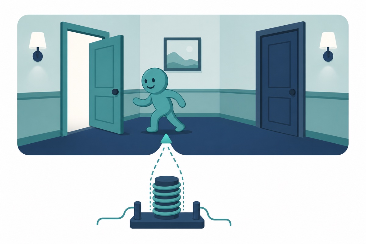
The three output terminals make sense as a hallway with two doors:
| Terminal | Meaning | State when the relay is idle |
|---|---|---|
| COM | Common — the moving contact | Always part of the circuit |
| NO | Normally Open | Disconnected — load is OFF until the coil energises |
| NC | Normally Closed | Connected — load is ON until the coil energises |
For almost every project you want COM plus NO, so the load sits dead until your code turns it on. The relay is single-pole double-throw (SPDT): COM always touches exactly one door, never both.
Which relay module should you buy?
The 1-channel and 2-channel relay modules below are the same circuit — same red PCB, screw terminals, opto-coupler, indicator LEDs and trigger-select jumper — so pick by how many loads you switch. The Arduino Uno compatible (CH340G) drives either happily.
If you want the relay to switch itself off after a set delay instead of waiting for a microcontroller to tell it to, that is a different board — our 12V timer relay module guide covers the wiring and how to set the time.
Parts list
 Arduino Uno Compatible SMD UNO R3 with Type B Cable - ATMEGA328P with CH340G-Microcontroller Project
 Relay Module 3.3V 5V 12V 1/2/4/8 Ways Optocoupler Trigger Relay Module 1 2 4 8 Channel Relay Module - 5V RELAY MODULE(1WAY)
 Relay Module 3.3V 5V 12V 1/2/4/8 Ways Optocoupler Trigger Relay Module 1 2 4 8 Channel Relay Module - 5V RELAY MODULE(2WAY)
What is the HIGH/LOW trigger jumper for?
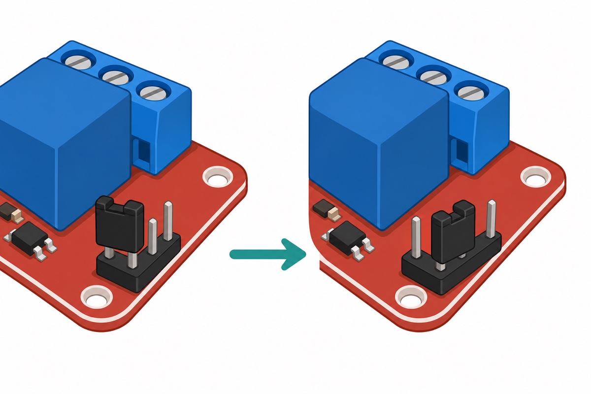
The HIGH/LOW trigger jumper — a small black cap on a three-pin header marked H and L — decides which logic level pulls the relay in. In the L position the board is low-level triggered: the relay energises when IN is pulled LOW; in the H position it energises when IN is driven HIGH.
Most online tutorials assume the older fixed active-LOW boards, so their sketches run inverted on a board jumpered to H — and the factory position varies between batches. Never assume; look at where the cap sits on your board.
One-minute test before wiring any load: leave the output terminals empty, power the board, toggle IN from your sketch, and watch the channel LED while listening for the click. If it behaves opposite to your code, move the jumper or swap the ON/OFF constants — with nothing connected, an inverted relay costs nothing.
How do you wire a relay module to an Arduino Uno?
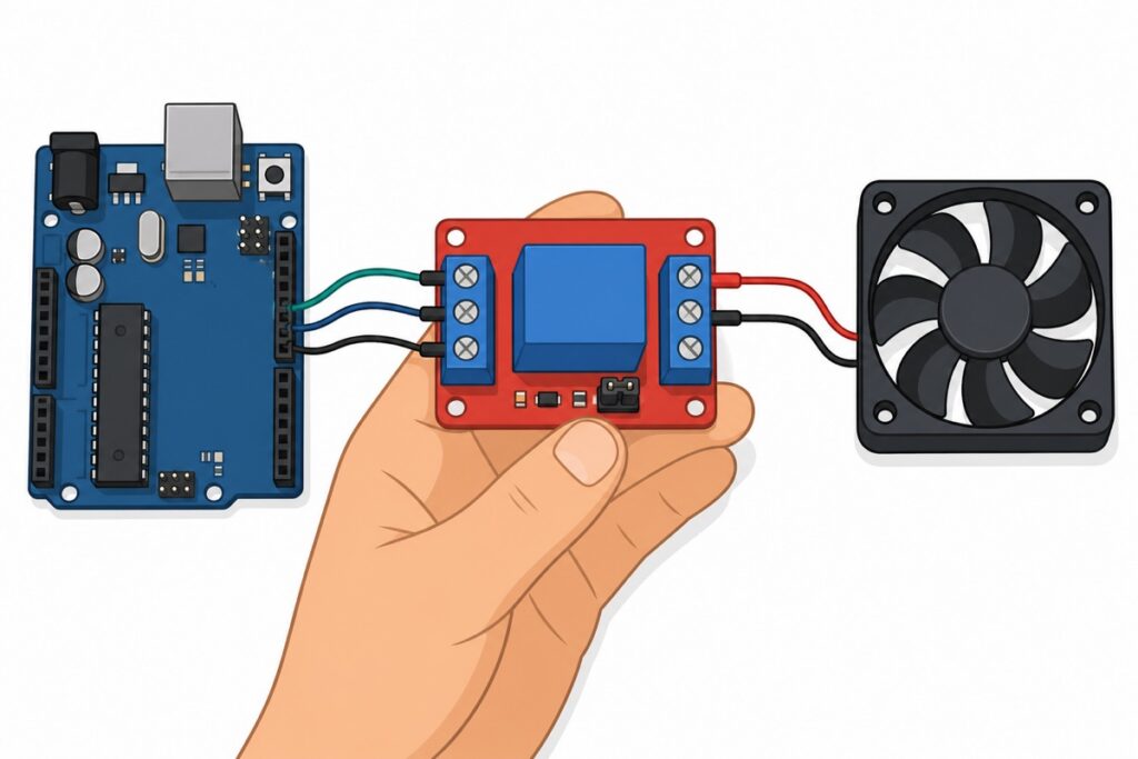
The relay module pinout is six screw positions: DC+, DC− and IN on the control side, NO, COM and NC on the output side — screw terminals on both edges, not header pins. IN only drives the opto-coupler’s LED — a 15–20mA load per channel — while the coil’s ~71mA comes from DC+; an Uno GPIO is only rated for 20mA per pin, which is why the coil never hangs off a pin.
| Relay terminal | Arduino Uno | Purpose |
|---|---|---|
| DC+ | 5V | Coil and opto power (~71mA per energised coil) |
| DC− | GND | Ground |
| IN | D7 | Trigger signal (15–20mA, opto input) |
Start with a low-voltage load — a 12V fan with its own supply is perfect; the same pattern drives the 5V pump in our automatic plant watering build.
| From | To | Note |
|---|---|---|
| 12V supply (+) | Relay COM | The supply enters the switch |
| Relay NO | Fan red wire | NO keeps the fan off by default |
| Fan black wire | 12V supply (−) | Completes the load loop |
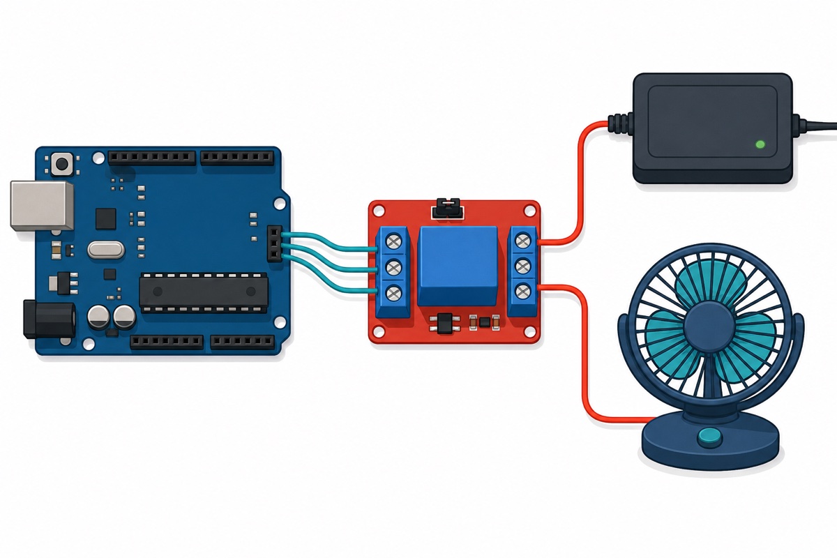
The sketch below works on either jumper setting — set the two constants to match your board:
// Relay module + Arduino Uno — switching a 12V fan
// Control side: DC+ -> 5V, DC- -> GND, IN -> D7
// Load side: 12V supply (+) -> COM, NO -> fan (+), fan (-) -> supply (-)

const int RELAY_PIN = 7;

// Match these to YOUR trigger jumper position:
// Jumper on L (low-level trigger):  relay ON when pin is LOW  (use LOW / HIGH)
// Jumper on H (high-level trigger): relay ON when pin is HIGH (use HIGH / LOW)
const int RELAY_ON  = LOW;
const int RELAY_OFF = HIGH;

void setup() {
  digitalWrite(RELAY_PIN, RELAY_OFF);  // define the OFF state before the pin drives
  pinMode(RELAY_PIN, OUTPUT);
}

void loop() {
  digitalWrite(RELAY_PIN, RELAY_ON);   // fan on for 5 seconds
  delay(5000);
  digitalWrite(RELAY_PIN, RELAY_OFF);  // fan off for 5 seconds
  delay(5000);
}
Can an ESP32 trigger a 5V relay module with 3.3V?
The ESP32’s 3.3V logic triggers these 5V opto boards reliably in practice: feed DC+ from the dev board’s 5V/VIN pin, share GND, and drive IN straight from a 3.3V GPIO. The opto-coupler only needs enough current to light its internal LED, and 3.3V is normally enough for this style of board.
Two honest caveats. Never power DC+ from the 3.3V pin — the coil is wound for 5V. And opto input resistors vary between batches, so run the no-load click test before trusting a new board; the odd batch prefers a true 5V trigger. Our ESP32 vs ESP8266 vs Uno comparison covers the 3.3V-vs-5V logic story properly.
Once the board clicks reliably, the ESP32 can take its orders over Wi-Fi: from a web page the ESP32 serves itself, or from your phone through Blynk.
Can this relay module switch 240V mains?
The Songle relay’s contacts are printed 10A 250VAC / 10A 30VDC, and that rating is real — but it describes the sealed blue relay block, not the bare module as a finished product. The module has exposed screw terminals, no enclosure, and no creepage-engineered layout for humid Malaysian conditions, so on its own it is a component, not an appliance switch. The datasheet’s own tables are also more conservative than the case printing:
| Rating | Where it appears | What it means for you |
|---|---|---|
| 10A 250VAC / 10A 30VDC | Printed on the relay case | Certified ceiling for the contacts themselves |
| 10A 125VAC / 7A 240VAC / 7A 28VDC | Datasheet, Form C resistive load | At Malaysia’s 240V, plan around 7A — not 10A |
| 3A (cosΦ=0.4, at 120VAC/28VDC) | Datasheet, inductive load — no 240VAC inductive figure is published at all | Motors, pumps and solenoids get a much lower budget |
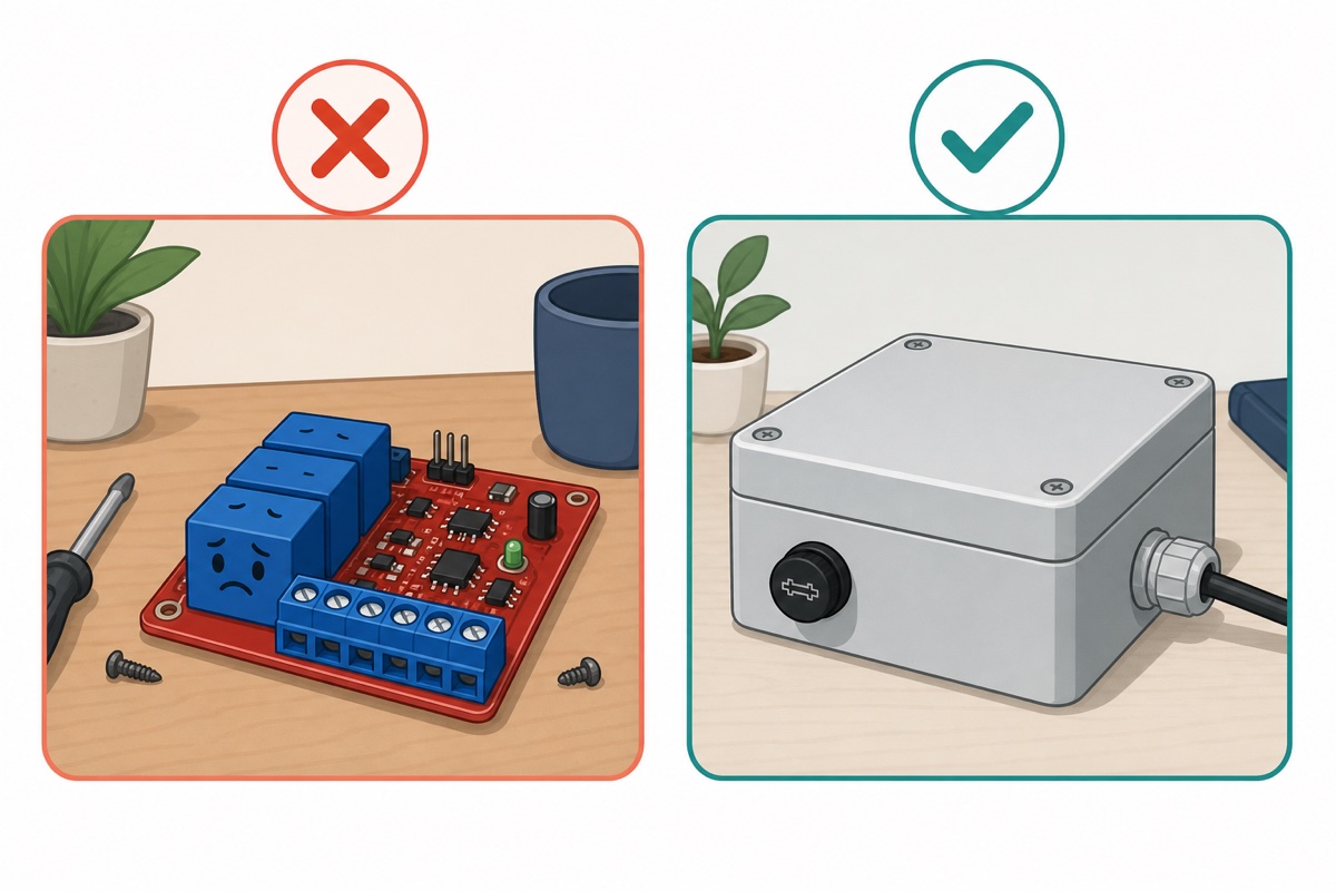
There is also a legal layer: under Malaysia’s Electricity Regulations 1994, even a house’s single-phase wiring must be carried out under the supervision of a competent person registered with Suruhanjaya Tenaga — a licensed wireman or electrical contractor. Permanent 240V wiring is their job, not a weekend experiment.
If a project genuinely needs to switch a mains appliance, the adult version is: enclosed, fused, correctly-rated cable, terminals never touched while energised — and a qualified person building or checking the mains portion. We deliberately do not publish a 240V walkthrough; practise the logic on 12V, where mistakes are lessons instead of emergencies. This video is a sober look at what switching AC involves:
Why do motors and solenoids need extra care?
Motors, pumps, solenoids and transformers store energy in their magnetic field, and when the relay contacts open that energy arcs across the gap. Arcing pits and eventually welds contacts, which is why the datasheet drops the inductive rating to 3A. Stay well under the printed rating; add a flyback diode across a DC inductive load, and on AC an RC snubber across the contacts tames the arc. (The module’s coil already has its own diode — this note is about the load you switch.)
Common mistakes we see from real customers
Assuming active-LOW because a tutorial said so. The classic relay-works-backwards report is almost always the trigger jumper sitting on the opposite setting from the sketch’s constants. Check the jumper first, code second.
Wiring the load to NC instead of NO. The symptom is a load that runs the moment power arrives and shuts off when the code says on. Move the wire from NC to NO; a multimeter on continuity mode across COM and each terminal shows the difference in seconds.
Feeding DC+ from a 3.3V pin. The relay chatters, buzzes, or never clicks. The opto input tolerates 3.3V; the coil does not — DC+ always gets 5V.
Clamping insulation in the screw terminal. Screw terminals grip whatever you feed them, including plastic. Strip 5–6mm of copper, insert fully, tighten, then tug-test every wire — an insulation-clamped joint works on the bench, then fails later.
Switching a motor at the full printed rating. 10A is the resistive ceiling, not a motor budget. Inductive loads get 3A and a snubber, or a properly oversized relay.
FAQ
Do I need a separate power supply for the relay module?
For one or two channels on an Uno’s 5V rail, no — budget about 71mA per energised coil. If several relays hold in at once, or the board browns out when the relay clicks, give DC+ its own 5V supply and keep the grounds joined.
Can I power this 5V relay module from 12V?
No. The coil is wound for 5V, and the datasheet caps the coil at 120% of nominal — 6V. On a 12V system, step the supply down to 5V for DC+ and keep the load’s 12V on the contact side, where it belongs.
Is it safe to switch a kettle or rice cooker with this module?
Not as a bare board on the desk. Mains appliances are a 240V job: enclosed, fused, correctly-rated cable, and wiring done or checked by a licensed wireman as Malaysia’s regulations require. Build the same logic on a 12V load first — the code transfers exactly.
What is the difference between the 1-channel and 2-channel modules?
Per channel they are the same circuit — same Songle relay, opto input, trigger jumper, screw terminals. The 2-channel board adds a second relay block and an IN2 terminal, and needs the ~71mA coil budget counted twice when both hold in.
Last updated August 2026. Stuck? Chat with us on WhatsApp.

Pingback: Ultrasonic Mist Maker Module: DIY Humidifier Build
Pingback: Water Level Sensor for a Water Tank: Automatic Pump Control
Pingback: Rocker, Toggle or Push Button: Choosing an On/Off Switch for Your Project
Pingback: ESP-01S Wi-Fi Relay Module: How to Flash It and Wire a Load
Pingback: Mini Water Pump 3V-5V: How to Choose and Drive It