

Tutorials
ESP-01S Wi-Fi Relay Module: How to Flash It and Wire a Load
Sep
The ESP-01S Wi-Fi relay module is a carrier, not a finished device: a socket, a 5 V relay, a regulator and two screw terminals. It ships without the ESP-01S module, and stays silent until you flash that module with firmware of your own. The carrier has no second microcontroller and no serial pins, so the module’s factory AT firmware has nobody to talk to.
What is the ESP-01S Wi-Fi relay module, and what is on the board?
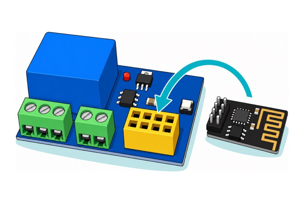
The ESP-01S Wi-Fi relay module is sold under half a dozen names — Wi-Fi relay switch, smart relay board, remote relay module, DC Wi-Fi switch, home automation module — and all of them describe one idea: a relay whose coil is commanded over Wi-Fi instead of by a finger on a wall switch. The carrier that does it here is a blue board about the size of a large postage stamp carrying five things: a blue cube relay marked SRD-05VDC-SL-C, a PC817 optocoupler, an AMS1117-3.3 regulator, a yellow 2×4 socket for the module, and two green screw-terminal blocks — two pins for 5 V in, three for the relay’s own contacts.
What is absent matters more. No second microcontroller, no pin header besides that socket, no USB port. The relay coil is driven from one of the module’s own GPIO pins through the optocoupler, so with the socket empty nothing here can decide anything. The white button on the edge is RST, which restarts the module. It is not a flash button, and there isn’t one.
The carrier, the brain that plugs into it, and the tool that programs it
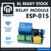 ESP-01S WiFi Relay Module Remote Control Switch Smart Home Automation IoT Development Board ESP8266 5V DC
 ESP01S ESP8266 Wireless Transceiver WIFI internet Module Low Power Consumption- ESP-01S - Arduino IOT - ESP-01S
 ESP01S ESP8266 Wireless Transceiver WIFI internet Module Low Power Consumption- ESP-01S - Arduino IOT - ESP-01S DOWNLOADER
 Power Supply Adapter DC Universal AC to DC Converter PSU 5V2A 5V3A 9V2A 12V2A - P.S. ADAPTOR (5V3A)
 5.5x2.1mm DC Power Male Connector Plug Jack Adapter for Arduino DIY Electronics Projects - 5.5x2.1 DC CONNECTOR (F)
The other road, if one relay is not enough
 NodeMCU ESP32 Wi-Fi + Bluetooth Development Board CH340/CP2012 - For IOT Project - ESP-32 (CH340)
 Relay Module 3.3V 5V 12V 1/2/4/8 Ways Optocoupler Trigger Relay Module 1 2 4 8 Channel Relay Module - 5V RELAY MODULE(1WAY)
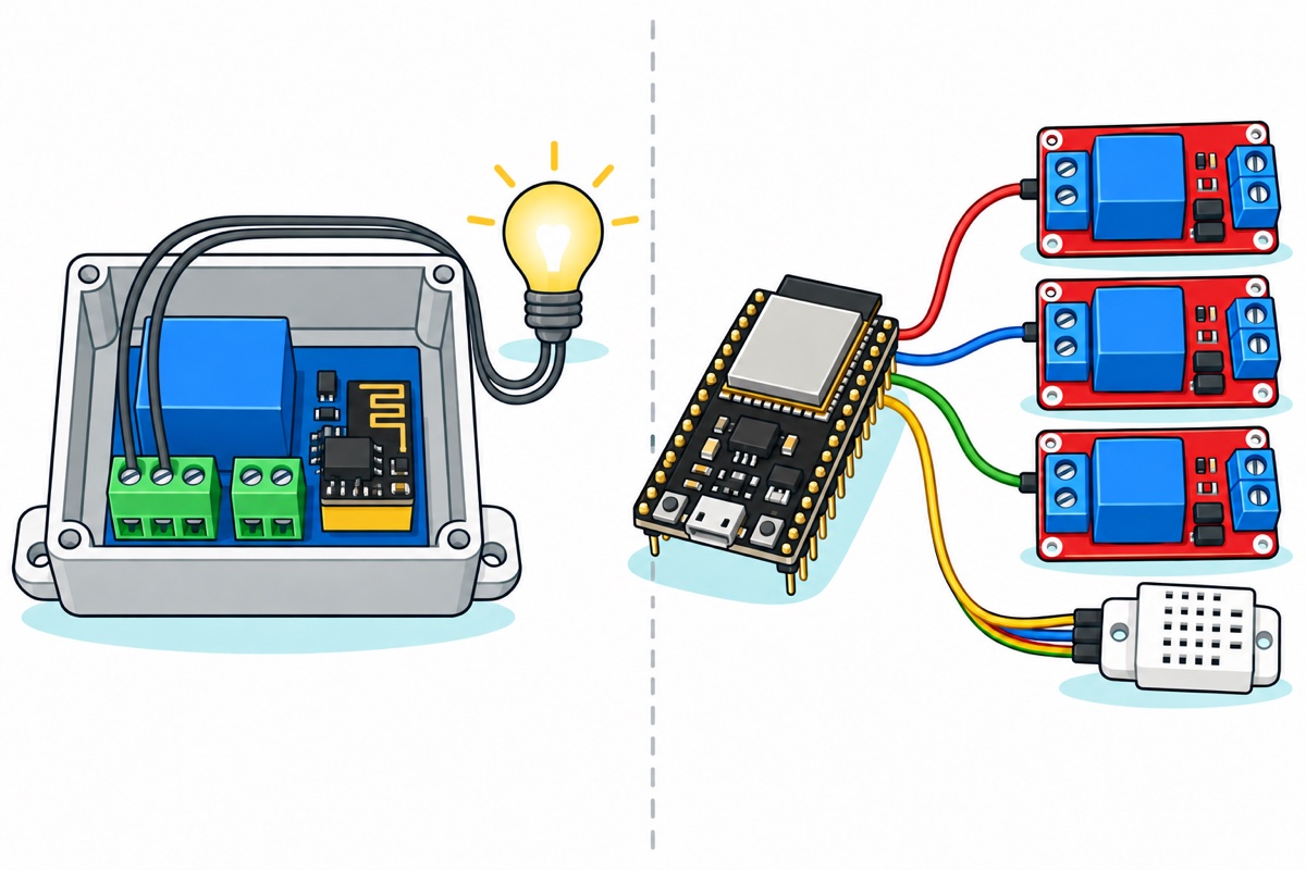
This is the other road, not an add-on to the kit above. If you already know you want two or more switched channels, or a sensor sitting next to the relay, skip the ESP-01S entirely and build on an ESP32 with a separate relay module — the reasoning is in the last section.
Why does the board do nothing out of the box?
The ESP-01S leaves the factory running Espressif’s AT firmware, a serial command interpreter: something else sends it text over the UART, and it answers. That is useful when the module sits beside an Arduino with two wires between them. On this carrier it cannot work, because the carrier connects TX and RX to nothing. Once the module is seated, the only route in is Wi-Fi — and answering over Wi-Fi means running code of your own.
There is a second family of ESP-01S relay carriers that does answer AT commands, and it explains why so many tutorials show a byte string like A0 01 01 A2 flipping a relay: those boards add a small eight-pin STC microcontroller that sits on the module’s TX line and decodes that string itself. This carrier has no such chip — beside the socket there is a four-pin PC817 optocoupler, the AMS1117-3.3 regulator and one small transistor, and nothing with eight legs on it — so nothing on the board is listening, and the relay has to be driven by the module.
| Route | What you actually do | Verdict for this board |
|---|---|---|
| AT firmware, as shipped | Send AT text commands over the serial pins | Dead end here — no serial wires on the carrier and no on-board chip listening |
| ESP8266 Arduino sketch | Write one file in the Arduino IDE and upload it once | Start here. One toolchain, one file, everything visible |
| Tasmota or ESPHome | Flash ready-made smart-home firmware, then set GPIO0 as an inverted relay in its web UI | Real and well supported — a published template exists — but a second toolchain to learn first |
Take the middle route first. Starting with Tasmota means debugging two unfamiliar things at once — the flashing ritual below and somebody else’s configuration model — with no way to tell which is failing. Flash a short sketch, hear the click, then decide.
How do you put an ESP-01S into flash mode with no flash button?
The ESP8266 decides what to do in the instant it comes out of reset by reading three strapping pins, and the one an ESP-01S leaves you to move is GPIO0: GPIO2 is brought out as well but has to stay high, and GPIO15 is not brought out at all. High at reset means run the firmware already in flash; low means wait for new firmware over the UART. The chip reads that pin once and commits — nothing a second later changes its mind. That is the whole ritual: hold GPIO0 down, apply power, let go, upload.
| Socket pin | ESP-01S function | Why it matters here |
|---|---|---|
| 1 | GND | One half of the flash-mode bridge |
| 2 | GPIO2 | Must be high at reset; the only genuinely spare pin |
| 3 | GPIO0 | Boot mode at reset, relay drive for the rest of the time |
| 4 | RX | Firmware comes in here |
| 5 | VCC | 3.3 V only — 5 V here destroys the module |
| 6 | RST | Reset, pulled low momentarily to restart |
| 7 | CH_PD / EN | Must be high, or the chip never wakes |
| 8 | TX | Progress and boot messages go out here |
The ESP-01S downloader is a black USB-A stick carrying the same yellow socket, a CH340 USB-serial chip and one conspicuous 1000 µF capacitor. That capacitor is the part worth understanding: Espressif’s ESP8266EX datasheet puts an 802.11b transmit burst at 170 mA against an 80 mA average, and a USB port feeding a thin PCB trace sags on a step like that. The cap supplies the burst locally — which is why adapters without one give uploads that fail halfway and modules that reboot the moment Wi-Fi starts.
The downloader carries no flash-mode switch, so you make the bridge yourself. The socket’s eight pins come through to solder tails on the underside of the stick: touch a wire, or a pair of tweezers, across the GND and GPIO0 tails while you push the USB plug into the port, and let go once it is seated. Builders who flash these often solder a small pushbutton across those two tails once and stop thinking about it.
Identify those two tails before you touch anything, because VCC comes through to the same underside and shorting it to GND collapses the 3.3 V rail instead of arming the bootloader. The eight tails are two rows of four, in the order the table above lists them: GND, GPIO2, GPIO0 and RX along one row, then VCC, RST, CH_PD and TX back along the other. GND and GPIO0 are therefore the first and third tails of one row, with GPIO2 untouched between them, and VCC is the corner diagonally opposite GND. To confirm that rather than count it, plug the empty downloader in, clip a black meter probe to one corner tail and touch the red probe to the corner diagonally opposite: about +3.3 V means the black probe is sitting on GND, and a reading near zero means you have the other diagonal — move to the remaining pair.
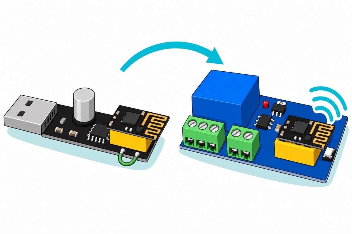
Seeing the physical sequence once helps, since the timing is the whole trick:
In the Arduino IDE, paste http://arduino.esp8266.com/stable/package_esp8266com_index.json into File → Preferences → Additional Boards Manager URLs, install esp8266 by ESP8266 Community from the Boards Manager, then choose Generic ESP8266 Module, upload speed 115200. Set Flash Size to 1MB (FS:64KB OTA:~470KB) — the ESP-01S’s flash chip is a 25Q80, and 8 megabits is one megabyte. The downloader is a CH340 device, so if no port appears the driver is the first suspect: our guide to a board that will not show up as a port covers it, as it does the CH340 serial cable.
What goes into the sketch?
Two facts shape every ESP-01S relay sketch. The first is that the coil hangs on GPIO0 through the PC817, and the carrier wires that optocoupler to invert: its internal LED sits between the 3.3 V rail and GPIO0, so the pin has to be pulled low before any current flows through it. That lights the LED, which turns the optocoupler’s output transistor on, which turns on the transistor holding the relay coil. The board’s published v4.0 schematic draws it exactly that way. So LOW closes the contact and HIGH lets it fall open.
The second follows from the first. GPIO0 is high at reset — that is the requirement for booting your firmware at all — and high is the open position on an inverting board. Every power-up, reset and re-flash therefore leaves the load switched off, which is the reason it belongs on the NO contact rather than NC.
// ESP-01S Wi-Fi relay - one switch, reachable from any browser on your LAN.
// Board: "Generic ESP8266 Module", Flash Size "1MB (FS:64KB OTA:~470KB)".
//
// The relay coil hangs on GPIO0 through the carrier's optocoupler, whose LED
// sits between the 3.3 V rail and GPIO0: pulling GPIO0 LOW lights it, which
// turns the transistor on, which energises the coil. So LOW = contact closed.
// If your carrier switches the other way round, swap the two lines marked below.
//
// No Serial here on purpose: once the module is seated in the carrier, TX and
// RX go nowhere, so the sketch has to announce itself over the network instead.

#include <ESP8266WiFi.h>
#include <ESP8266WebServer.h>
#include <ESP8266mDNS.h>

const char* WIFI_SSID = "your-wifi-name";
const char* WIFI_PASS = "your-wifi-password";
const char* HOSTNAME  = "mh-relay";     // reachable as http://mh-relay.local/

const uint8_t RELAY_PIN    = 0;         // GPIO0 - also the boot-mode pin
const uint8_t RELAY_CLOSED = LOW;       // level that CLOSES the contact
const uint8_t RELAY_OPEN   = HIGH;      // level that lets it fall open

ESP8266WebServer server(80);
bool relayOn = false;

void applyRelay() {
  digitalWrite(RELAY_PIN, relayOn ? RELAY_CLOSED : RELAY_OPEN);
}

void handleRoot() {
  String page = F("<!DOCTYPE html><html><head><meta name='viewport' "
                  "content='width=device-width,initial-scale=1'>"
                  "<title>Relay</title></head><body style='font-family:sans-serif'>");
  page += relayOn ? F("<h2>Relay: ON</h2>") : F("<h2>Relay: OFF</h2>");
  page += F("<p><a href='/on'>Turn on</a> | <a href='/off'>Turn off</a></p>"
            "</body></html>");
  server.send(200, "text/html", page);
}

void redirectHome() {
  server.sendHeader("Location", "/");
  server.send(303, "text/plain", "");
}

void handleOn()  { relayOn = true;  applyRelay(); redirectHome(); }
void handleOff() { relayOn = false; applyRelay(); redirectHome(); }

void setup() {
  // Park GPIO0 at the open level in the same breath as making it an output,
  // so the contact does not sit closed while Wi-Fi is still connecting.
  pinMode(RELAY_PIN, OUTPUT);
  applyRelay();

  WiFi.mode(WIFI_STA);              // station only - do not leave an open AP up
  WiFi.hostname(HOSTNAME);
  WiFi.begin(WIFI_SSID, WIFI_PASS);
  while (WiFi.status() != WL_CONNECTED) {
    delay(500);
  }

  MDNS.begin(HOSTNAME);             // if .local fails, read the IP off your router
  MDNS.addService("http", "tcp", 80);

  server.on("/", handleRoot);
  server.on("/on", handleOn);
  server.on("/off", handleOff);
  server.begin();
}

void loop() {
  MDNS.update();
  server.handleClient();
}
That builds to roughly 322 KB, comfortable inside the ESP-01S’s one megabyte. Unplug the downloader and move the module into the carrier’s yellow socket. It fits both ways round and only one is right: reversed, the socket lands 3.3 V on the module’s GND pin. The same corner-to-corner check settles it — with the 5 V supply of the next section connected and the socket still empty, the two diagonally opposite holes read about 3.3 V, and the hole the black probe sits on for a positive reading is the one that must take the module’s GND pin.
Two things go wrong at first boot and neither is the board’s fault. The ESP8266 is a 2.4 GHz-only radio, and the while loop in setup() waits forever without saying so: most home routers here publish one SSID for both bands and steer clients between them, so a module handed the 5 GHz half never associates and simply sits there. Give the 2.4 GHz band its own name in the router and point the sketch at that. The other is the address — stock Windows and some Android builds do not resolve .local names, so open the router’s client list, find mh-relay and use the IP it was given. Either way the page has no password: anyone already on your Wi-Fi can toggle the relay, which is fine for a lamp and not fine for a gate.
How do you wire the 5 V supply and the load?
The ESP01RM’s two-pin block wants 5 V, and the AMS1117-3.3 on the board is the reason it is not 3.3 V. A linear regulator can only subtract: Advanced Monolithic rates the AMS1117 to operate down to about 1 V of input-to-output difference, with dropout guaranteed no worse than 1.3 V at its 0.8 A test current and falling at lighter loads. Feed 3.3 V into that terminal and there is no headroom left to work with: the 3.3 V rail sags toward the 2.5 V floor Espressif gives the ESP8266EX just as the radio pulls hardest — and the 5 V coil would never pull in either.
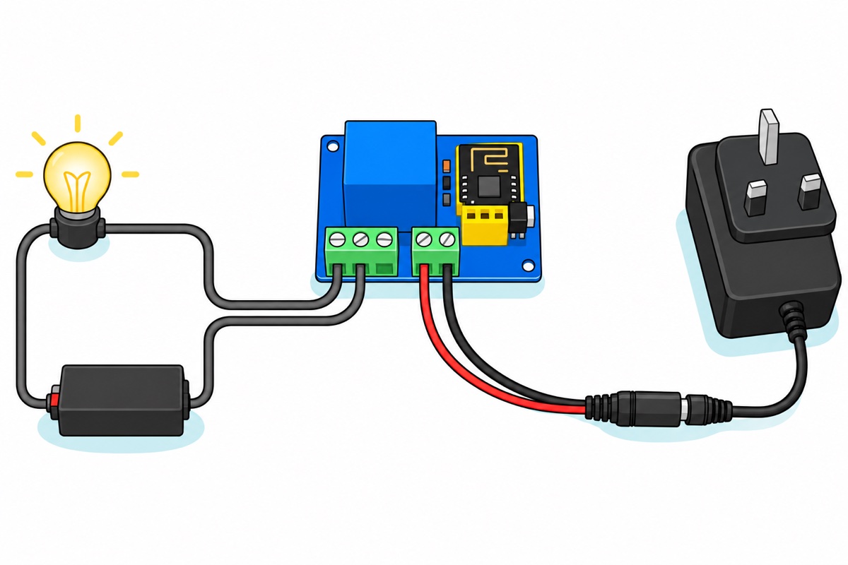
Add up what that rail carries. The Songle SRD-05VDC-SL-C coil is a 70 Ω, 0.36 W winding — about 72 mA at its rated 5 V — and the module peaks at 170 mA on transmit: a quarter of an amp at the worst moment. A 5 V 3 A adapter is far clear of it, with headroom to stop the rail dipping when coil and radio pull together. Its barrel plug lands in a 5.5 x 2.1 mm female pigtail whose stripped red and black ends go straight into the screw terminal — no charger cable gets cut. Meter it first: red should read positive against black.
| Terminal | Connect to | What it does |
|---|---|---|
| 2-pin block, + | Red lead of the 5 V pigtail | The board’s only supply — it feeds the AMS1117-3.3, the module and the relay coil |
| 2-pin block, − | Black lead of the pigtail | Common ground for coil and module |
| 3-pin block, COM | One side of the load’s own circuit, cut open | The moving contact |
| 3-pin block, NO | The other cut end of that same wire | Open at rest, closes when GPIO0 goes LOW. Use this one. |
| 3-pin block, NC | Leave empty | Closed at rest — the load would be live through every reset and re-flash |
The contacts are a switch, not a supply — nothing comes out of them. The load keeps its own power source, and the two contact screws stand in for a manual switch in its circuit. Our guide to wiring a relay module safely covers flyback and inductive loads.
Printed on the side of the cube are the contact ratings: 10A 250VAC, 10A 125VAC, 10A 30VDC and 10A 28VDC. Those numbers describe two pieces of metal sealed inside plastic, and say nothing about the board around them — an open PCB with the low-voltage side millimetres from the contact screws, no earth and no enclosure. Treat it as a low-voltage DC project board: a 12 V strip, a small pump, a doorbell chime. For 240 V mains the line from our delay timer relay wiring guide holds unchanged — fixed mains work in Malaysia belongs to an Energy Commission registered contractor, and a contact rating is not an enclosure.
Common mistakes we see
Buying the carrier alone and waiting for Wi-Fi. An empty socket holds no radio and no logic, so nothing appears on the network — and the board will not light up to reassure you either. Its one indicator LED sits across the relay coil and comes on only when the contact is actually pulled in, so a powered carrier with an empty socket is meant to look dark.
Trying to upload with the module still in the carrier. There is no USB port and no serial header there, and GPIO0 is committed to the relay. The module comes out, gets flashed in the downloader, and goes back.
Putting 12 V into the two-pin block because that was the adapter to hand. That terminal is the whole board’s supply and it is a 5 V input. The AMS1117-3.3 is a linear regulator, so every volt above 3.3 leaves as heat in one small surface-mount package with no heatsink: 5 V in means 1.7 V of drop, 12 V in means 8.7 V — five times the heat for the same current, on a board the size of a stamp with a relay coil sitting beside it.
Running the load from the same adapter that powers the board. Switch a strip or a pump on the very rail the carrier lives on and its inrush drags that rail down, the module browns out and resets, GPIO0 returns to its high idle and the contact opens — which lets the rail recover, so it closes again. That chatter is a shared supply, not a faulty board.
So which one should you buy?
The ESP-01S relay carrier is the right answer when the whole job is one switch in a small box — a light, a fan, a pump — reached from a phone on the same Wi-Fi.
Its ceiling is structural, not a matter of taste. The ESP-01S brings out four usable pins, two of which are the UART. GPIO0 is spoken for by the relay, leaving GPIO2 — itself a boot strap that must sit high at reset, so anything hung on it must respect that. One channel, no sensor, no display.
So the moment you want a second channel, a sensor beside the relay, or a screen, buy an ESP32 dev board and a separate relay module: pins to spare, and a USB port that flashes with no bridging ritual. Our ESP32 web server relay guide is this same build with room to grow, and the Blynk version adds a phone app and control from outside the house. If the chip is still open, our ESP32 vs ESP8266 vs Uno comparison settles that first.
FAQ
Does the ESP-01S relay module come with the ESP-01S?
No. The relay board is the carrier — relay, regulator, optocoupler, socket and terminals — and the ESP-01S is bought alongside it. That is why the yellow socket is empty in the product photo, and the commonest reason a new board seems dead.
Can I control the relay with AT commands?
Not on this carrier. AT firmware answers text sent over the module’s serial pins, and the carrier wires TX and RX to nothing — no header, no on-board microcontroller listening. Flash the module with your own sketch, or Tasmota, and it drives the relay itself.
Do I need the ESP-01S downloader, or will an ordinary USB-to-TTL cable do?
Use the socketed downloader. A general CH340 serial cable brings out 5 V, GND, TX and RX — no 3.3 V lead — while the ESP-01S is a 3.3 V-only part that also wants a stiff supply for its 170 mA transmit bursts. The downloader has the right socket, the right rail and a 1000 µF reservoir capacitor.
Which pin drives the relay, and why does the code write LOW to switch it on?
GPIO0, through the PC817 optocoupler. The carrier ties that optocoupler’s LED between the 3.3 V rail and GPIO0, so pulling GPIO0 low is what lights it, turning its output transistor on and energising the coil. If a board behaves the other way round, swap RELAY_CLOSED and RELAY_OPEN in the sketch.
My ESP-01S will not connect to my Wi-Fi. What is wrong?
The ESP8266 is a 2.4 GHz-only radio, so it cannot join a 5 GHz network. If your router publishes one SSID for both bands and steers clients between them, the module can be handed the 5 GHz half and never associate — and the sketch waits silently either way. Give the 2.4 GHz band its own name, point the sketch at it, and check the password for stray spaces.
Can it switch 240 V mains, since the relay says 10A 250VAC?
That is a contact rating, not a permission — it describes the metal inside the sealed cube, not the bare unearthed board around it. Use this board for low-voltage DC loads; fixed mains work in Malaysia is for an Energy Commission registered contractor.
Last updated September 2026. Stuck? Chat with us on WhatsApp.
