

Tutorials
HC-SR04 Ultrasonic Sensor Arduino Tutorial: Wiring + Code
Jul
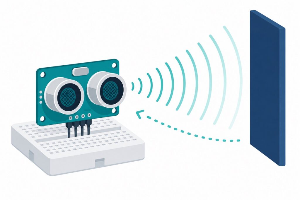
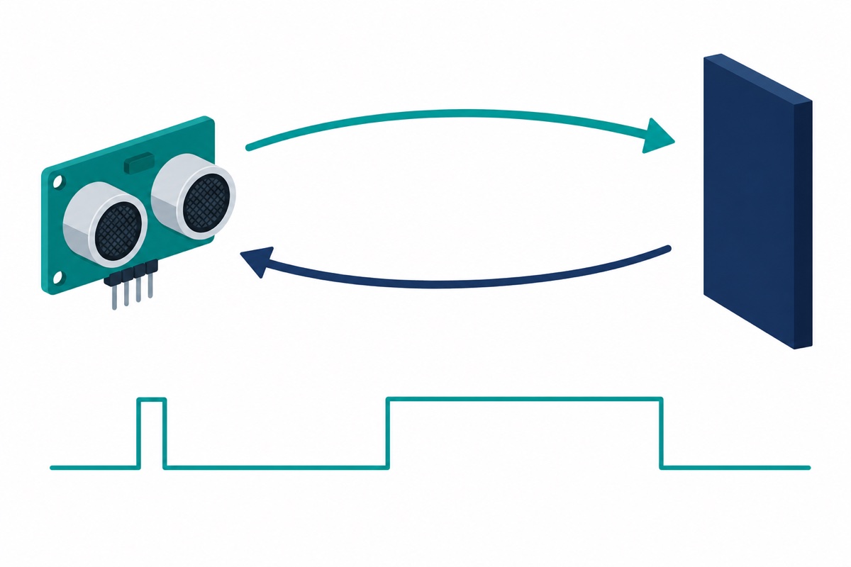
To use an HC-SR04 with an Arduino, power it from 5V, send a 10 µs HIGH pulse on TRIG, then time how long ECHO stays HIGH with pulseIn(). Distance in centimetres = that microsecond figure ÷ 58. The divide-by-two for the sound’s round trip is already baked into the 58, which is why the number looks arbitrary at first glance.
What do the HC-SR04’s four pins do?
The HC-SR04 presents four pins in a fixed order — VCC, TRIG, ECHO, GND — silkscreened next to the header — on the front of some batches, the back of others. VCC and GND are power; TRIG is an input you drive; ECHO is an output the module drives back at you.
The HC-SR04 is a 5V part: its datasheet gives a working voltage of DC 5V and a working current of 15 mA. That is a light load, easily supplied by an Uno’s own 5V rail — unlike the servos in our 180° vs 270° vs 360° servo guide. That 5V figure starts to matter the moment you leave the Uno, as the ESP32 section below explains.
Parts list
 Ultrasonic Sensor HC-SR04 Ultrasonic Range Detection Distance Finder Obstacle avoidance For Arduino Application
 Arduino Uno Compatible SMD UNO R3 with Type B Cable - ATMEGA328P with CH340G-Microcontroller Project
 MB102 Breadboard 170 400 830 Holes Breadboard Donut Board Arduino Prototype Multi Color - BREADBOARD (830 HOLES)
 40pcs Dupont Wire 10cm 20cm 30cm for Breadboard DIY Experiment Jumper Wire Breadboard wire - DUPONT WIRE M-F 20CM
How do I wire an HC-SR04 to an Arduino Uno?
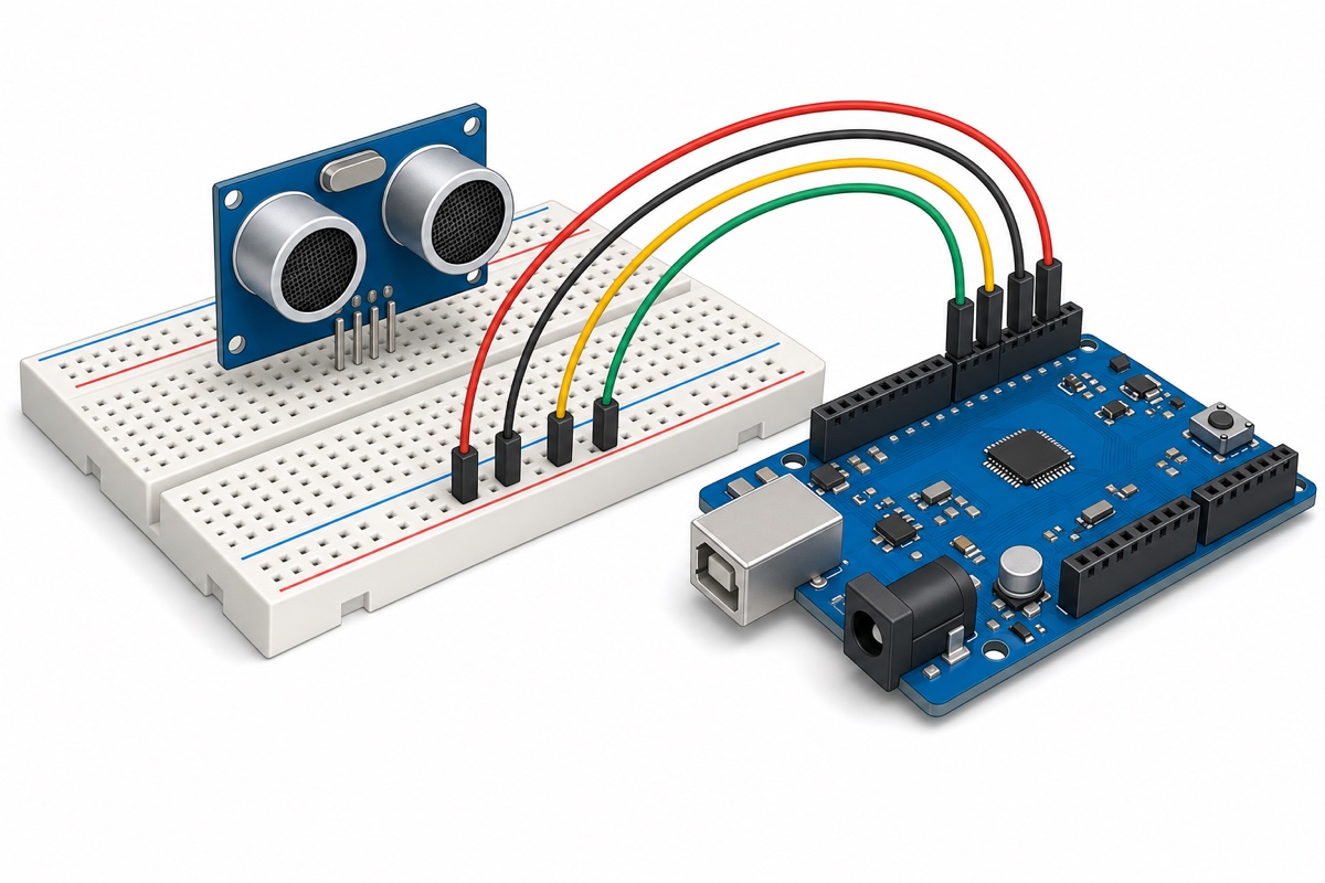
The HC-SR04 needs exactly four male-female jumper wires to reach an Uno. TRIG and ECHO can go to any two digital pins — 9 and 10 below are just a convention.
| HC-SR04 pin | Arduino Uno pin | Note |
|---|---|---|
| VCC | 5V | Must be 5V — the 3.3V pin will not reliably run a classic HC-SR04 |
| TRIG | D9 (any digital pin) | OUTPUT — you pulse this |
| ECHO | D10 (any digital pin) | INPUT — the module drives this HIGH |
| GND | GND | Shared ground is not optional |
Swapping TRIG and ECHO gives you zero readings until you swap back. It is usually survivable but not harmless in principle: your Arduino’s TRIG output ends up wired to the module’s ECHO output, and two outputs push against each other whenever they disagree.
What is the basic HC-SR04 Arduino code?
The HC-SR04 needs no library — three digitalWrite() calls plus one pulseIn() is the whole driver. Upload it, open Serial Monitor at 9600 baud, and wave your hand at the sensor.
// HC-SR04 basic distance reader - Arduino Uno
// TRIG on pin 9, ECHO on pin 10.

const int TRIG_PIN = 9;
const int ECHO_PIN = 10;

void setup() {
  Serial.begin(9600);
  pinMode(TRIG_PIN, OUTPUT);
  pinMode(ECHO_PIN, INPUT);
}

void loop() {
  // 1. Start from a clean LOW, then send the 10 us trigger pulse.
  digitalWrite(TRIG_PIN, LOW);
  delayMicroseconds(2);
  digitalWrite(TRIG_PIN, HIGH);
  delayMicroseconds(10);
  digitalWrite(TRIG_PIN, LOW);

  // 2. Measure how long ECHO stays HIGH, in microseconds.
  //    30000 us cap = give up past about 5 m of target distance
  //    (30000 / 58 = 517 cm; the sound itself covers ~10 m out and back).
  //    It also sits under the ~38 ms pulse the module emits when it sees nothing.
  long duration = pulseIn(ECHO_PIN, HIGH, 30000);

  // 3. Convert. 58 = round-trip microseconds per centimetre.
  if (duration == 0) {
    Serial.println("No echo - out of range, or nothing reflected back");
  } else {
    float distanceCm = duration / 58.0;
    Serial.print(distanceCm);
    Serial.println(" cm");
  }

  delay(100);   // datasheet asks for at least 60 ms between pings
}
Why divide by 2, and where does the 58 come from?
The HC-SR04’s ECHO pulse measures a round trip, and that single fact explains both constants. When TRIG gets its 10 µs pulse, the module fires eight cycles of 40 kHz ultrasound, then holds ECHO HIGH for exactly as long as the burst takes to reach your target and return.
Sound travels at roughly 343 m/s in room-temperature air, or about 0.0343 cm per microsecond. The pulse covers the distance twice, so distance = (time × 0.0343) ÷ 2 — that is time ÷ 58.3, which the datasheet rounds to ÷ 58. (The datasheet also prints 340 m/s beside that ÷ 58, which would give ÷ 58.8 — a small inconsistency of its own.) Many sketches instead write duration / 29.1 / 2, which is ÷ 58.2. All of these land within 1% of each other, and air temperature moves the speed of sound further than that.
Prefer to see the whole cycle on video? This walkthrough covers it end to end:
What is the HC-SR04’s real range, and what makes readings fail?
The HC-SR04 is specified for 2 cm to 400 cm, with ranging accuracy reaching 3 mm and an effectual measuring angle under 15°. That 15° cone is the spec beginners never account for.
| Spec | Value | What it means for your build |
|---|---|---|
| Range | 2 cm – 400 cm | Below 2 cm is a blind zone: the 8-cycle 40 kHz burst takes 200 µs to transmit, but a 2 cm round trip takes only about 116 µs, so the echo gets back before the module has finished sending |
| Accuracy | up to 3 mm | Best case: a flat hard target, square on |
| Measuring angle | under 15° | A cone, not a laser — it sees the nearest thing in the cone |
| Working voltage / current | 5V DC / 15 mA | Safe on an Uno’s 5V pin, unlike a servo |
| Burst frequency | 40 kHz, 8 cycles | Inaudible; nearby sensors cross-talk |
| Measurement cycle | 60 ms minimum | Ping sooner and the previous burst has not faded, so its lingering echo lands in the next measurement |
| Module size | 45 × 20 × 15 mm | Size the enclosure cut-out around both transducer cans |
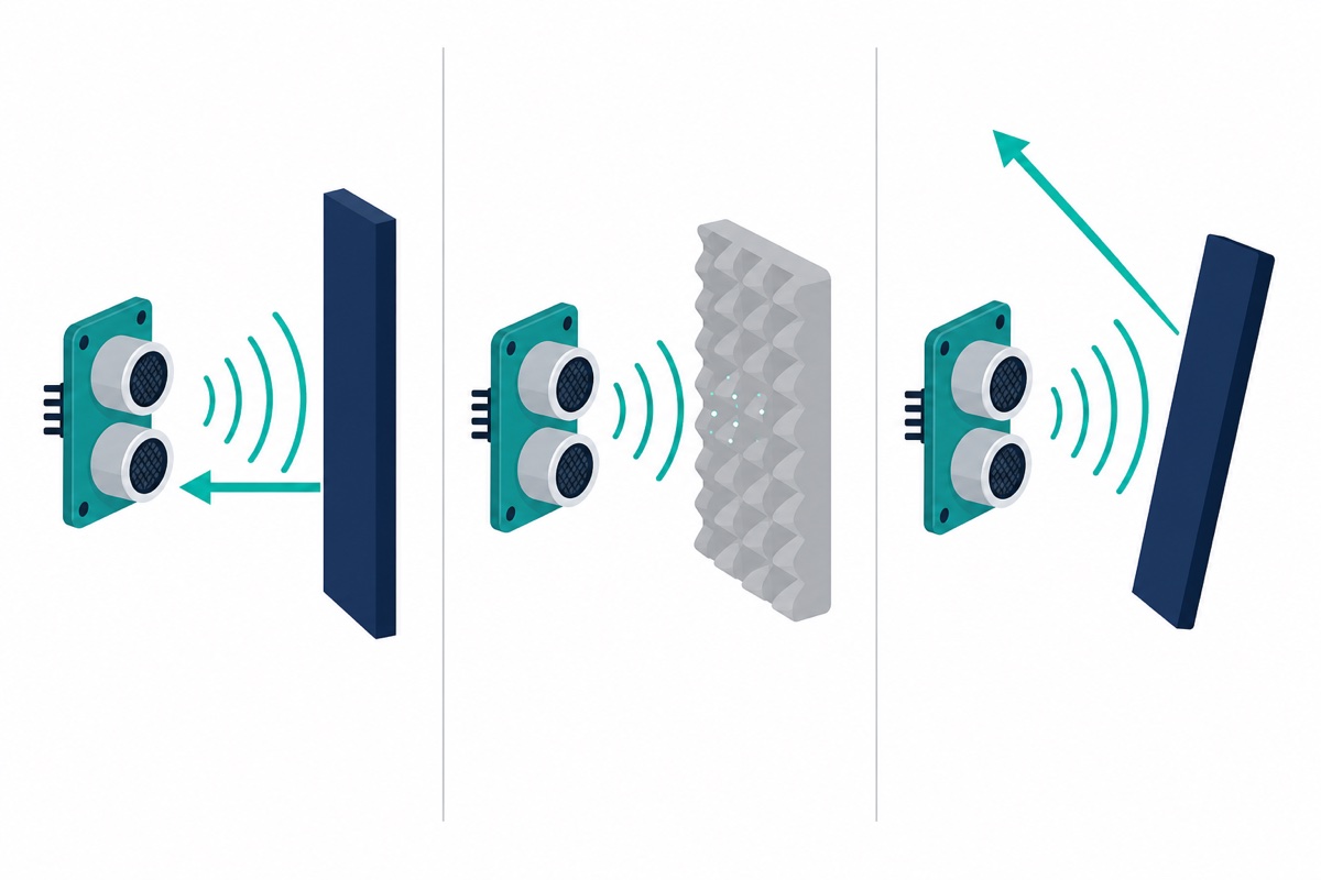
Four target types defeat the sensor regardless of your code. Soft or fibrous surfaces — cloth, foam, a stuffed toy — absorb the burst instead of reflecting it. Angled surfaces bounce it sideways like light off a mirror.
Objects smaller than the beam cone get missed entirely, and anything under 2 cm sits in the blind zone. Before you blame the sketch, check what you are pointing the sensor at.
How do I stop random 0 readings and jitter?
When the HC-SR04 finds nothing, it does not leave ECHO low — the datasheet says the pin gives a 38 ms high pulse instead. Read that with no timeout and you get about 38000 µs, which converts to a bogus 655 cm rather than an obvious error. The 30000 µs timeout in the sketch above sits just under that 38 ms, so a no-obstacle ping comes back as a clean 0. The one-second freeze people complain about is a different failure: when ECHO never rises at all — a loose wire, no shared ground, a dead module — pulseIn() blocks for its full one-second default. Either way, pass an explicit timeout.
For jitter, take several readings and use the middle one. A median rejects wild values far better than an average, because one bad reading cannot drag the result.
// Median of 5 readings - rejects the occasional wild value.
// Uses the TRIG_PIN / ECHO_PIN constants from the sketch above.

long readOnce() {
  digitalWrite(TRIG_PIN, LOW);
  delayMicroseconds(2);
  digitalWrite(TRIG_PIN, HIGH);
  delayMicroseconds(10);
  digitalWrite(TRIG_PIN, LOW);
  return pulseIn(ECHO_PIN, HIGH, 30000);
}

float readMedianCm() {
  long s[5];
  for (int i = 0; i < 5; i++) {
    s[i] = readOnce();
    delay(60);                 // respect the 60 ms measurement cycle
  }
  for (int i = 1; i < 5; i++) {          // insertion sort, 5 items
    long k = s[i];
    int j = i - 1;
    while (j >= 0 && s[j] > k) { s[j + 1] = s[j]; j--; }
    s[j + 1] = k;
  }
  if (s[2] == 0) return -1.0;  // middle reading timed out
  return s[2] / 58.0;
}
The NewPing library does all this for you: it sets a timeout automatically, avoids pulseIn() entirely, and ships a ping_median() helper. Plain pulseIn() is fine for learning and for one sensor; reach for NewPing when you run several sensors or cannot afford a blocking loop.
Can I use an HC-SR04 with an ESP32 or another 3.3V board?
A 3.3V trigger usually works — the datasheet calls TRIG a TTL input, and 3.3V clears a TTL threshold — though it is marginal on modules whose on-board microcontroller uses 5V CMOS input levels. ECHO is the real problem: it drives back a full 5V, and Espressif rates ESP32 GPIOs to 3.6V, telling you to add a voltage divider above that. Wire ECHO straight to an ESP32 and you are running the pin out of spec.
The fix is a two-resistor divider on ECHO only: 1 kΩ from ECHO to the GPIO, 2 kΩ from that same node to GND. That drops 5V to 5 × (2 ÷ 3) = 3.33V. TRIG connects directly, no divider needed. Alternatively, buy the HC-SR04P variant, which runs on 3V–5.5V; the classic HC-SR04 is a 5V part. ESP32 not showing up at all? That is a separate problem — see our guide on fixing an ESP32 that is not detected.
Common mistakes we see from real customers
The HC-SR04 draws more questions from school RBT and final-year-project builders than almost any other sensor we sell, and the same handful of failures come back week after week. None of them are sensor defects.
The most common one is a module whose pin labels are faded, missing or barely legible — the tiny silkscreen beside the header does not survive much handling. The order is always VCC, TRIG, ECHO, GND, so read the pins off the table above instead of guessing, and rule that out before deciding the module is faulty.
Another regular is readings that come out exactly double. That is the missing ÷2 — divide by 58, not 29. Close behind is a sketch that seems to hang or stutter, which is almost always pulseIn() called with no timeout argument, blocking for its full one-second default whenever ECHO never rises at all — a loose wire, a missing shared ground or a dead module.
Then there is the 15° cone. Builders aim at a target and forget that a table edge, a wall or their own enclosure sits inside the beam, so the sensor faithfully reports that nearer object instead. Mount the module looking into clear air.
Finally, ground. A sensor fed from one supply and signalling into an Arduino with no shared GND produces readings that look like pure noise — tie the grounds together. Our LM2596 buck converter guide covers building a clean 5V rail.
FAQ
How far can an HC-SR04 measure?
2 cm to 400 cm, with accuracy reaching about 3 mm in good conditions. Under 2 cm is a blind zone — the reading stops tracking and sticks near the module’s floor — and beyond roughly 4 m the echo is too weak to detect.
Why does my HC-SR04 always read 0 or the same number?
A constant 0 means pulseIn() timed out — usually TRIG and ECHO swapped, no shared GND, or the target absorbs sound. A value stuck near 655 cm is the module’s documented “no obstacle” output, a 38 ms ECHO pulse, so it is seeing nothing at all. A value that never changes can also mean you are pinging faster than the 60 ms measurement cycle allows, so each read still catches the previous burst’s echo.
Do I need a library to use the HC-SR04?
No. Three digitalWrite() calls plus one pulseIn() is the entire driver. NewPing is worth adding when you run several sensors or need non-blocking timing, but it is optional.
Can I connect an HC-SR04 directly to an ESP32?
TRIG yes, ECHO no. ECHO outputs 5V and ESP32 GPIOs are not 5V tolerant, so put a 1 kΩ / 2 kΩ divider on ECHO, or use the 3V–5.5V HC-SR04P variant instead.
Why is my measured distance exactly double the real one?
You divided by 29 instead of 58. The ECHO pulse covers the sound’s full out-and-back journey, so the round trip has to be halved — divide the microseconds by 58 to get centimetres.
Last updated July 2026. Stuck? Chat with us on WhatsApp.
