

Tutorials
Mini Aquaponics System for a School Project (RBT)
Sep
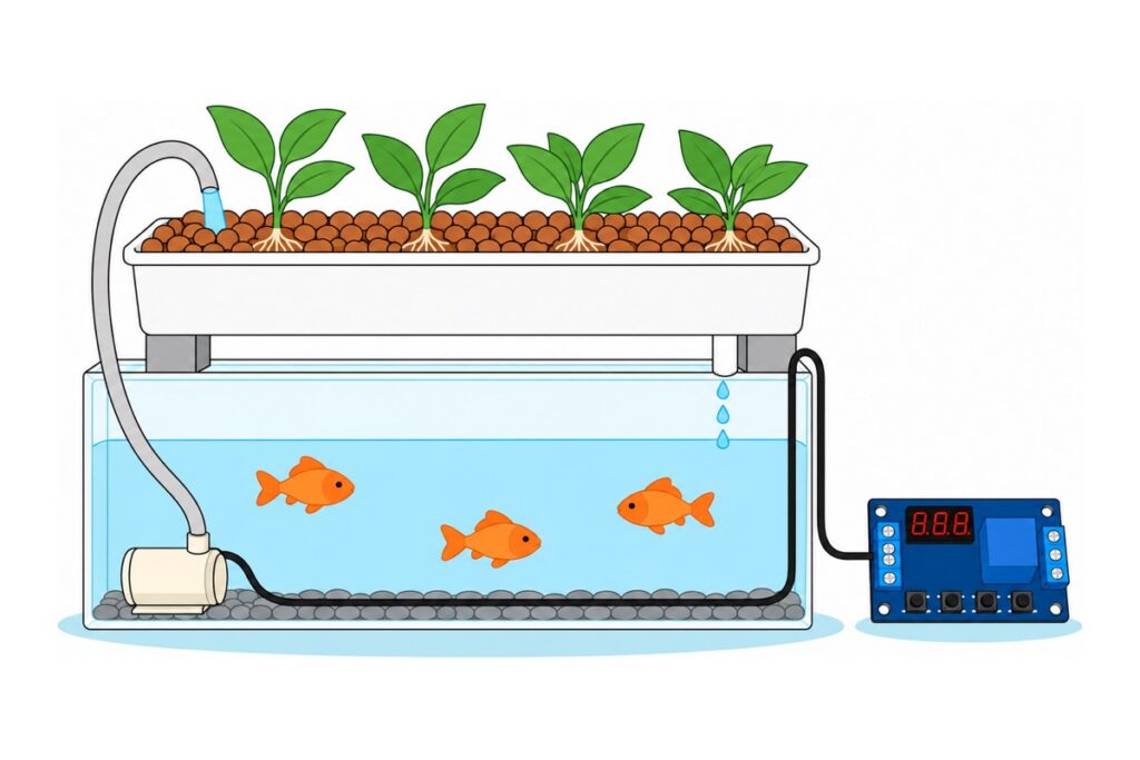
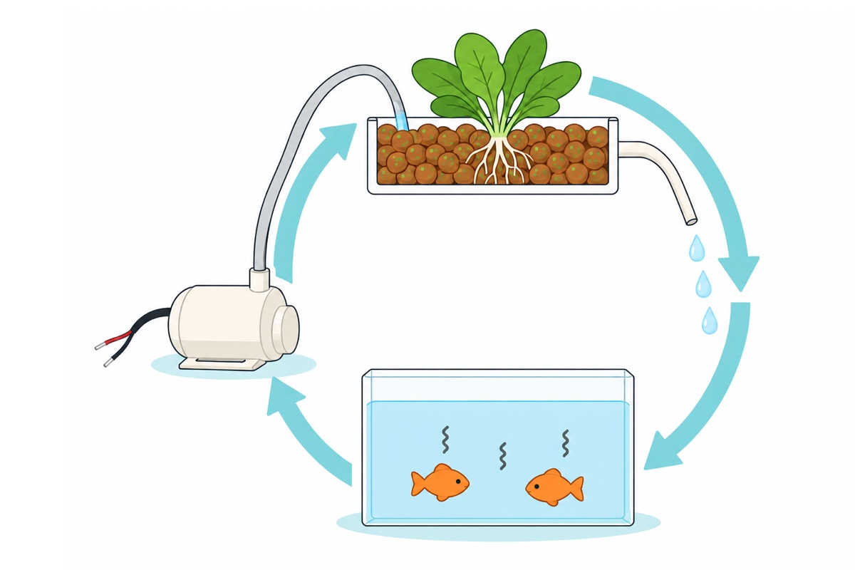
A mini aquaponics system for an RBT assignment is a fish tank at the bottom, a grow bed on top, and one 5V submersible pump that lifts the fish water into the bed on a timer cycle. The fish supply the nutrients, the media in the bed filters, and the water falls back into the tank by gravity. That pump has to run day and night.
What is aquaponics, and why is the pump the heart of the system?
Aquaponics is a closed water loop between fish and plants. Fish give off ammonia through their waste and their gills, and that ammonia is poisonous to the fish themselves. In the grow bed, the surface of the media (clay pebbles or gravel) becomes home to nitrifying bacteria that turn ammonia into nitrite, then nitrite into nitrate. Plant roots take up that nitrate as fertiliser, and the water — now stripped of its ammonia — falls back into the tank.
Three things in that loop are not allowed to stop. Nitrifying bacteria live as a film on the media and they are aerobic — their oxygen comes from the water flowing past them. Plant roots need water and air in alternation. And fish do not stop producing ammonia at night. That is why the 5V submersible pump is the one component that cannot be allowed to fail: stop the pump and the loop breaks in three places at once.
Electrical parts for a mini aquaponics system — all 5V, no soldering
 Mini Water Pump Submersible DC 3V-5V - 5V WATER PUMP
 Multi Function Relay Module Time Delay Timer Switch Control Board DC 12V 24V AC 110V 220V Programmable Automation
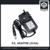 Power Supply Adapter DC Universal AC to DC Converter PSU 5V2A 5V3A 9V2A 12V2A - P.S. ADAPTOR (5V3A)
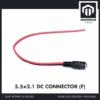 5.5x2.1mm DC Power Male Connector Plug Jack Adapter for Arduino DIY Electronics Projects - 5.5x2.1 DC CONNECTOR (F)
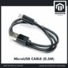 Data Cable Type-A Type-C MicroUSB Type-B 0.5m 1m 30cm 0.3m 100cm Data Transfer Upload Code - MicroUSB CABLE (0.5M)
Parts list
 Arduino Uno Compatible SMD UNO R3 with Type B Cable - ATMEGA328P with CH340G-Microcontroller Project
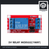 Relay Module 3.3V 5V 12V 1/2/4/8 Ways Optocoupler Trigger Relay Module 1 2 4 8 Channel Relay Module - 5V RELAY MODULE(1WAY)
 40pcs Dupont Wire 10cm 20cm 30cm for Breadboard DIY Experiment Jumper Wire Breadboard wire - DUPONT WIRE M-M 20CM
For the 'Arduino aquaponics' version if your teacher asks for programming: an Uno board, a one-channel relay module, and male-to-male dupont wires to land in that relay module's screw block.
The rest is not electronics, and you can get all of it from an aquarium shop or a hardware shop: clear hose of roughly 7 mm for the pump spout, two food containers (one for the bottom tank, one for the bed on top), LECA clay pebbles or gravel as the media, a USB charger head or a power bank, and electrical tape.
If what you need right now is the written part rather than the build, jump straight to the sample project report skeleton at the end of this guide — objective, design, materials, procedure, results and reflection, with sample content for this aquaponics project.
How should the two-tier layout be set up?
The grow bed has to sit higher than the tank’s water level so the water returns on its own without a second pump. How high can this pump actually push? Its electrical power is about 5 V × 0.15 A = 0.75 W. To lift water, the hydraulic power required is ρ·g·Q·H — at the pump’s flow rate (70–110 L/hr, roughly 2.5 × 10⁻⁵ m³/s) that comes to about 0.245 W for every metre of height. A magnetic-impeller pump this small converts less than 10% of its electrical power into water power, so your real budget is only around 0.05–0.07 W. That is why the flow collapses so fast for every centimetre you raise it: at 30 cm you still get about a litre a minute, but by one metre the flow is nearly gone.
In practice: put the lip of the bed around 30 cm above the tank’s water level. Then confirm it with a bottle test — run the pump at your project’s real height, aim the hose into a 1-litre bottle, and count the seconds until it fills. That gives you your real flow, not the catalogue flow.
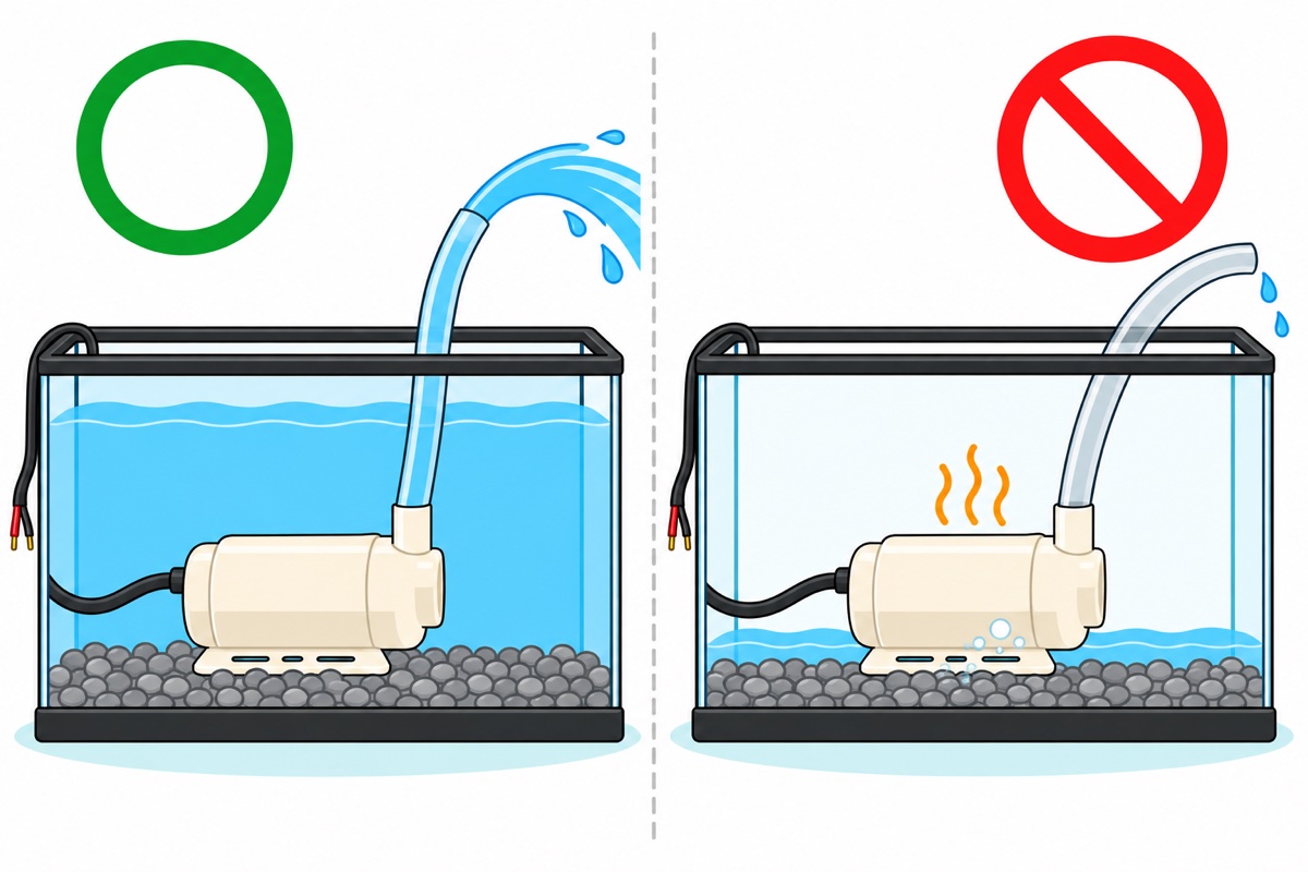
The tank has to be bigger than you think, and the reason is pure arithmetic: 2 to 4 litres of water moves up into the bed every time the pump runs, so the tank level drops by that much throughout the flood phase. Pick a container that still submerges the pump completely at that lowest level — allow at least twice the flood volume as reserve water above the pump’s head. A tank that is too shallow is the real cause of most burnt-out pumps in school projects: not because the student forgot to top up the water, but because the system itself pulls the water level below the pump’s spout every time it cycles.
A school bed does not need a bell siphon. Drill one small hole in the bottom corner of the bed and connect a short tube back to the tank. That hole drains all the time, but slower than the pump fills — so while the pump runs the bed rises, and while the pump is off the bed empties itself. That is the flood-and-drain cycle.
The size of that hole decides whether the cycle works at all, and it is the one number in this project that appears in no specification anywhere. It has to be small enough that the drain rate is far slower than the pump rate — otherwise the bed never rises — but big enough to empty the bed within the pump’s off time. Start with a 4 mm drill bit, then test it without the pump: pour 2 litres of water into the bed with the media already in it, and time how long it takes to stop dripping. Five to fifteen minutes is right. Done in a minute or two means the hole is too big, so plug half of it with a piece of rubber or switch to a finer tube; still wet after twenty-five minutes means open it up slightly. Lay a piece of mosquito netting or loose-weave cloth over the hole before the media goes in, because one LECA pebble sitting right on top of the hole is enough to choke it.
For a bed this small, fast-growing leafy greens — kangkung, spinach or lettuce — are the safest choice, because they are ready to harvest within one school term and their roots are shallow, which suits the flood-and-drain cycle. Sow seeds straight into damp LECA. If you are moving a seedling out of a pot, rinse every trace of soil off its roots first: soil carried in washes down into the tank and collects in the pump’s intake basket, and that is the cause of the flow that slowly disappears after two or three weeks with nothing visibly broken.
Watching someone lay out the tank, bed and hose helps before you cut up containers of your own:
https://www.youtube.com/watch?v=7ddmnSpTWzw
How often should the pump switch on and off?
The timer settings come from your bed’s volume, not from a guess. A school bed the size of a 5–10 litre container filled with LECA only holds about 40% water by volume, because the rest is stone — so 2–4 litres of water is all it takes to flood it. The pump gives 70–110 L/hr, which is 1.2–1.8 litres a minute at zero height; at 30 cm and through a hose, estimate about 1 litre a minute. 2–4 litres divided by 1 litre a minute gives 3 minutes as the starting on-time.
The off-time is decided by the roots. A bed that stays flooded turns anaerobic and the roots rot; a bed that stays dry kills the bacterial film on the media. Between those two failures, 30 minutes is a safe starting point in Malaysian weather — long enough for the bed to drain out and the roots to breathe, short enough that the media never has time to dry.
| Timer parameter | Starting value | Why |
|---|---|---|
| OP (on-time) | 3 minutes | Bed water volume (2–4 L) divided by real flow (~1 L/min) |
| CL (off-time) | 30 minutes | Enough to drain out and let roots breathe, not long enough to dry |
| LOP (cycle count) | --- |
No limit — the system must not stop after a set count |
Watch one full cycle before you leave the system alone. What you want is the water level stopping about 2 cm below the surface of the pebbles — that dry top layer is what keeps algae and mosquitoes out. If water spills out of the bed, cut OP by half a minute; if the level stops well short of the target, add half a minute.

How do you wire the timer relay module so the pump cycles by itself?
The multi-function relay timer module carries two blue screw blocks: four ways on the left edge for power and trigger, three ways on the right edge for the relay contacts (NO, COM, NC). The board can be powered from 6–30V DC through the screw terminals or from 5V through the micro-USB port on its top edge. We use the micro-USB port — do not feed 5V into the screw terminals. The reason is visible on the board itself: the screw-terminal input passes through a 78M05 voltage regulator, and a linear regulator of that type has to be given one to two volts more than the 5V it puts out. Give it exactly 5V and its output sags to around 4V — the display may still light up, but the relay coil is not strong enough to pull the contacts in, so the pump switches on and off erratically. The micro-USB port feeds the 5V rail directly and bypasses that regulator, so 5V stays 5V. That is why the screw-terminal range starts at 6 V.
The pump does not share a supply with the board. It gets its own 5V rail from the 5V 3A adapter, and the relay only makes and breaks the positive wire of that rail. These two separate supplies do not clash because a relay contact is a mechanical contact — moving metal, fully isolated from the board’s circuitry. The pump draws only 100–220 mA, so that 3A adapter is deliberately oversized and never gets warm.
| Connection | From | To | Note |
|---|---|---|---|
| Timer board power | USB charger head or power bank, through a micro-USB cable | Micro-USB port on the timer module | 5V. The 6–30V screw terminals stay empty |
| Pump rail (+) | Red wire on the 5.5×2.1 mm female jack, plugged into the adapter | COM terminal on the three-way block | This jack is the pigtail type — the red and black wires are already fitted |
| Pump switch | NO terminal on the three-way block | Pump’s red wire | NO is open when the relay coil is unpowered, so losing power means the pump stops |
| Pump return path | Pump’s black wire | Black wire of the female jack | Twist them together and wrap in electrical tape, and put that joint outside the tank, higher than the water level |
| NC | — | — | Not used at all |
For the timer settings, the mode you want is P3.2: once power comes up, the relay stays on for OP and off for CL over and over without needing any trigger signal (XY-J02 manual). Mode P3.1 looks the same but waits for a trigger signal first — that is the usual reason a board “does not work” even though it is wired correctly. And this board leaves the factory in default mode P1.1, so the mode really does have to be changed by hand.
Hold SET for two seconds to enter mode selection, pick P3.2 with UP/DOWN, then press SET to step through OP, CL and LOP. While each value is blinking, the STOP button moves the decimal point — and it is that point, not the number, that sets the unit: one point on the last digit means seconds (1–999 s), while every decimal point lit means minutes (1–999 min), and that is what you need for OP 3 and CL 30. Once all three values are set, hold SET for two seconds again to save and exit; the saved mode blinks before the display returns to the main screen — a board left sitting inside the settings screen will not cycle at all.
Two signs confirm the board is right before you walk away from it. On the main screen — not the settings screen you were just in — the display shows a decimal point while the relay is on and no point at all while it is off, so you can read the current phase at a glance. And every time power comes up, the board blinks its current mode before going to the main screen: unplug the micro-USB cable and plug it back in once, and if it blinks P3.2, your system will restart itself every time mains power returns after an outage, with nobody having to touch it. Every mode is explained in full in our timer relay module guide, and adapter and barrel jack selection in the DC power supply guide.
Adapter or battery, and why must the pump run at night?
Ammonia does not stop at night, because the fish do not stop breathing. If the pump is off from 10 pm to 7 am, ammonia builds up in the tank for nine hours while the bacterial film on the media loses its supply of water and oxygen. The next morning you get cloudy water, a foul smell, and roots that have already dried — and that happens a few days before presentation day, not on the day itself.
The arithmetic explains why the adapter wins. The timer board draws roughly 20–50 mA continuously, say 30 mA at 5 V = 0.15 W. The pump draws 0.75 W but only for 3 minutes in every 33 — that is 9% of the time — so it averages just 0.07 W. Total, about 0.22 W. A 2200 mAh 18650 cell stores 3.7 V × 2.2 Ah ≈ 8.1 Wh, and a boost module to 5V returns about 85% of that, or 6.9 Wh. Divide: about 31 hours. This system has to run for weeks, so a battery means recharging every single day for that whole stretch — and the day you forget is the day the bed dries out. Notice too which part eats the power in that calculation: the timer board, not the pump. A wall adapter removes the problem completely, and the whole system uses less than one kilowatt-hour a month.
Safety: the adapter is the only part that touches mains power. Never open it, cut into its body, or splice its wires. Keep the adapter and the wall socket far higher than the water level, and put a drip loop in the cable so water running along the cable drips onto the floor before it reaches the plug. The timer board is an open PCB with no cover: put it higher than the tank’s rim, or in a plastic box with the cables leaving from underneath. Splashes and drops of condensation falling onto it will wreck that circuit long before it becomes a danger to you, and a dead board means a pump that never comes back on. Everything on the pump side is only 5V DC, so it is safe to handle.
What if the teacher asks for an Arduino version?
If the assignment calls for programming, an Arduino Uno replaces the timer board and drives a red one-channel relay module. That module’s input side is a DC+/DC−/IN screw block, so male-to-male dupont wires are the right type: the pin on one end is clamped under the screw, the other end goes into the Uno’s female headers. The sketch below uses millis() rather than delay(), so the board stays free to read sensors later.
// Aquaponics pump cycle - Arduino Uno + 1-channel relay module.
// Pump ON 3 minutes, OFF 30 minutes, repeating forever.
// No long delay(), so the board stays free to do other work.
//
// Wiring (same as the table in the article):
//   Uno 5V  -> DC+   on the relay module's screw block
//   Uno GND -> DC-
//   Uno D7  -> IN
//   5V adapter (+) -> COM        NO -> pump's red wire
//   Pump's black wire -> adapter (-)

const uint8_t PIN_RELAY    = 7;
const bool    AKTIF_RENDAH = true;   // H/L jumper on L. Set to false if the relay is inverted.

const unsigned long MASA_HIDUP = 3UL  * 60UL * 1000UL;   // 3 minutes  = 180000 ms
const unsigned long MASA_MATI  = 30UL * 60UL * 1000UL;   // 30 minutes = 1800000 ms

bool          pamHidup  = false;
unsigned long tandaMasa = 0;

void tetapkanPam(bool hidup) {
  pamHidup = hidup;
  // On a low-trigger module, LOW is what energises the relay.
  digitalWrite(PIN_RELAY, (hidup == AKTIF_RENDAH) ? LOW : HIGH);
  Serial.println(hidup ? F("Pump ON") : F("Pump OFF"));
}

void setup() {
  Serial.begin(9600);
  // Set the level first, then make it an OUTPUT - avoids a short pulse at boot.
  digitalWrite(PIN_RELAY, AKTIF_RENDAH ? HIGH : LOW);
  pinMode(PIN_RELAY, OUTPUT);

  tandaMasa = millis();
  tetapkanPam(true);   // start with one flood so the bed is wet from the beginning
}

void loop() {
  unsigned long sekarang = millis();
  unsigned long hadMasa  = pamHidup ? MASA_HIDUP : MASA_MATI;

  // Unsigned subtraction - safe even when millis() rolls over after ~49 days.
  if (sekarang - tandaMasa >= hadMasa) {
    tandaMasa += hadMasa;
    tetapkanPam(!pamHidup);
  }
}
Sample RBT aquaponics project report skeleton: six sections
Fill in the table below as you build, not the night before you hand it in — numbers like the bottle-test flow and the OP/CL settings only exist if you record them while they happen.
| Section | What the teacher is looking for | Content for this project |
|---|---|---|
| Objective | One measurable sentence, not a general aspiration | Build a mini aquaponics system that circulates water automatically and grows leafy greens with no added fertiliser for four weeks |
| Design | A labelled sketch + the reason behind every decision | Two-tier layout; bed 30 cm above the water level; gravity drainage through a single hole; flood-and-drain cycle |
| Materials and tools | A complete list with quantities and specifications | The parts list above (pump voltage, current and flow recorded), plus containers, media, hose and tape |
| Procedure | Numbered steps someone else can repeat | Rinse the media, assemble the bed, drill the drain hole, wire the relay to the table, set mode P3.2, test one cycle, cycle the system on water alone before the fish go in |
| Results | Measured data, not opinions | Bottle-test flow (L/min), real flood time, weekly plant height, notes on water clarity |
| Reflection | Problems that came up and what you changed | Example: the original 5-minute OP caused an overflow, cut to 3 minutes after watching the first cycle |
Reflection is the cheapest section to fill in and the most convincing to a teacher, because it is the only one that proves the system was actually run — so record every failure and its fix. Other RBT automation projects, such as the automatic dustbin, use the same report skeleton.
Common mistakes that sink the project on presentation day
Running the pump dry. This pump is cooled and lubricated by the water passing through it. Switch it on out of the water even for a few seconds “just to test”, and its bearing and impeller spin dry and heat up straight away. Submerge the pump completely first, every single time — which is also why a nearly empty tank destroys the pump.
The water level dropping unnoticed. An open system loses water through evaporation and through the leaves, and a full bed holds several litres throughout the flood phase. Mark a minimum line on the tank wall and top it up every few days. To make that automatic, a water level controller with a relay adds a sensor-controlled top-up pump.
A blocked hose. New media carries clay dust, and that dust collects in the pump’s 7 mm spout until the flow has halved with nothing visibly broken. Rinse the media until the runoff is clear before it goes into the bed, and check the pump’s basket filter every week.
Leaving the timer units in seconds. The decimal point on the display sets the unit, so “030” can mean 30 seconds or 30 minutes: all three decimal points lit means minutes, one point at the end means seconds. A pump that runs 3 minutes in every 30 seconds is running essentially non-stop, the bed overflows, and the floor gets wet. Press STOP while that value is blinking to change the unit, then confirm it against a clock before you leave the system alone.
Fish going in on day one. Colonisation by nitrifying bacteria is a slow process — the FAO allows three to five weeks to cycle a new system. Run the system on water alone first, because on day one the ammonia has nothing there to convert it. To shorten that period, take a handful of media or a filter sponge from an aquarium that has been running a long time and mix it into your bed as a bacterial seed. Plan your project schedule around this figure, not the other way round.
FAQ
What is aquaponics, briefly, for an RBT project?
Aquaponics is a closed water loop between fish and plants. The fish give off ammonia, nitrifying bacteria living on the media surface in the grow bed convert it into nitrate, plant roots take up that nitrate as fertiliser, and the filtered water flows back into the fish tank by gravity.
What has to be in a Form 2 RBT aquaponics project report?
Six sections: objective (one measurable sentence), design (a labelled sketch and the reason behind every decision), materials and tools (a complete list with quantities and specifications), procedure (numbered steps someone else can repeat), results (measured data such as pump flow rate, real flood time and weekly plant height), and reflection (problems that came up and what you changed). The full skeleton with sample content is in the report table above.
How often should a mini aquaponics pump run?
Start with 3 minutes on and 30 minutes off, repeating with no limit. The on-time comes from the bed volume: a 5–10 litre container filled with LECA needs 2–4 litres of water, and the pump gives about 1 litre a minute at real height. The off-time is long enough for the bed to drain out so the roots can breathe, but not long enough to dry.
Can the aquaponics pump be switched off at night to save electricity?
No. Fish give off ammonia all night long, and the bacteria that convert it are aerobic — they get their oxygen from the flowing water. Stop the flow for nine hours and ammonia builds up while the bacterial film and the roots dry out. The whole system uses less than one kilowatt-hour a month anyway.
Do you need an Arduino for a school aquaponics project?
Not necessarily. A multi-function relay timer module in mode P3.2 switches the pump on and off on a cycle without a single line of code. Use an Arduino Uno with a one-channel relay module only if the assignment specifically calls for programming, or if you plan to add sensors later.
Why does my 5V water pump hum but no water comes up?
Three common causes, in the order to check them. The 7 mm spout or the intake basket is blocked with media dust; the water level has dropped until the pump is sucking air; or the bed is too high — this pump’s flow falls away quickly past half a metre and is almost gone by one metre.
Last updated September 2026. Stuck? Chat with us on WhatsApp.
