

Tutorials
Water Level Sensor for a Water Tank: Automatic Pump Control
Aug
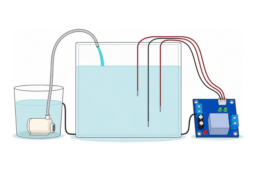
A water level relay controller fills a tank by itself with no microcontroller and no code. Two conductive probes hang at two heights, and the module’s relay closes to run the pump when the water drops past the lower tip, then opens when the water reaches the upper tip. The gap between those two tips is the whole trick.
Before the controller: does the pump itself run?
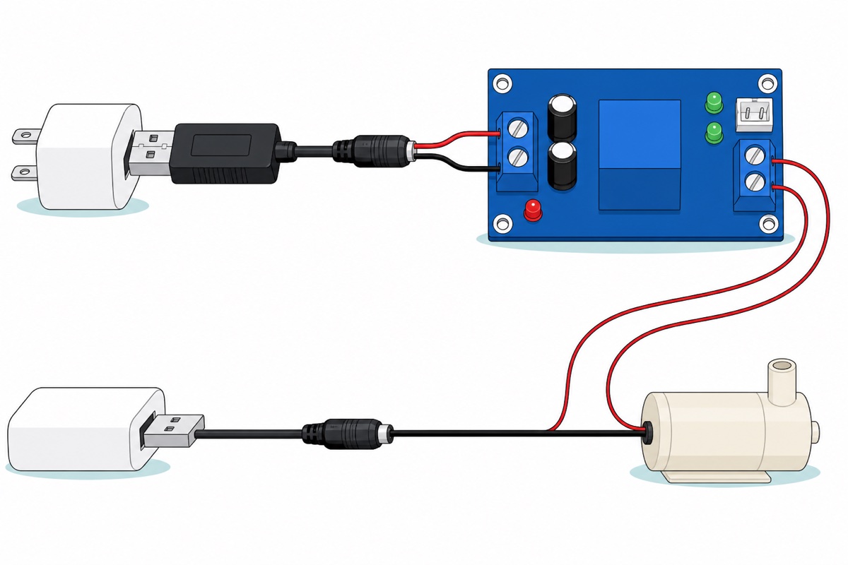
A customer wrote to us with a brand-new pump in hand: “do you know how to actually connect the water pump after i buy it to test if its actually working or not”. The pump needs nothing from the controller. Plug a USB-to-5V-jack cable into any phone charger, push its barrel plug into a female barrel socket pigtail, twist that socket’s red lead to the pump’s red and black to black, and water should move at once.
Put the pump in the water before powering it: it is cooled and lubricated by the liquid it moves, so a dry run heats the impeller and bearing for nothing. And it is a water pump — another customer asked in Malay, “yg ni blh buat oxsigen angin ka.. atau untk pump air ja” (air or oxygen, or only water?). Only water: an impeller moves almost no mass in air, and the controller senses conductivity through liquid.
Parts list — automatic tank top-up, no code
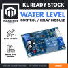 Water Level Relay Controller Liquid Level Detection Auto Water Sensor Tank Pump Control Switch
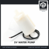 Mini Water Pump Submersible DC 3V-5V - 5V WATER PUMP
 USB To 9V DC Jack Cable 5.5 x 2.1 mm 5V 9V DC Power USB Cable Connector Jack - USB TO 12V DC JACK
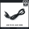 USB To 9V DC Jack Cable 5.5 x 2.1 mm 5V 9V DC Power USB Cable Connector Jack - USB TO 5V DC JACK
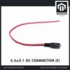 5.5x2.1mm DC Power Male Connector Plug Jack Adapter for Arduino DIY Electronics Projects - 5.5x2.1 DC CONNECTOR (F)
Optional extras
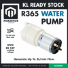 R365 12 Water Pump Pnuematic Diaphragm Water Pump Watering System Motor
 Electrical Insulation Tape 18mm x 10m PVC Color Coded Marking Red White Blue Yellow Green Black - ELECTRICAL TAPE (RED)
The R365/R385 diaphragm pump is the self-priming upgrade that sits outside the tank on two hose barbs instead of in it. It arrives as a bare motor with two gold solder tabs and no leads, so you will solder to it, and at 12 V and 0.5–0.7 A it needs its own 12 V supply rated for a full amp — the USB boost cable in the main list cannot feed it. The insulation tape covers the one twist joint in this build and holds the probe wires at height against the tank wall.
Two separate USB outputs are needed — a charger and a power bank will do — and so are two vessels, which is the part nobody mentions. The pump has to stay under water, so it cannot live in the tank it is filling. It sits in the source — a bucket, a drum, a sump fed from elsewhere — and pushes water up a tube into the tank, while the probes hang in the tank at the far end. Nothing in this build watches the source, so keeping the pump covered stays your job.
Why does the XHM203W need two probes instead of one?
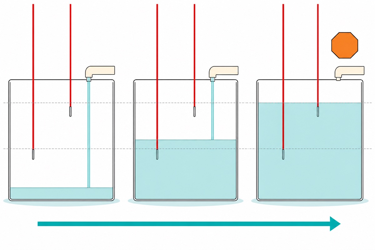
The XHM203W uses two because one cannot answer the question. A single tip gives two states, wet and dry, changing over at one exact height — and water is never still. Ripple from the pump itself, or a cup drawn off the tank, crosses that height repeatedly, and the pump would start and stop several times a second, wearing out relay contacts and motor brushes alike. Two tips give a band instead: the lower one sets where filling restarts, the upper one where it stops.
| Water level | Lower tip | Upper tip | Pump |
|---|---|---|---|
| Below the lower tip | Dry | Dry | Starts, and runs |
| Rising through the band | Wet | Dry | Keeps running |
| At or above the upper tip | Wet | Wet | Stops |
| Falling back through the band | Wet | Dry | Stays off |
Look at rows two and four. The probes report the identical thing — lower wet, upper dry — and the correct answer is opposite in each. Nothing read at that instant can tell them apart, so the board has to remember. That memory is a set–reset latch, the job of the small signal parts wired between the probe sockets and the relay coil: the lower tip going dry sets it, the upper tip going wet resets it, and in between it holds its last answer. Every level controller worth buying works this way; the band is called hysteresis.
What do the Chinese markings on the board mean?
Three of the XHM203W’s four connections are labelled in Chinese, and the fourth is not labelled at all. All four:
| Marking | What it is | What goes there |
|---|---|---|
| Left blue screw terminal | Power in, 12 V AC or DC | The 12 V USB boost cable, via a female barrel socket pigtail |
| 下水位 (white 2-pin socket) | Lower level — the restart height | One probe cable, plugged in |
| 上水位 (white 2-pin socket) | Upper level — the shut-off height | The other probe cable, plugged in |
| 输出 (right blue screw terminal) | Output — the relay’s bare switch contacts | One leg of the pump’s own supply, cut and landed on the two screws |
Power polarity is forgiving, and the board shows you why: the black block behind the input terminal is a bridge rectifier, which hands the regulator the same polarity whichever way the supply arrives — also why the module takes 12 V AC as happily as DC. There is no + or − printed on that terminal, and with the bridge in circuit there does not need to be. Both probe cables come in the box: a white two-pin plug on a red and a black wire whose bare tinned ends are the electrodes.
Prove the board dry before you trust it with a tank. Power it on its own with nothing on the 输出 screws — the red LED lights. Then dip one cable’s two bare tips into a mug of tap water and lift them out again, and repeat with the other cable, watching the two green indicators beside the sockets and listening for the relay. The board should react as water arrives and leaves, with one click as it decides to run the pump and another as it decides to stop. A mug is a much better place than a tank to find out that something is wrong.
Dean Satchell demonstrates this exact board variant:
Why does the pump get its own power supply?
The 输出 terminal supplies nothing. It is two screws wired straight to the relay’s contacts — a switch with no voltage of its own, which is what a dry contact means. The relay is a SONGLE SRD-12VDC-SL-A, and that -A is Songle’s ordering suffix for a single Form A contact: normally open, with no normally-closed position at all. Hence two screws, not the NO/COM/NC three on a plain relay module or a timer relay — there is only one contact to bring out.
So the pump brings its own supply and you cut one of its two leads — either one on a low-voltage DC pump, though cutting the red leaves the black as one unbroken run — and land the two cut ends on the 输出 screws, taping the black lead’s own twist joint back to the barrel socket while you are there. The arithmetic is why our build gives it a whole second USB lane. The module draws about 20 mA of logic; the relay coil is 400 Ω at 12 V, so 12 ÷ 400 = 30 mA more when it pulls in. Fifty milliamps is a tenth of the 12 V boost cable’s 500 mA recommended load — comfortable, until a pump joins it.
Add the optional 12 V diaphragm pump at 0.5–0.7 A and the total hits 0.75 A, the cable’s absolute maximum with nothing spare — and delivering that 8.4 W (12 V × 0.7 A) at a realistic 85 % conversion would pull nearly 2 A from the USB port, exactly the cable’s stated input ceiling. So the 5 V pump at 0.1–0.2 A gets its own plain 5 V cable and its own barrel socket.
The relay is rated 10 A at 250 V AC, so a mains pump is within the contact’s ability — but the wiring, enclosure and earthing on that side are not a hobby step, and our relay module safety guide draws that line.
Where exactly do the probe tips go?
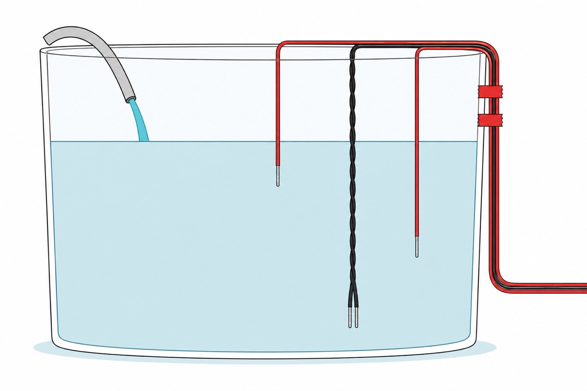
In the liquid, hanging free, clear of the tank wall. The XHM203W pushes a tiny current between two bare tips and watches whether the water completes the circuit, so the water itself is the switch. Tape a tip flat to the wall and you get two failures: it may not be truly immersed when the level says it is, and a film of condensation or algae down the wall can bridge it when the tank is empty.
The two cables give four bare tips, and only two of them set heights. The black wire of each pair is the shared reference: twist those two together into one strand and hang it near the bottom, deeper than either red tip, so it is under water whenever there is water to read. Hanging each black tip deep on its own works just as well — twisting only saves you a second wire to manage. The red tip from 下水位 then hangs where filling should restart, and the red tip from 上水位 where it should stop. Set them well apart — a hand’s width in a bucket-sized tank — because that gap is the hysteresis. Tape the wires to the wall above the waterline with insulation tape so the tips cannot drift; our guide on insulation tape versus heat shrink covers extending a run.
The method needs dissolved minerals to carry that current. Tap water, rainwater and pond water all work; distilled or deionised water does not, because pure water is an excellent insulator — the dissolved salts conduct, not the H₂O. Oils and fuels carry no ions at all.
What happens if a probe stops reporting?
Every way a probe can fail looks identical to the XHM203W: a tip lifted clear of the water, a plug tugged out of its socket, a black reference left dangling, a tinned tip gone dull under a film of scale. All of them mean no current, and no current means dry — and dry on the upper tip means the tank is not full yet. So a probe fault does not stop the pump. It removes the thing that was going to stop the pump, and the tank keeps filling.
That direction is fixed and you cannot invert it, so design around it. Give the tank an overflow outlet to somewhere you do not mind water going. Keep the source vessel holding less water than the tank has room for, and the worst a total failure can do is move a bucket rather than wet a floor. Watch the first few automatic cycles rather than walking away from them, and every few weeks lift the tips out and rub the dull off them, because bright metal reads water and tarnished metal reads air.
Can it empty a sump instead of filling a tank?
No. The XHM203W is widely described as having a fill mode and a drain mode; it has one. Its two inputs are not interchangeable: one is a start input and one a stop input, fixed in the board’s logic, not the plug. Swapping the cables swaps the heights the inputs watch, not their jobs. You still get “start when the start tip goes dry, stop when the stop tip goes wet”, only now the start tip hangs high and the stop tip hangs low. That low tip stays wet the whole time the tank holds any water worth keeping, so the stop condition never lets go: the pump can only run once the level is below that one tip, and it is told to stop again the moment the water touches it. So the swap does not reverse the board — it throws the band away and leaves you filling to a single height. Draining needs a pump that starts when a tip goes wet, and there is no arrangement of a start-on-dry input and a stop-on-wet input that produces it.
A sump pump with a built-in float switch solves it mechanically: the float rises with the water and closes a switch inside the pump, so the trigger is already “wet”. Or put a microcontroller in charge, where the latch is four lines and its direction is a constant. This sketch is the XHM203W’s behaviour written out, with the polarity the board cannot give you; it compiles to 2,258 bytes on an Uno.
// Two-probe pump latch - the XHM203W's logic in software, with the polarity
// the board itself cannot give you. Set DRAIN_MODE true for a sump.
//
// Wiring: common electrode -> D7. Lower probe -> A0, upper probe -> A1,
// and a 1 Mohm resistor from each of A0 and A1 to GND. Relay module IN -> D8,
// its own VCC/GND to the Arduino's 5V/GND. Probes sit IN the water, not on
// the wall. D7 is only driven during the reading, so the electrodes carry
// current for a few milliseconds a second instead of all day.

const int  PIN_DRIVE   = 7;      // common electrode
const int  PIN_LOW     = A0;     // lower probe - the restart height
const int  PIN_HIGH    = A1;     // upper probe - the shut-off height
const int  PIN_RELAY   = 8;      // relay module IN

const int  WET_COUNTS  = 300;    // of 1023. Tap water bridging a 1 Mohm
                                 // pull-down reads far above this; air reads 0.
const bool DRAIN_MODE  = false;  // false = fill a supply tank, true = empty a sump
const bool ACTIVE_LOW  = true;   // most 1-channel relay modules trigger on LOW

bool pumpOn = false;

bool probeIsWet(int pin) {
  digitalWrite(PIN_DRIVE, HIGH);
  delay(5);                      // let the 1 Mohm node settle before reading
  analogRead(pin);               // discard: the ADC sample-and-hold is stale
  int counts = analogRead(pin);
  digitalWrite(PIN_DRIVE, LOW);  // park the electrodes again
  return counts > WET_COUNTS;
}

void setPump(bool on) {
  bool level = ACTIVE_LOW ? !on : on;   // invert the drive for a LOW-trigger module
  digitalWrite(PIN_RELAY, level ? HIGH : LOW);
}

void setup() {
  Serial.begin(9600);
  pinMode(PIN_DRIVE, OUTPUT);
  digitalWrite(PIN_DRIVE, LOW);
  pinMode(PIN_RELAY, OUTPUT);
  setPump(false);                // never let the pump start on a reset
}

void loop() {
  bool wetLow  = probeIsWet(PIN_LOW);
  bool wetHigh = probeIsWet(PIN_HIGH);

  // The latch. Only two events change anything; in between, pumpOn keeps
  // whatever it already was, which is why the middle of the band is safe.
  if (DRAIN_MODE) {
    if (wetHigh)      pumpOn = true;    // sump filled up - start emptying it
    else if (!wetLow) pumpOn = false;   // down to the low probe - stop
  } else {
    if (!wetLow)      pumpOn = true;    // tank ran low - start filling
    else if (wetHigh) pumpOn = false;   // reached the upper probe - stop
  }

  setPump(pumpOn);

  Serial.print(wetLow ? "low:wet " : "low:dry ");
  Serial.print(wetHigh ? "high:wet " : "high:dry ");
  Serial.println(pumpOn ? "pump:ON" : "pump:off");
  delay(1000);
}
What if you want a reading rather than a switch?
A probe-and-relay controller has no notion of “how full” — only “past this tip or not”. For a number on a screen, an ultrasonic sensor measures the air gap above the water from outside the liquid, and our water tank level sensor with Arduino build covers that path. Over a short span, the water level detector module is a paddle of interleaved traces whose resistance falls as more of the blade submerges. Both need a microcontroller.
Common mistakes we see from real customers
Feeding the pump from the module’s power terminal. The 输出 screws are a switch, not an outlet, and the 12 V input is for the board itself — a 5 V pump wired there sees 12 V.
Forgetting the reference tips. Two red tips in the water with the black ones dangling in air is an open circuit, so a full tank reads as empty and the pump never stops.
Testing in a bucket shallower than the probe spacing. With the upper tip above the rim the stop condition never arrives, so the bench test ends in a puddle. Keep the tips close together for a mug or a bucket, and set real heights only in the tank.
FAQ
How does an automatic water pump controller work without an Arduino?
Two bare probe tips at different heights let a small current pass through the water when submerged. A latch starts the pump when the lower tip goes dry and stops it when the upper tip goes wet, holding that decision in between. No code, no board.
Do I need two probes or three?
Three electrodes, made from the two two-wire cables in the box. The two black wires are the shared reference: twist them into one tip hung deep, always underwater. The two red tips set your stop height and your restart height.
Can the XHM203W switch a 240 V mains pump?
The contacts are rated 10 A at 250 V AC, so the relay itself is capable. The mains wiring around it is not a DIY step — enclosure, earthing and who is permitted to do the work decide that, and our relay module safety guide covers it. This build stays on low-voltage DC.
Will it work with distilled water, or as an air pump controller?
Neither. The sensing depends on dissolved minerals carrying current between the tips, and pure water is close to an insulator, as are oils and fuels. Air conducts nothing at all, and this build’s pump moves water.
Can I make it pump water out when the tank gets full?
Not with this board. Its two inputs are a fixed start input and a fixed stop input, so swapping the plugs only swaps which heights they watch, never which one starts the pump. Draining needs a start-on-wet trigger: a sump pump with an integrated float switch, or a microcontroller.
Last updated August 2026. Stuck? Chat with us on WhatsApp.

Pingback: Choose a DC Power Supply: Volts, Amps, Barrel Jacks
Pingback: Mini Water Pump 3V-5V: How to Choose and Drive It