

Tutorials
ESP32 Expansion Board (30-Pin Shield): Do You Need One?
Sep
An ESP32 expansion board — also sold as an ESP32 shield, extension board or GPIO breakout — is a carrier that lifts a 30-pin DevKit off the breadboard and re-presents every pin as a labelled three-pin column: ground, a selectable supply rail, the signal, on 2.54 mm headers. It buys reachable pins, printed names and a barrel jack with its own 5 V regulator. It adds no 3.3 V current, and it does not make a 5 V sensor safe. Buy one for several three-wire modules and a wall adapter. Skip it if you own a breadboard and can read a pinout.
What does an ESP32 expansion board actually give you?
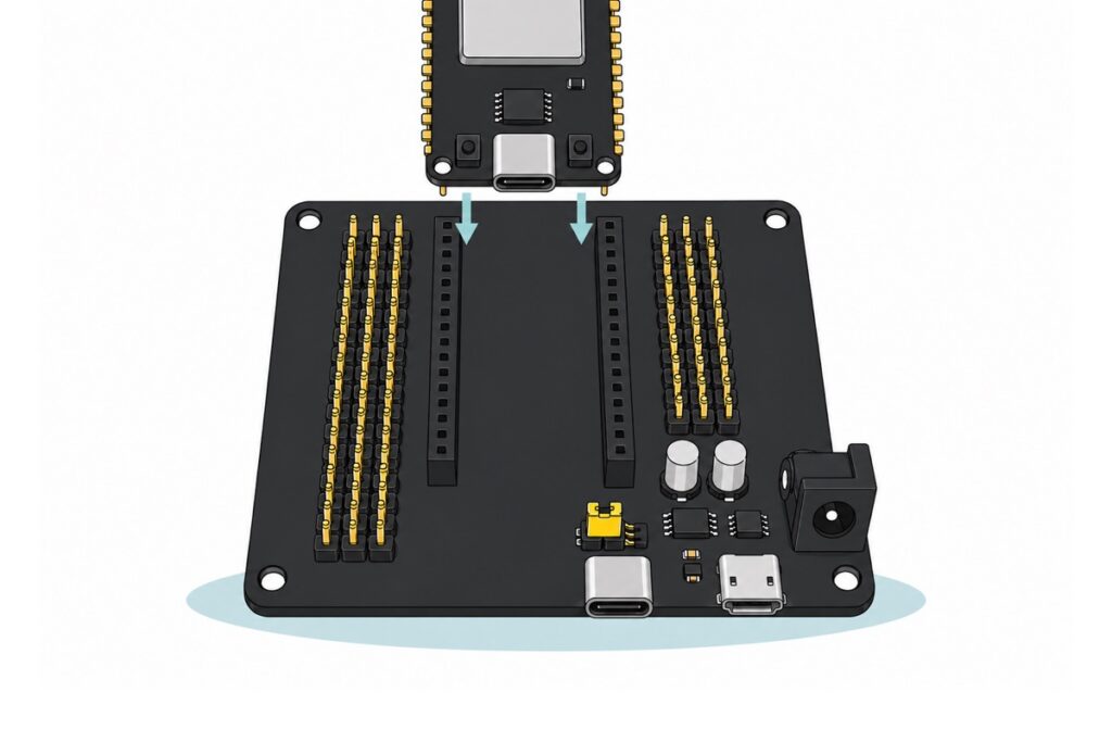
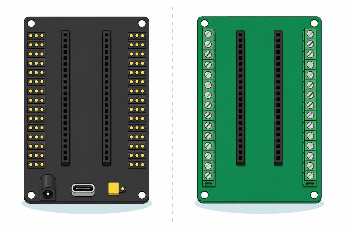
The ESP32 30P expansion board holds a 30-pin DevKit in the two black socket rows down its middle, and brings every pin those sockets swallow back out on the headers flanking them. Each pin arrives as a column of three on the 2.54 mm pitch your jumper wires already use — G for ground, V for supply, S for the signal — with its name printed beside it.
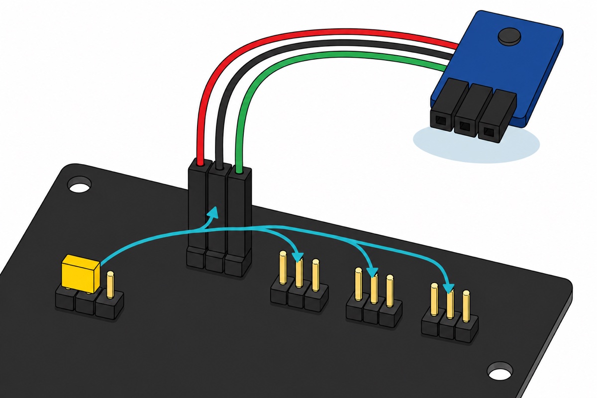
The V pin is where people misread this board. It is not a fixed 5 V and it is not a separate 3.3 V rail: it is one rail shared by every column, and a small yellow cap on the header marked JUMP decides whether that rail carries 5 V or 3.3 V for all of them at once. Beside that jumper, a separate supply header brings out 5 V and 3.3 V together with ground, and the manufacturer’s datasheet notes the selectable level reaches the I2C pins too.
Those G-V-S pins are male, and so are the pins on nearly every sensor module. Two male ends cannot mate, so the wires between them have to be female-to-female. The male-to-male jumpers in your drawer meet nothing at all on this board. Our jumper wire guide covers the three genders.
The pairing this guide is about
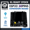 ESP32 Expansion Board 30P Expansion Board ESP32 Shield GPIO Expansion Development Kit
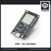 NodeMCU ESP32 Wi-Fi + Bluetooth Development Board CH340/CP2012 - For IOT Project - ESP-32 (CH340)
Parts list
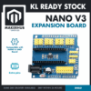 Nano Expansion Shield For Arduino NANO R3
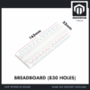 MB102 Breadboard 170 400 830 Holes Breadboard Donut Board Arduino Prototype Multi Color - BREADBOARD (830 HOLES)
 40pcs Dupont Wire 10cm 20cm 30cm for Breadboard DIY Experiment Jumper Wire Breadboard wire - DUPONT WIRE M-M 20CM
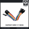 40pcs Dupont Wire 10cm 20cm 30cm for Breadboard DIY Experiment Jumper Wire Breadboard wire - DUPONT WIRE F-F 20CM
Three separate lanes, not one basket. If you took the expansion board above, the female-to-female jumpers are the row you actually need — its headers are male, so male-to-male wires meet nothing. If your board is an Arduino Nano rather than an ESP32, the Nano expansion shield is the same idea for that footprint. If you decided against a carrier entirely, the 830-hole breadboard and male-to-male jumpers are the route that replaces it.
Why does a 30-pin ESP32 DevKit fight a breadboard?
The 30-pin ESP32 DevKit V1 is exactly as wide as a full-size breadboard’s entire grid, and that one measurement is the whole problem. Count the geometry across an 830-hole breadboard: five holes each side of the centre channel at 2.54 mm pitch, and a channel 0.3 in wide. The outermost hole of one half therefore sits 0.4 + 0.3 + 0.4 = 1.1 in from the outermost hole of the other. The DevKit’s two pin rows are 1.1 in apart — eleven 2.54 mm pitches, 27.94 mm. Same number.
So the DevKit’s pins land in the outermost column on each side, and its circuit board lies flat across every remaining hole in those rows. Electrically those holes are still joined to the pin above them; physically you cannot get a jumper into one, because a board is sitting on top of it. Not “not enough room” — no reachable hole at all, on either side. How a breadboard works explains which holes are joined.
What does the expansion board fix on power, and what does it not?
The expansion board carries exactly one regulator, rated 5 V at about 1 A, and its type decides how to feed it. The part is a three-terminal 1117-family chip in an SOT-223 package with a big heat tab, between two 47 µF electrolytics — and there is no inductor anywhere on the board. A step-down switching converter cannot work without one, so this is a linear regulator: it does not convert the surplus voltage, it burns it as heat.
Espressif asks you to budget at least 500 mA for an ESP32-WROOM-32. At 12 V into the barrel jack, the regulator turns (12 − 5) × 0.5 = 3.5 W into heat. The AMS1117 datasheet puts the best-case path from junction to air at 46 °C/W against a 125 °C junction limit, so in a 25 °C room the package sheds roughly 2.2 W — and 46 °C/W flatters a board this size. So 12 V asks a package that can shed about 2.2 W to shed 3.5 W, and the thermal shutdown that follows reads exactly like the brownout you bought the board to cure. At 7.5 V in, the same 500 mA costs 1.25 W. The silkscreen prints DC6.5-16V, but the 1117’s own absolute maximum input is 15 V and the board’s own datasheet calls the socket 6-15 V. That datasheet’s 7-12 V is where to work, and you want the bottom of it.
It does fix one real failure. The DevKit’s own 3.3 V regulator needs roughly 4.4 V at its input to hold 3.3 V under load, because a 1117 loses about 1.1 V across itself at high current. Send 5 V down a thin two-metre USB lead while the radio pulls a few hundred milliamps and it can arrive as 4.3 V — the board resets, or never boots. A 7.5 V supply into the barrel jack has volts of headroom to lose first, and the DevKit’s VIN pin gets its 5 V through a centimetre of copper instead. Judge that with the USB lead out, though: two 5 V sources land on one node and the higher one wins, so a tethered DevKit is probably still running on USB.
Now the honest half. Move the yellow cap to 3.3 V and nothing on the expansion board feeds that rail — the shield has one regulator and it makes 5 V. The 3.3 V comes back up out of the DevKit’s own 3V3 pin, from the small regulator on the DevKit itself. Your 3.3 V budget after fitting the shield is exactly your budget before it. A project that resets when Wi-Fi transmits has a 3.3 V problem this board does not touch; powering ESP32 projects does.
There is no level shifting either. A column’s S pin is a plain copper trace from the header to the socket pin, and that socket pin is the ESP32’s GPIO. Espressif caps a high-level input at the IO supply rail plus 0.3 V — 3.6 V on a 3.3 V ESP32. Put the cap on 5 V, power a 5 V sensor from the V rail, and its output swings to about 5 V — 1.4 V past the limit, with nothing in between. The rail selector is a convenience, not a translator.
This walkthrough meters the supply pins on the 38-pin sibling of this board — same idea, a footprint that does not fit these sockets:
Will this board fit yours? Count the pins first
The 30P expansion board takes a 30-pin DevKit and nothing else, so the check takes five seconds: count the pins along one long edge of the board in your hand. Not a photo — 30-pin and 38-pin ESP32s look nearly identical, and the pin count is the only reliable tell.
| Your board | Pins per long edge | Fits the 30P expansion board? |
|---|---|---|
| ESP-32 (CH340), USB-C | 15 | Yes — this is the pairing |
| ESP-32 (CP2102), micro-USB | 15 | Yes |
| ESP-32S, 38-pin | 19 | No — sockets are the wrong length and spacing |
| Arduino Nano V3 | 15 | No — different footprint entirely |
A 38-pin ESP-32S is not stranded, it takes a different accessory: the ESP32 terminal adapter is a green carrier with a screw terminal for every pin — the same trade, in a form that takes bare wire. Still choosing? Which ESP32 variant settles that first.
The idea is not ESP32-only: the Nano expansion shield does the same job for an Arduino Nano V3, dropping it into two centre sockets on a blue Uno-shaped board and returning every pin as a yellow three-pin G-V-S block.
How do you check the board is seated properly?
Press the DevKit in with its USB connector facing the same end as the expansion board’s own USB sockets, then prove the wiring rather than assume it. This sketch blinks the onboard LED on GPIO2 and slowly toggles the column marked D5.
// Shield seat check. Proves the expansion board's header columns really are
// wired to the ESP32 pins their silkscreen names, before you trust any wiring.
const int LED_ONBOARD = 2;   // the onboard LED silkscreened D2 on the 30-pin DevKit V1
const int TEST_PIN    = 5;   // the header column silkscreened D5 on the shield

void setup() {
  Serial.begin(115200);
  pinMode(LED_ONBOARD, OUTPUT);
  pinMode(TEST_PIN, OUTPUT);
  Serial.println("Black probe in the G hole of the D5 column, red probe in S.");
  Serial.println("S must swing 0.0 V and 3.3 V, once a second, never 5 V.");
  Serial.println("Move the red probe to V: that is 5.0 V or 3.3 V, whichever");
  Serial.println("the yellow JUMP cap selects. The S pin does not follow it.");
}

void loop() {
  digitalWrite(LED_ONBOARD, HIGH);
  digitalWrite(TEST_PIN, HIGH);   // GPIO5 driven to 3.3 V
  delay(1000);
  digitalWrite(LED_ONBOARD, LOW);
  digitalWrite(TEST_PIN, LOW);    // GPIO5 pulled to 0 V
  delay(1000);
}
A driven S pin reads 3.3 V even with the rail cap on 5 V — rail and signal are independent, so a 5 V rail never turns your outputs into 5 V outputs. One trap lives along the far edge: the columns marked VP, VN, D34 and D35 are GPIO36, 39, 34 and 35, and those four ESP32 pins are input-only. Repoint TEST_PIN at one and nothing will ever move. Keep them for sensors that produce a signal.
A second trap arrives with the convenience: every column is equally reachable, so a module lands on whichever one is nearest — and D12 is a strapping pin the ESP32 reads once at power-up. Held high as the board boots it tells the chip the flash runs at 1.8 V, and a 3.3 V flash part then refuses to start. Booted fine bare, dead once the headers were populated? Unplug D12 first.
When is a plain breadboard the better answer?
A plain breadboard wins often enough to say so from behind the counter. For one sensor and an LED, three female-to-female jumpers pushed straight onto the DevKit’s pins cost less than the carrier and take no space. Two breadboards pushed together side by side give the DevKit a free row on each side, if the hole pitch carries across the join. And a circuit built mostly from loose passives needs breadboard rows, which a carrier does not give you — it hands you headers, so most builds want the breadboard either way.
Common mistakes we see
Buying the 30P board for a 38-pin ESP-32S. The two look almost the same in a photo. Count 15 or 19 pins along one long edge before ordering; a 38-pin board wants the screw-terminal adapter.
Expecting it to cure a Wi-Fi brownout. Resets when the radio transmits are a 3.3 V problem, and every 3.3 V milliamp still comes from the regulator on the DevKit.
Bringing male-to-male jumpers. The columns are male pins and sensor modules are male pins, so the wires between them must be female at both ends — the commonest reason a new expansion board sits unused for a week.
Leaving the rail cap on 5 V with a 3.3 V sensor. One cap sets every column’s V pin, so a 3.3 V-only module sees 5 V on its supply pin — and may answer with a 5 V signal into a 3.6 V GPIO.
FAQ
What does an ESP32 expansion board actually do?
It holds a 30-pin ESP32 DevKit in two centre sockets and brings every pin out on 2.54 mm headers as a three-pin column — ground, supply, signal — with the pin’s name printed beside it, plus a barrel jack and a 5 V regulator.
Does an ESP32 expansion board fix brownouts or add more current?
Partly. Its 5 V regulator lets you feed the DevKit from a wall supply through a barrel jack instead of a thin USB cable, which fixes 5 V starvation. It adds nothing on 3.3 V — that rail still comes from the DevKit’s own regulator, so a board that resets when Wi-Fi transmits will still reset.
Can I connect a 5 V sensor to an ESP32 expansion board?
Not safely — the board has no level shifting. Each column’s signal pin is a direct trace to the ESP32’s GPIO, and Espressif caps a high-level input at the IO supply rail plus 0.3 V, which is 3.6 V on a 3.3 V ESP32. A 5 V sensor output is about 1.4 V past that. The 5 V rail powers modules; it does not protect the chip from them.
Do I need an ESP32 expansion board, or is a breadboard enough?
A breadboard is enough for one or two connections, or a circuit built mostly from loose passives, since a carrier gives you headers rather than rows. The expansion board is worth it when several three-wire modules are involved, when the project runs from a wall supply, or when someone else must find the right pin later.
Last updated September 2026. Stuck? Chat with us on WhatsApp.
