

Tutorials
How a Breadboard Works: Hidden Holes and Which Size to Buy
Sep
A breadboard — in Malay, papan roti, literally “bread board” — is the white perforated plastic board that joins components without soldering, and its secret is a hole map you cannot see: every group of five holes inside it is ONE metal clip, so those five holes are one and the same electrical point.
This guide covers where the name came from, the hole map under the plastic, which size (170, 400 or 830) suits which project, and the mistakes that most often kill a beginner’s circuit.
Why do Malaysians call a breadboard “papan roti”?
“Papan roti” is a straight translation of the English bread board, and the English name began as a board that really did cut bread. In the early radio days, enthusiasts nailed copper wire and circuit parts to the cheapest flat piece of wood in the house — the kitchen bread board (Adafruit, the history of the breadboard name). The nails became terminals, wire was wound between them, and there was your temporary circuit.
The wood disappeared long ago; the name stayed. The technical terms “experiment circuit board” and “prototyping board” exist, but in the shop and the school workshop, papan roti is the word everyone uses.
What is really connected inside a breadboard?
A breadboard’s white plastic connects nothing — it is only the housing. The joining is done by thin springy metal clips (usually phosphor bronze) hidden under the surface. Each clip is folded into five pairs of jaws, one pair beneath each hole; push a component leg in and that pair springs open and grips it against the same piece of metal.
Everything follows from there. The five holes above one clip are not five separate connections — they are a single electrical point. A resistor leg in hole 12a and a wire end in hole 12e are connected because both touch the same clip, even though no wire is visible between them.
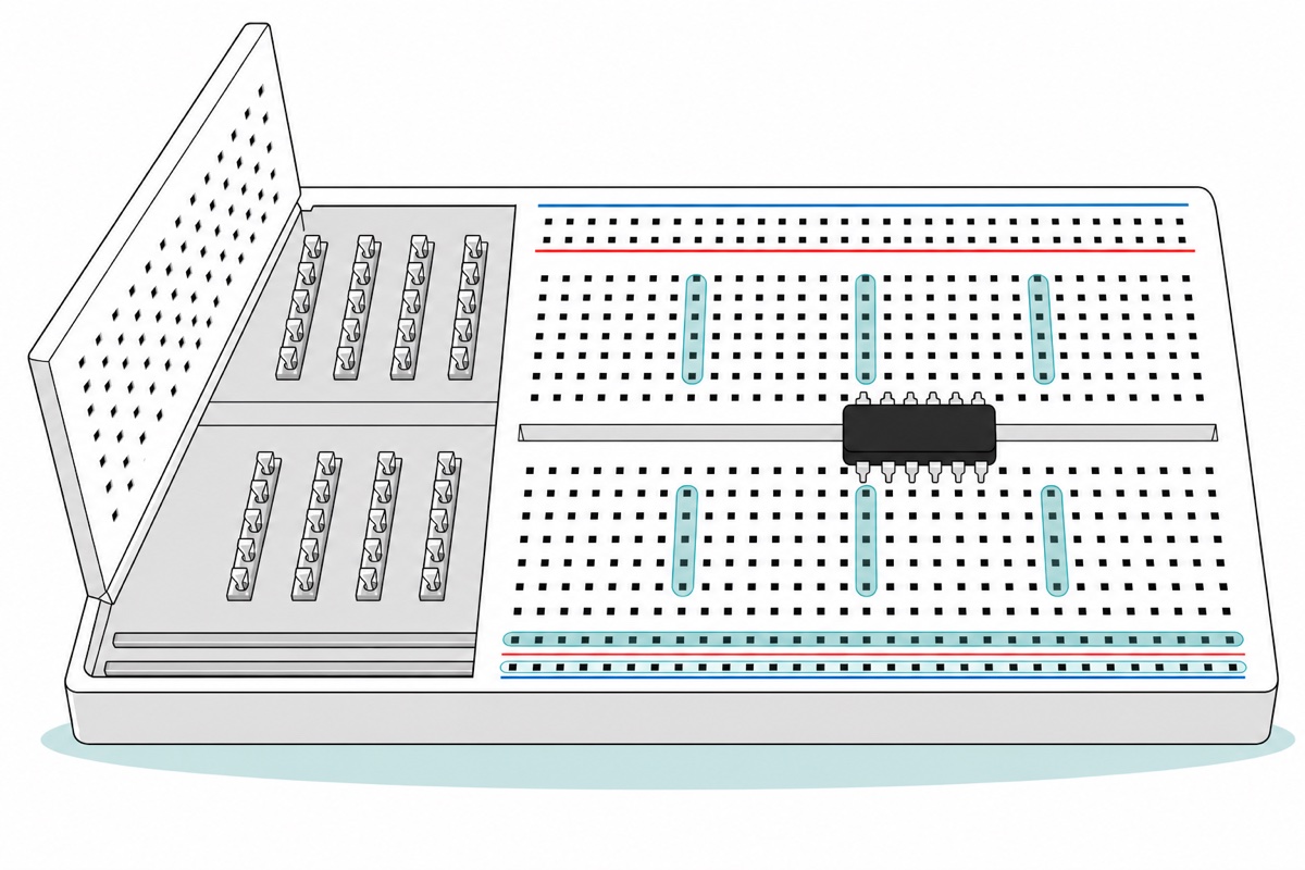
Those clips stop at the centre channel; the far side is a wholly separate set. The reason is the DIP-packaged IC. A DIP chip’s legs sit 2.54 mm apart along a row, and its two rows sit 7.62 mm apart (DIP16 300 mil package drawing, Nexperia SOT38-4). Breadboard holes share that 2.54 mm pitch, and a column-e hole is 7.62 mm from the column-f hole across the channel — exactly three pitches. Straddle the chip over the channel and every leg lands on a clip of its own. Were the clips to cross the channel, each leg would be shorted straight to the leg opposite it and no IC could be used.
The long stripes down the board’s edges are the power rails — one long metal clip that makes that whole row of holes a single point. The use is simple: an Arduino has only one 5 V pin, and one wire from it to the red stripe turns that pin into dozens of access points along the board.
| Part of the board | What is connected | What is NOT connected |
|---|---|---|
| Short row in the main field | The five holes in one row, e.g. 12a–12e | Any other numbered row, even the adjacent one |
| Centre channel | Nothing — it is a divider | Columns a–e do not reach columns f–j |
| Red / blue edge stripe | That stripe’s full length as one point — unless the printed line breaks in the middle, as on the 830 | The red stripe does not reach the blue stripe |
| The board’s two edges | Each edge stands on its own | The top edge rails do not reach the bottom edge rails |
This beginner’s walkthrough from Moritz Klein shows real hands pushing component legs in and testing which rows connect — motion that is hard to convey in text.
170, 400 or 830 — which size for which project?
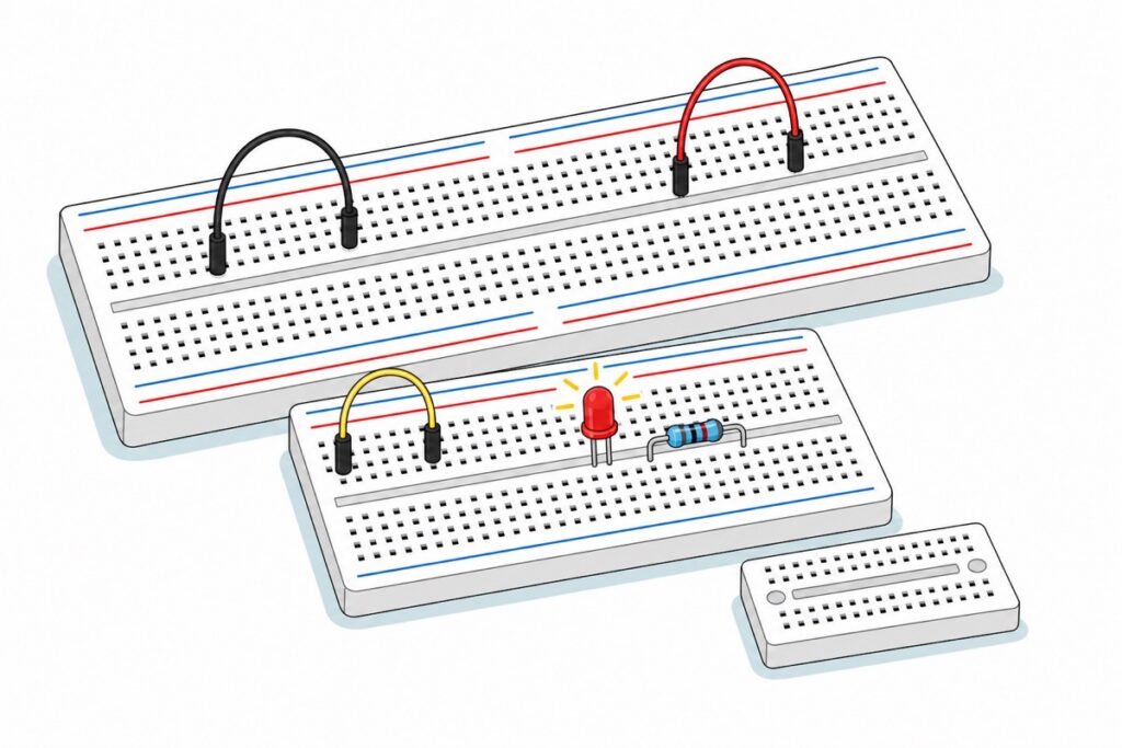
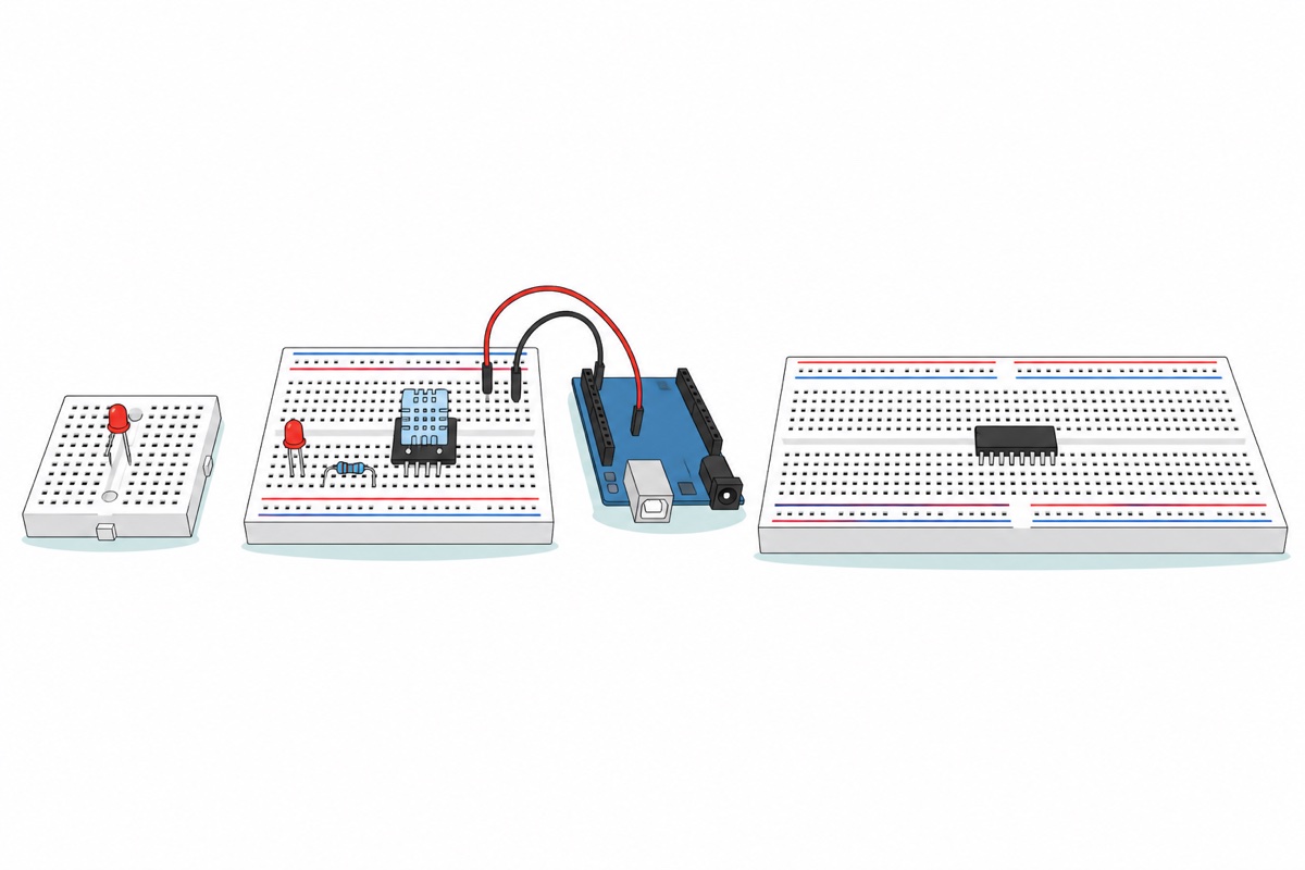
Breadboards are named after their total hole count, and that number alone tells you whether the board has power rails. The 170-hole mini board has 17 rows in the main field, and 17 × 10 = 170 exactly. Every hole is spent in the main field, so nothing is left over for rails — a mini board has no power rails at all, just a long centre channel and two screw holes.
Boards and wires for breadboard work
 MB102 Breadboard 170 400 830 Holes Breadboard Donut Board Arduino Prototype Multi Color - BREADBOARD (400 HOLES)
 MB102 Breadboard 170 400 830 Holes Breadboard Donut Board Arduino Prototype Multi Color - MINI BREADBOARD 170 HOLES (WHITE)
 MB102 Breadboard 170 400 830 Holes Breadboard Donut Board Arduino Prototype Multi Color - BREADBOARD (830 HOLES)
 Breadboard Jumper Wire Set with Casing 140 pcs / 560 pcs For Arduino Prototyping Application - 140 PCS JUMPER WIRE KIT
 40pcs Dupont Wire 10cm 20cm 30cm for Breadboard DIY Experiment Jumper Wire Breadboard wire - DUPONT WIRE M-M 20CM
The three board sizes above are ALTERNATIVES, not one set - take only one, using the size table below. The M-M dupont wires are what join Arduino headers to breadboard holes; the 140 pcs set is stiff solid-core wire for tidy runs on the board itself.
Do the same arithmetic on the 400-hole board: 30 numbered rows × 10 holes = 300 in the main field, and the remaining 100 are the four rail stripes along its two edges. The 830-hole board grows that field to 63 rows: 63 × 10 = 630 in the main field, plus 200 rail holes along the two edges, and that is 830. Its printed numbers stop at 60 because markers are printed only every fifth row — three more rows follow 60 carrying no number, and those three complete the count.
One naming note before you buy: the code MB-102 in our listing title is the family name of this standard breadboard, and the power module that plugs into its rails is also called MB-102. A search for “MB102 breadboard” can lead to two completely different things, so check the photo before adding to cart.
Now count how many rows your project really eats. An Arduino Uno does not sit on top of the breadboard — it sits beside it, joined by wires. One sensor module straddles four or five rows, a resistor two, an LED two. An “Uno plus one sensor” project rarely passes ten rows, and a 400 board gives you three times that — which is why 400 is most people’s default.
Module width decides the choice too, not just row count. A row has only five holes each side of the channel, so a module straddling the channel with closely spaced pin rows still leaves a few free holes for wires, while a wide one — many ESP32 development boards included — can land right out at the end column and leave not one hole beside it. When that happens, clip two boards together by their side tabs so each pin row lands on a different board.
The 830 earns its place when a lot must be alive at once: one 16-leg DIP chip already eats eight rows, add a display and two or three modules and 30 rows gets tight. The mini is for small finished things — its back is adhesive for sticking inside a project box, and the side tabs on every board let two or three clip together side by side.
| Board | Physical size | Main-field rows | Power rails | Suited to |
|---|---|---|---|---|
| Mini 170 (BRB170H) | 47 × 35 mm | 17 | None at all | Small finished circuits stuck inside a box |
| 400 (BRB400H) | 85 × 55 mm | 30 | Yes, full length, unbroken | An Uno with one or two sensors |
| 830 (BRB830H) | 165 × 55 mm | 63 (numbered to 60) | Yes, but split in the middle | DIP chips, a display and several modules at once |
Why is the 830 board’s power rail broken in the middle?
The 830 board prints the answer on its own face. Look at the red and blue stripes along the edge of our 830: the line stops and starts again with a blank gap roughly at the middle of the board. That is not a printing fault but a standard marking, and it means that edge rail is not one long metal clip but two separate clips end to end.
Manufacturers break it deliberately so one board can carry two voltages — 5 V on the left half, 3.3 V on the right, say. For anyone who does not know, it makes the most convincing “faulty board” there is: feed 5 V into the red stripe at the left end and the left-hand circuit lights up, while the right-hand circuit on that same red stripe has no voltage at all.
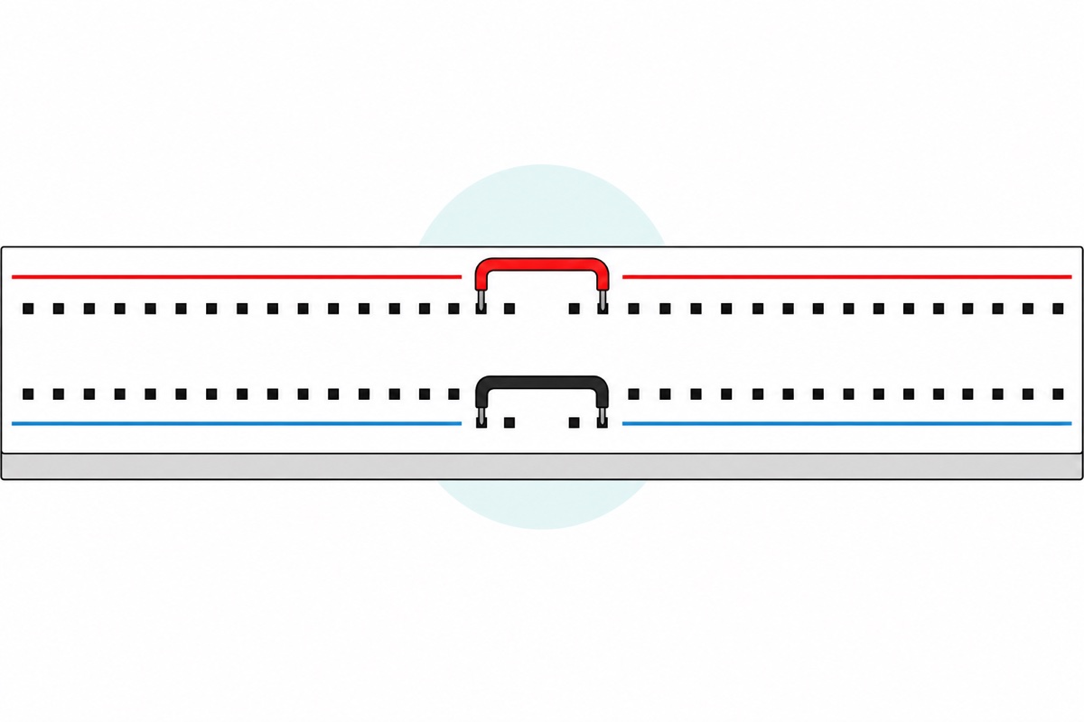
The rule is simple: where the printed line breaks, assume the metal inside breaks too. To make it one full rail again, plug a short wire across that gap on the red stripe and another on the blue, on both edges of the board. Confirm it once on a new board: continuity mode on a digital multimeter answers in five seconds — one probe in the leftmost red-stripe hole, the other in the rightmost. A beep means that rail is one continuous clip; silence means it is split and needs bridging. Repeat for the blue stripe and the other edge. Our 400 board has no such problem — its red and blue stripes run the full length with no gap.
Optional: breadboard power module
| Item | Price | Qty | |
|---|---|---|---|
 MB-102 Breadboard Power Supply Module 3.3V 5V Direct Plug In Bread Board For Arduino PowerBRBPOWE MB-102 Breadboard Power Supply Module 3.3V 5V Direct Plug In Bread Board For Arduino PowerBRBPOWE | RM3.95 |
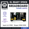
This MB-102 module plugs straight into two pairs of board rails through the + and - pins at its four corners, and those pins span the width of the board - so it fits a 400 and an 830 alike, because both are 55mm wide. Each side has its own yellow 5V / OFF / 3.3V jumper selector, so a rail left on OFF looks exactly like a faulty board. Input is 6.5-9V DC through the barrel jack, or 5V through the USB-A socket; maximum output 700mA. The 170 mini has no rails at all - there you take 5V, 3.3V and GND from its male header block with dupont wires.
The BRBPOWE power module shows that fit is decided by the board’s width, not its length. The four pairs of + and − pins at its corners span from one edge’s pair of rails to the opposite edge’s, so their spacing is locked to the board’s width — and look at the table above: the 400 and the 830 are both 55 mm wide. The module plugs straight into either. Only length differs: on a 400 its body covers more than a third of the board, so many people still prefer to take 5 V, 3.3 V and GND from its header block with dupont wires. The 170 mini has no rails at all, so that header block is the only route.
Which wires are right for a breadboard?
Breadboard holes accept pins, and the headers on an Arduino board are female sockets. That settles the answer: to join an Arduino board to a breadboard you need wire that is male at both ends, which is the flexible M-M dupont wire with a black plastic sleeve at each end.
The 140 pcs jumper wire kit is a different tool, not a substitute. Its wire is stiff solid core, cut to fixed lengths and bent 90 degrees at both ends so it lies flat on the board. Its job is hole-to-hole links on the board itself, and the result is a flat circuit you can read back later, rather than the dupont bird’s nest that hides mistakes. There is a 560 pcs set too.
M-F wires are for male-pinned modules that sit off the board — dupont M-F 20cm joins them straight to the Arduino headers without going through a breadboard. The full difference between male, female, Dupont and JST is in our jumper wire types guide.
Common mistakes we see
Two component legs in the same five-hole row. Put both resistor legs into holes 12a and 12c and both grip the same metal clip — that resistor is no longer a resistor in the circuit, just a shorted-out wire. Every component must span from one numbered row to another. The signs: an LED that flares blindingly bright for a second then dies, or a silent circuit though every wire looks right.
Powering a rail that is not connected. Besides the 830’s rail halves above, the second form happens on the mini board: a 5 V wire pushed into an edge row assumed to be a rail. The mini has no rails, so that wire powers only the four remaining holes in that one row of five.
Two power sources whose grounds never meet. The moment you plug a power module into the rails while the Arduino board is still running from its USB cable, that circuit has two sources. Every digital signal is a voltage difference measured against GND, so if the module’s GND and the Arduino’s GND are not joined, a sensor on the board shares no reference point with the pin reading it — readings turn to nonsense, or nothing happens. One wire from the Arduino’s GND pin to the blue stripe solves it, and that wire is compulsory for any second power source, not just this module.
Using a breadboard for motors and high-current loads. A breadboard connection is a spring jaw pressing on a component leg — a small contact area, with far higher and far less predictable resistance than solder. At high current, heat forms exactly at that contact point, the heat softens the spring, the grip loosens, and the situation gets worse on its own. Motors, heating elements and high-power LEDs belong on screw terminals or soldered joints — see stepper vs servo vs DC motors.
Forcing thick or stranded wire in. The jaws inside the board are springs, and a spring stretched past its limit does not come back. Solid wire that is too thick stretches it permanently, and that hole loses its grip for good — a dead hole that looks perfect from outside. Stranded wire, meanwhile, splays apart and will not go in at all. Our boards accept 20–29 AWG, and the usual size for breadboard work is 22 AWG solid core, about 0.64 mm — stick to that if you cut your own wire. Dupont wires do not break this rule: what enters the hole is not their stranded wire but the solid metal pin crimped on the end. This Science Buddies video shows how to spot loose connections the eye alone cannot see.
When should you stop using a breadboard?
A breadboard is built for circuits that will be pulled apart again, not for circuits that will be used. Every connection rests on spring pressure with no strain relief, so vibration or one knocked wire can break the circuit without leaving a sign. Once a circuit runs and you want it to stay that way, move it onto a donut board and solder it — the steps are in our donut board soldering guide. If Arduino is still new to you, start with the Arduino beginner’s guide first.
FAQ
What is a breadboard called in Malay?
A breadboard is called “papan roti” in Malay, a direct translation of the English bread board. The formal terms are papan litar percubaan (experiment circuit board) or papan prototaip (prototyping board), but papan roti is what is used in shops and school workshops. The name goes back to the early radio days, when enthusiasts nailed wire and components to a kitchen bread board.
Does a 170-hole mini breadboard have power rails?
No. The 170-hole mini has 17 rows in the main field, and 17 times 10 is exactly 170 — the total is spent in the main field, so nothing is left for power rails. What it does have is a long centre channel and two screw holes. The 5 V and GND wires must be run directly to each row that needs them.
Which breadboard size for an Arduino Uno and one sensor?
The 400-hole board. An Arduino Uno sits beside the breadboard, not on top of it, so the only things eating rows are the sensor and small components: one sensor module four to five rows, one resistor two rows, one LED two rows. A project like that rarely passes ten rows, while the 400 board has 30.
Why doesn’t my circuit work even though the wiring matches the picture?
Four causes cover most cases. First, two legs of one component sit in the same five-hole row, shorting that component out. Second, two legs are assumed connected across the centre channel, which in fact separates two sets of metal clips. Third, on an 830, power is fed into one rail half that is not connected to the other. Fourth, power comes from a source other than the Arduino but the two grounds were never joined. A continuity test confirms the first three; one GND wire fixes the fourth.
Can I use a breadboard for a motor?
Not recommended. A breadboard connection is a spring jaw pressing on a component leg, and its contact resistance is far higher and far less predictable than solder, so heat forms right at that contact point and loosens the grip of the spring itself. Motors, heaters and high-power loads should go through screw terminals or soldered joints.
Last updated September 2026. Stuck? Chat with us on WhatsApp.

Pingback: Small 5V DC Fan or Fan Module? How to Choose and Drive It