

Tutorials
Remote Control Car RBT Project: IR, Bluetooth or nRF24L01?
Sep
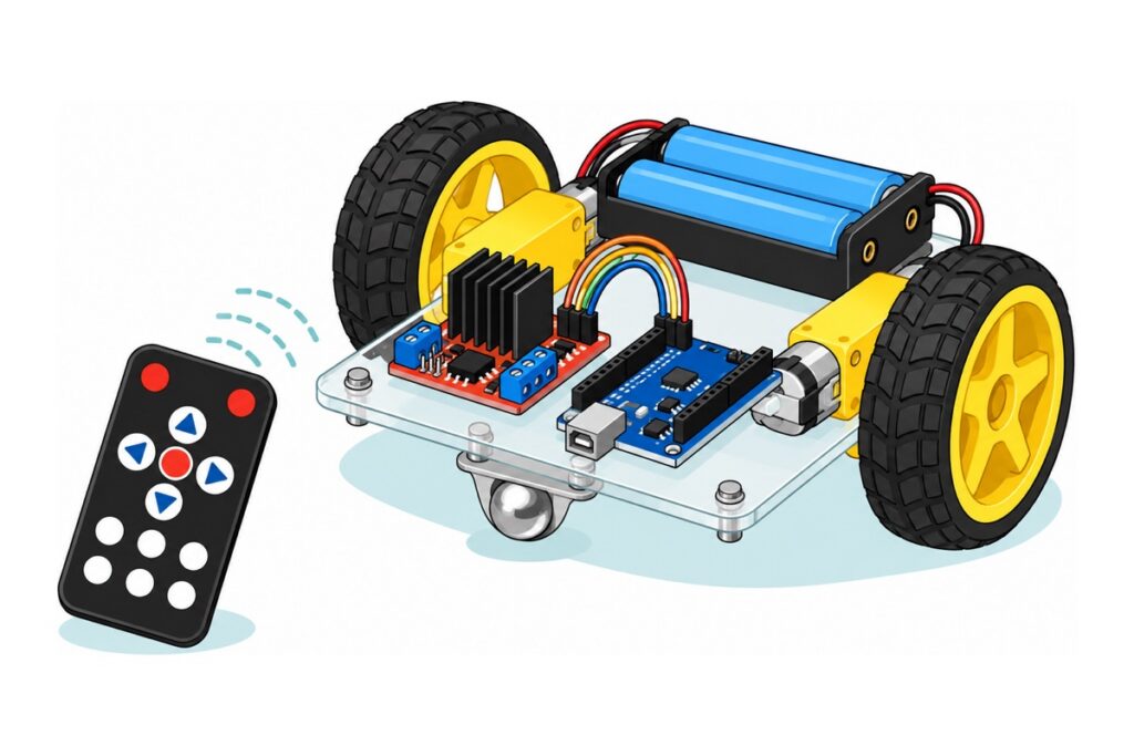
The RBT “Kereta Kawalan Jauh” (remote-control car) assignment for Year 6 and Form 3 usually asks for three things at once: a mechanical system that moves, a control system that can be driven from a distance, and a sketch or block diagram that explains both. For the remote-control half there are three honest routes — an IR remote, a phone over Bluetooth, or a pair of nRF24L01 radios. The IR remote is the fastest to finish for a school assignment, while a pair of nRF24L01s is the only one that gives you your own handheld controller — no aiming, no phone.
What does the “Kereta Kawalan Jauh” assignment actually ask of you?
The RBT assignment paper, whether Year 6 or Form 3, usually splits this project into three parts that are marked separately. The mechanical system is the physical thing: the base, the motors, the gears, the wheels and where the battery sits. The control system is the circuit that receives commands and turns the motors. The documentation is the design sketch, the block diagram and the report.
That is where the most common trap lies. Plenty of students spend all their time on the remote-control half and then hand in a car that was assembled in a rush: the battery pack strapped high with a rubber band, a base that flexes, one wheel loose. The mechanical marks vanish right there — and that is the easiest half to save, because it needs no code at all.
The same base car for all three control routes
 Arduino Uno Compatible SMD UNO R3 with Type B Cable - ATMEGA328P with CH340G-Microcontroller Project
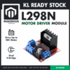 L298N Motor Driver Module Arduino Compatible Dual H Bridge Dual DC Motor Control Arduino Robotic Car
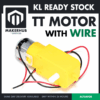 TT MOTOR WITH WIRE 3-6V DC 200RPM 1:48 GEARBOX MOTOR WITH WIRES PRE-SOLDERED
 200RPM TT MOTOR With 68mm Wheel 3V 5V 6V 9V Motor Plastic Gear Motor For Arduino Smart Car - WHEEL (FOR TT MOTOR)
 Ball Caster Wheel Ball Transfer Eye Ball Roller Caster Bull Eye Wheel For Arduino Smart Car
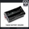 18650 Battery Holder 1/2/3/4 Slot 3.7V Battery Cell Housing Battery Case Battery Casing - 18650 BATTERY HOLDER (2)
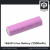 3.7V 18650 Battery Rechargeable Li-Ion Battery 1200mAh 2200mAh 3200mAh Flat Top - 18650 Li-Ion Battery (2200mAh)
 40pcs Dupont Wire 10cm 20cm 30cm for Breadboard DIY Experiment Jumper Wire Breadboard wire - DUPONT WIRE M-F 20CM
That is the car before you choose how to control it. The base itself is not included: you cut and drill it yourself from plywood, acrylic or stiff cardboard, and that is exactly the mechanical work that earns marks. The TT motors here come pre-wired — their red and black leads are soldered on at the factory — so this car needs no soldering at all.
The order of work goes like this, and it deliberately leaves remote control until last: (1) cut and drill the base, (2) fit the two motors, two wheels and the ball caster, (3) connect the L298N to the Uno and the battery pack, (4) test that the car drives straight using the test sketch below, (5) only then add the control route you chose, (6) draw the sketch and block diagram from the finished car. Steps 1 to 4 are identical whichever route you pick.
Three ways to make it move from a distance — which one for a school assignment?
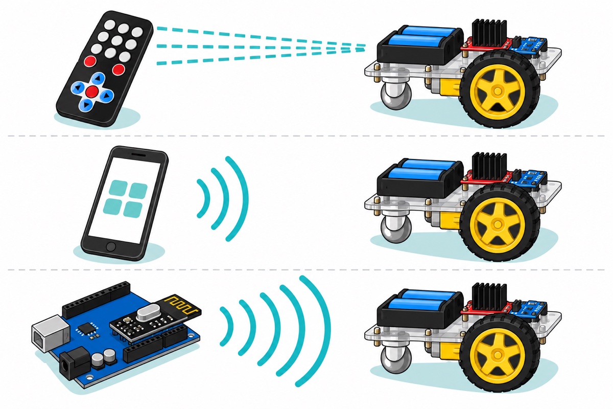
“Remote control” is not one technology: the three options below carry your command across the room in physically different ways.
An IR remote sends infrared light, not radio. When a button is pressed, the LED in the remote’s nose blinks about 38,000 times a second (38 kHz), and the HX1838 receiver on the car has a filter inside it that passes only light blinking at that rate. Sunlight is bright but steady, and room lighting flickers only about 100 times a second — both fall far outside the 38 kHz window, so the receiver will not mistake them for a signal. There are two costs. First, bright ambient light still lowers the receiver’s sensitivity, so range shortens next to a window or outdoors. Second, light does not bend. The remote has to be aimed straight at the receiver, range is 5 to 8 metres, and anyone standing in between breaks the link.
The HC-05 Bluetooth module changes technology entirely: it is a 2.4 GHz radio, so the signal passes through bodies and desks. The transmitter is the student’s phone running an app, so it costs nothing and there is no second circuit to build. Range is around 10 metres for a Class 2 module like this one. The cost: the demo depends on one phone that must be paired, and the teacher watches you holding a phone.
A pair of nRF24L01 modules is the only route that is genuinely remote control in the toy-car sense: one module in the car, the other in a handheld controller you build yourself. Both ends of the radio link are yours, so the range beats the other two routes comfortably — tens of metres in open space, less indoors. The cost is double the work: the controller needs its own second Uno board, its own power and its own code.
| Control route | What transmits | Typical range | Difficulty | Cost | What the teacher sees |
|---|---|---|---|---|---|
| IR remote (HX1838) | The remote in the box, coin-cell powered | ~5–8 m, must face it — light does not bend | Easiest — one signal pin on the Uno | Cheapest | A real remote in your hand |
| Bluetooth (HC-05) | The student’s phone + an app | ~10 m, passes through bodies and desks | Medium — install an app and pair the phone | Middle | You holding a phone |
| nRF24L01 radio (two modules) | A handheld controller you built | Tens of metres in open space | Hardest — two circuits, and both modules must run on 3.3 V, not 5 V | Dearest — needs a second Uno | A controller you built yourself |
For most school assignments the IR route wins. If your marking scheme mentions innovation or controller design, the nRF24L01 gives you more to show — order two modules and one more Uno board. Within the nRF24L01 family, the external-antenna version is the long-range member; the PCB-antenna module here is plenty for a school hall.
Pick ONE control route only
 HX1838 IR Remote Control Set Infrared Receiver Module Kit with Remote Controller for Arduino Pi DIY Projects
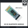 Wireless Bluetooth Module HC-05 HC-06 Master Slave Bluetooth Module HC05 HC06 - HC-05 BLUETOOTH MODULE
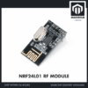 High Performance NRF24L01 RF Wireless Transceiver Module Antenna 2.4Ghz 1100m - NRF24L01 RF MODULE
The HX1838 set arrives complete with the remote, three jumper leads and a transmitter LED — have a CR2025 coin cell ready and pull out the plastic insulating tab under the remote before demo day. The Bluetooth route uses the student's phone as the transmitter. The nRF24L01 route needs TWO modules and a second Uno board for the handheld controller.
The mechanical system: which parts actually earn marks?
The TT motor used on school project cars is the 1:48, 3–6 V type, turning roughly 200 revolutions per minute at 6 V with no load. The 1:48 figure means the motor shaft inside spins 48 times for every single turn of the output shaft that holds the wheel. Gears trade speed for torque: a bare DC motor spins at thousands of rpm but its torque is far too small to push a car from standstill, while the gearbox multiplies that torque by roughly the same ratio.
That number gives you the car’s speed directly. One turn of a 68 mm wheel moves the car by its circumference, π × 68 mm ≈ 214 mm; at 3.3 turns per second (200 ÷ 60) the car travels about 0.7 metres per second — roughly half walking pace, and slower still under load.
Two TT motors drive the two rear wheels, and the ball caster at the front makes the car a tricycle. It steers by turning one wheel faster than the other, or in the opposite direction — no steering linkage, no servo. The ball caster has to roll freely; if it drags, the car veers even when both motors run at the same speed.
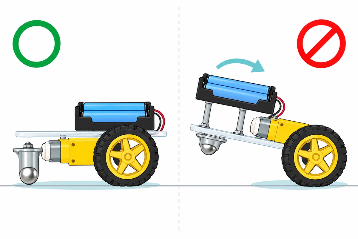
Two things on a home-made base need to be measured, not guessed. The first is height. Fit the two motors and their wheels first, stand the base on a table, then measure from the table to the underside of the base — that is the height the front ball caster has to fill. A 16 mm ball with its flange is almost always shorter than that, so add standoffs, spacers or a thin slip of wood underneath until the base sits level. Without that spacer the nose tips up, the ball never touches the floor at all, and the car spins on the spot.
The second is alignment. Both motors must sit on the same straight line and square to the base. Tie each motor down with two cable ties through holes you drill, or screw through the existing holes in the TT motor body, and check the alignment before you tighten. A car that curves when it should drive straight almost always starts here, not in the code.
Seeing the motors screwed down and the wheels pressed onto the shafts helps before you drill your own base:
Where the battery pack sits is physics, not decoration, and it is the real answer to “how do I stop the car tipping over”. The friction a tyre can push against is proportional to the weight pressing on it, and a two-cell 18650 pack is the heaviest thing on the car. Put it forward over the ball caster and that weight moves off the driving wheels, so the tyres slip on tiles. Put it high and the centre of gravity rises: when the car starts or stops sharply, the pack’s inertia rotates the car about its wheel axis until the nose lifts and the ball caster loses contact. Put the pack low and directly over the two driving wheels, and both problems disappear at once.
Optional: a ready-made chassis kit, if a bought base is allowed
 2WD 4WD Smart Car Chassis Single Layer Acrylic Arduino Smart Car Chassis Kit With Motor - 2WD CAR KIT
The 2WD kit is the classic two-wheel chassis with a pre-cut acrylic base, motors, wheels and ball caster. The 4WD kit uses four motors and no ball caster — two motors per side wired in parallel to one L298N channel, so the code stays the same. Check the assignment paper first: cutting and drilling the base yourself is often the part that earns the marks.
Why a 7.4 V pack and not four AA batteries?
The L298N module does not hand the whole pack voltage to the motors. Each motor is fed through two transistors in series inside the chip — one pulling one motor terminal towards the supply, the other pulling the opposite terminal to ground — and each of them drops its own voltage. The ST L298 datasheet lists that total drop as at least 1.8 V and up to 3.2 V at 1 A.
Two 18650 cells in series in a two-slot holder give 7.4 V nominal, so after the L298N drop the motors see about 5.5 V — right inside the TT motor’s 3–6 V range. Four AA batteries give 6.0 V fresh and sag further under load, leaving the motors around 3 V: the car moves on the table, then fails to climb a door threshold on demo day. The holder wires its cells head-to-tail so they are in series — follow the + and − marks moulded into the plastic.
New 18650 cells arrive only part-charged, so plan how you will charge them before demo day. An 18650 is a lithium cell: never solder directly onto the cell body, never short its terminals, and charge it with a proper lithium charger as in the TP4056 18650 charging guide. This whole project stays on low-voltage DC and no part of it goes anywhere near mains power.
How do you know the mechanical system is right before adding remote control?
The mechanical system is tested separately from the control system. The sketch below has nothing to do with IR, Bluetooth or radio — it simply drives the car forward, backward and turning in a fixed sequence. If the car cannot drive straight with this sketch, no control route will fix it.
| L298N module pin | Connect to | Note |
|---|---|---|
| ENA | Uno D9 | Pull the jumper cap off ENA first, or the speed stays locked at full |
| IN1 / IN2 | Uno D4 / D5 | Left motor direction |
| IN3 / IN4 | Uno D6 / D7 | Right motor direction |
| ENB | Uno D10 | Pull the jumper cap off ENB too |
| OUT1 / OUT2 | Left motor | Swap these two wires if the direction comes out reversed |
| OUT3 / OUT4 | Right motor | Same |
| VS (+12V terminal) | Red wire of the 7.4 V pack | |
| GND (middle terminal) | Black wire of the pack and the Uno’s GND | One common ground — the single most commonly forgotten wire |
| +5V terminal | Uno 5V pin | Leave the 5V jumper fitted as long as the pack stays below 12 V — the module’s 5 V regulator then powers the Uno. Above 12 V that jumper must come off and the Uno be powered separately, or the regulator burns out. This connection also bypasses the Uno’s own regulator, so upload the code first and unplug the USB cable before you make it |
The last two rows of that table end at screw terminals, not at pins. The female socket on the end of a Dupont wire cannot be clamped by a screw, so cut the female end off two of the wires and strip about 5 mm of copper there; the male end that remains plugs into the Uno’s socket as usual. The battery pack’s red and black wires are already bare copper and go straight into the VS and GND terminals.
Upload the sketch below through the Uno’s USB Type-B socket — the squarish printer-style socket, not micro-USB — and pull the pack’s red wire out of the VS terminal every time you do. With the 5 V jumper fitted, the module’s regulator and the computer’s USB power meet on the same 5 V rail: upload on USB alone, unplug the USB, then reconnect the pack.
// MECHANICAL SYSTEM TEST ONLY - there is no remote-control system here.
// The car runs a fixed sequence so you can judge the base, the tyres,
// the motors and the battery-pack position before adding IR, Bluetooth
// or nRF24L01. Board: Arduino Uno. Driver: L298N.

const int ENA = 9;    // left motor speed  (PWM)
const int IN1 = 4;    // left motor direction
const int IN2 = 5;
const int IN3 = 6;    // right motor direction
const int IN4 = 7;
const int ENB = 10;   // right motor speed (PWM)

// D9 and D10 share the same timer on the Uno, so both speed channels
// behave alike. Do not move ENA or ENB to D5 or D6: the Arduino
// analogWrite reference warns that pins 5 and 6 produce a higher duty
// cycle than the one requested, so the two wheels would not match at
// low speed.
// analogWrite sets the percentage of time power is connected, not the
// voltage, so 180 out of 255 means the motor receives roughly 70% of
// the voltage available. On a freshly charged pack (8.4 V) that keeps
// the motors near their 6 V rating, and the car is slow enough to watch.
const int LAJU = 180; // 0-255. Start at 180, not 255.

void kuasa(int kiri, int kanan) {
  analogWrite(ENA, kiri);
  analogWrite(ENB, kanan);
}

void berhenti() {
  kuasa(0, 0);
}

void keDepan() {
  digitalWrite(IN1, HIGH); digitalWrite(IN2, LOW);
  digitalWrite(IN3, HIGH); digitalWrite(IN4, LOW);
  kuasa(LAJU, LAJU);
}

void keBelakang() {
  digitalWrite(IN1, LOW); digitalWrite(IN2, HIGH);
  digitalWrite(IN3, LOW); digitalWrite(IN4, HIGH);
  kuasa(LAJU, LAJU);
}

void pusingKanan() {  // left wheel forward, right wheel backward
  digitalWrite(IN1, HIGH); digitalWrite(IN2, LOW);
  digitalWrite(IN3, LOW);  digitalWrite(IN4, HIGH);
  kuasa(LAJU, LAJU);
}

void setup() {
  pinMode(ENA, OUTPUT); pinMode(IN1, OUTPUT); pinMode(IN2, OUTPUT);
  pinMode(ENB, OUTPUT); pinMode(IN3, OUTPUT); pinMode(IN4, OUTPUT);
  berhenti();
  delay(3000);        // time to set the car on the floor and step back
}

void loop() {
  keDepan();     delay(2000);
  berhenti();    delay(1000);
  keBelakang();  delay(2000);
  berhenti();    delay(1000);
  pusingKanan(); delay(1000);
  berhenti();    delay(3000);
}
Put the car on the floor, not on a table. This sketch repeats forever and there is no switch fitted, so the way to stop it is to pull the red wire out of the VS terminal — know that before you let the car go. Watch for one thing: does it drive straight? If it curves, the cause is almost always mechanical — one motor not parallel to the base, one wheel not pushed fully onto its shaft, or a dragging ball caster. How to trim each motor’s speed with PWM is covered in the L298N DC motor speed guide.
The pins chosen above deliberately leave room for all three routes. Once the L298N has taken D4 to D7, D9 and D10, what remains is D2, D3, D8, D11, D12, D13 and A0 to A5. An IR receiver needs one data pin. The HC-05 needs two SoftwareSerial pins — use D2 and D3, not D0 and D1, because those two are shared with USB and uploads fail while the module is connected. The nRF24L01 needs D11, D12 and D13 for SPI plus two more pins for CE and CSN. None of them clashes with the motor driver, so your test car never has to be rewired.
Only then fit the control route you chose — the full wiring and code live in Bluetooth RC car with HC-05, IR remote with HX1838 and a pair of nRF24L01s. More ideas are in our list of RBT electronics project ideas.
What must your sketch and block diagram show?
The design sketch and block diagram for this remote-control car are not a drawing tutorial, and we will not pretend to teach you how to draw. What we can tell you exactly is what the diagram has to contain.
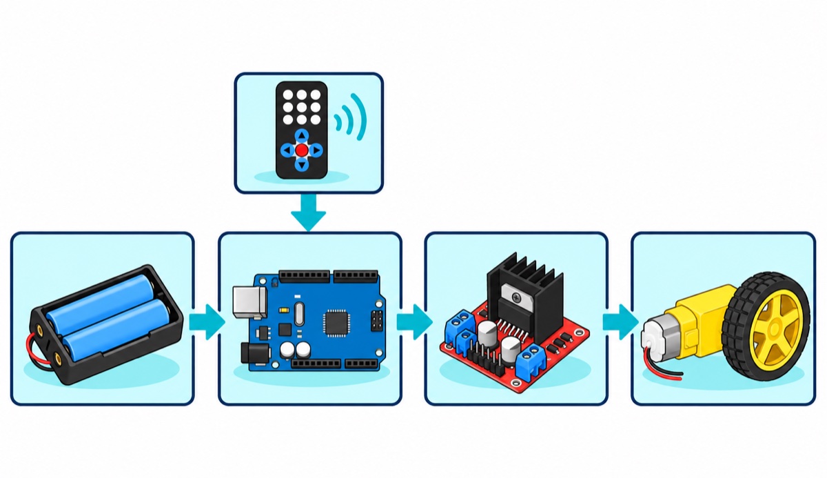
An RBT block diagram usually has to show four blocks in a chain, with arrows showing the flow: power source (the 7.4 V pack) → controller (the Arduino Uno board) → motor driver (the L298N module) → motors (the two TT motors and their wheels). Add one arrow entering the controller block from the side, labelled as the wireless signal — that is the control route you chose.
One thing gets drawn wrong again and again: the power source does not go straight to the motors. It goes through the motor driver, and that is the whole reason a motor driver exists — the Arduino can give a signal but cannot give the current a motor needs. For the design sketch, draw a top view and a side view, mark where the battery pack sits on the side view, and label the base dimensions and the material of each part — that is what is usually asked for.
The report has one mark that is the easiest of all to collect: justification. Write down why you chose that control route, with the range, cost and difficulty of all three options set side by side as in the table above. A comparison you wrote yourself shows a design decision, not just a shopping list.
Common mistakes we see on remote-control car projects
No ground wire between the Uno and the L298N. The symptom is odd: the lights on both boards come on, but the motors either do nothing or move randomly. A digital signal is a voltage relative to ground; without a shared ground wire, “HIGH” from the Uno means nothing to the L298N.
The ENA and ENB jumper caps left fitted. The L298N module ships with small jumper caps tying the ENA and ENB pins to 5 V. While they are on, both motors are locked at full speed and your analogWrite does nothing at all. Worse, the wires from D9 and D10 now meet that 5 V rail directly: every time the Uno pulls those pins LOW, current flows back into the pin and can damage it. Pull both jumper caps off before you wire ENA and ENB.
The car spins on the spot when the code says forward. The two motors are mounted facing opposite ways, one to the left and one to the right, so the same voltage turns them in opposite directions as seen from outside the car. Swap the two wires of one motor only at the OUT terminals, and leave the code alone — this is a wiring problem, not a logic problem.
The car runs briefly, then the Arduino resets. As the 18650 pack drains, the 5 V regulator on the L298N module loses the voltage headroom it needs to hold a steady 5 V, and the Uno resets every time the motors draw a big current. The figure is around 7 V going in: a 2S pack that has dropped below that will reset the Uno even while the motors can still turn. Measure the pack with a multimeter and recharge the morning before the demo — this is not a faulty board.
The remote does nothing even though the code is right. The remote in an IR set ships with a plastic insulating tab under the coin cell so the cell does not drain in storage. Pull that tab out first, and keep a spare CR2025 cell in the project bag.
FAQ
What is a remote-control car in an RBT project?
A small car you build yourself with two parts that are marked separately: the mechanical system (base, motors, gears, wheels, battery position) and the control system (the circuit that receives wireless commands). Those commands come from an IR remote, a phone over Bluetooth, or a radio controller you built yourself.
How do you make a remote-control car for an RBT project?
Build the car first, the remote control second. Cut and drill the base, fit two TT motors with 68 mm wheels and one ball caster, connect both motors to an L298N module, power the L298N from a two-cell 18650 pack and share a ground with the Uno, then test that the car drives straight with the mechanical test sketch. Only after that, pick one control route — IR remote, Bluetooth over a phone, or a pair of nRF24L01s — and follow the wiring guide for that route.
Which route is easiest for a Year 6 RBT remote-control car?
The IR remote route. The remote is already in the HX1838 set’s box, there is no app to install, and there is no second circuit to build. The limit: the remote must be aimed straight at the receiver within about 5 to 8 metres, so plan the demo so the car drives towards you.
Why does my car move on the table but not on the floor?
Usually power or grip. The L298N drops 1.8 V to 3.2 V at 1 A, so a 6 V pack of four AA batteries leaves the motors only around 3 V — not enough to push the car. A two-cell 18650 pack (7.4 V) fixes it. If the voltage is already right, make sure the pack sits low and directly over the two driving wheels.
Do I really need two nRF24L01 modules for one car?
Yes. The nRF24L01 is a two-way radio: one module sits in the car, the other in a handheld controller that needs a second Uno board and its own power. That is why this route costs the most, and also why it is the only one that needs no aiming and no phone.
Can I use a ready-made chassis kit, or must I cut the base myself?
Both work, but cutting and drilling the base yourself is often the mechanical part that earns the marks, so check the assignment paper first. If a bought base is allowed, a 2WD kit gives you the acrylic base, motors, wheels and ball caster in one go.
Last updated September 2026. Stuck? Chat with us on WhatsApp.
