

Tutorials
micro:bit V2 School Projects: What’s Already on the Board
Sep
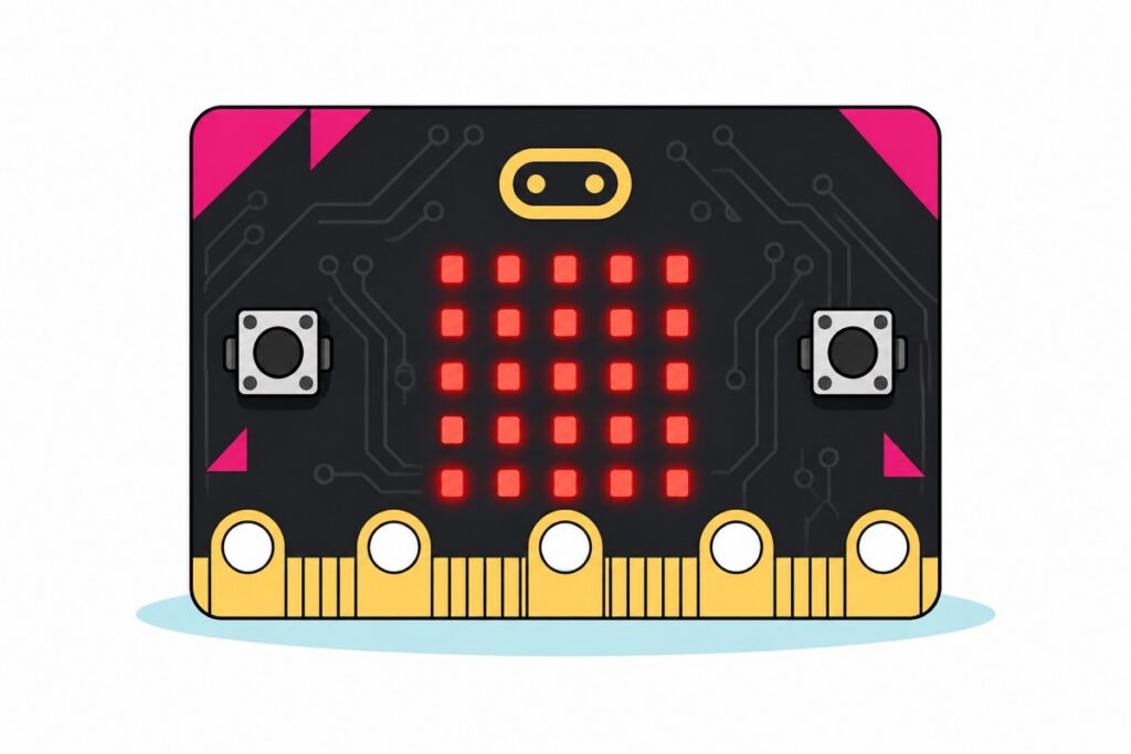
A micro:bit V2 board is already complete enough for a full RBT project without you buying anything else: a 25-LED display, two buttons, a touch logo, a microphone, a speaker, a light sensor, a temperature sensor, a motion sensor and a compass are all built in. No soldering, no wiring, and the program is written in a browser using MakeCode blocks.
What is already on the micro:bit V2 before you buy anything else?
The micro:bit V2 is a black circuit board about the size of a school badge, roughly 5 cm × 4 cm. Five large gold rings along its bottom edge are marked 0, 1, 2, 3V and GND — those are the points that take crocodile clips. On the back, the board’s own white silkscreen names what is inside it: MICROPHONE, SPEAKER, PROCESSOR, ACCELEROMETER, COMPASS.
Two of those “sensors” have no separate sensor component at all. The light sensor is the LED display itself: a reverse-biased LED acts as a weak photodiode, so the board drops one display frame every few frames — a pause of a few milliseconds, far too short for the eye to catch — charges some of the LEDs, and measures how fast that charge leaks away (the micro:bit runtime’s notes on light sensing). The brighter the room, the faster the leak. The temperature sensor sits inside the processor, so what it reads is the die temperature; because the board produces almost no heat of its own, that reading tracks room temperature closely but is not identical to it. Compare it once against an ordinary thermometer and record the difference in the report.
The board’s brain is a Nordic nRF52833, an Arm Cortex-M4 with 512 KB of flash and 128 KB of RAM (the official micro:bit hardware specification). The 256 KB figure still circulating in older reference material belongs to the V1 board and its nRF51822 chip — the V2 doubles it, and that headroom is what carries the audio processing.
| What is on the board | How it works | Use in an RBT assignment |
|---|---|---|
| 25-LED display (5×5) | The LEDs are scanned row by row, far too fast for the eye to see | Numbers, icons, scrolling messages, bar graphs |
| Buttons A and B + touch logo | Two mechanical switches; the gold logo senses touch through the capacitance of a finger | Menus, reset, three inputs without a single wire |
| MEMS microphone | Converts sound pressure into a voltage; MakeCode reports a level of 0–255 | Classroom noise meter, a clap as a trigger |
| Speaker | A small magnetic disc on the back of the board | Alarms, melodies, audio warnings |
| Accelerometer + compass | One combined chip (LSM303AGR or FXOS8700CQ; the runtime detects which one is fitted) measuring 3-axis acceleration and a 3-axis magnetic field | Step counter, shake dice, compass, tilt detector |
| Light sensor | The display LEDs used in reverse as photodiodes | Automatic lighting, day/night detector |
| Temperature sensor | A sensor inside the processor die | Room temperature logging, thermometer |
| 2.4 GHz radio + Bluetooth | A 2.4 GHz transceiver inside the nRF52833 itself; the zigzag gold track in the top corner of the board is its antenna | Two micro:bits talking to each other wirelessly |
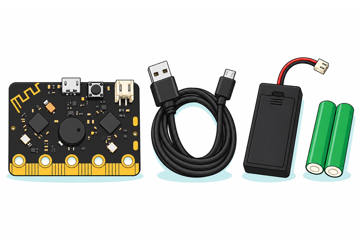
The only thing you must buy: a complete micro:bit V2 set (board, USB cable, battery holder and two AAA cells)
| Item | Price | Qty | |
|---|---|---|---|
 MicroBit V2.2 Go Bundle RBT Tahun 5 & 6 Junior Kit STEM Coding - MICRO:BIT NO BOXMCBV2UB MicroBit V2.2 Go Bundle RBT Tahun 5 & 6 Junior Kit STEM Coding - MICRO:BIT NO BOXMCBV2UB | RM92.00 | Out of stock |
Three RBT projects you can finish without a single extra component
All three micro:bit projects below run on the same bare board, in one program. The step counter uses the accelerometer: every step produces a sharp spike in acceleration, and MakeCode already wraps that spike up as a ready-made Shake event. The classroom noise meter uses the microphone, which gives a number from 0 to 255, and a bar graph on the 5×5 display makes it readable from the back of the room. The thermometer reads the sensor inside the processor and shows degrees Celsius.
The code below is the text view of those same blocks; the JavaScript button in the editor switches between the two views.
let langkah = 0

// Accelerometer: every shake detected counts as one step.
input.onGesture(Gesture.Shake, function () {
    langkah += 1
})

// Button A: show the step count so far.
input.onButtonPressed(Button.A, function () {
    basic.showNumber(langkah)
})

// Button B: show the temperature in degrees Celsius.
input.onButtonPressed(Button.B, function () {
    basic.showNumber(input.temperature())
})

// Touch logo: show the sound level (0-255) as a bar graph on the 5x5 display.
input.onLogoEvent(TouchButtonEvent.Pressed, function () {
    led.plotBarGraph(input.soundLevel(), 255)
})

// Press A and B together to reset the step count.
input.onButtonPressed(Button.AB, function () {
    langkah = 0
    basic.showIcon(IconNames.No)
})
To turn this into an RBT project rather than a demo, add one measurement: compare the board’s count against a hand count over 50 steps, then explain why it drifts. The Shake event is not a step detector — it only reports that the magnitude of three-axis acceleration crossed a fixed level, then goes quiet for a moment so that one shake is not counted twice. Walking slowly produces footfalls too soft to cross that level, so the board under-counts; swinging your arm, setting the board on a desk and running all cross it repeatedly, so the board over-counts. A real pedometer filters the acceleration reading until only the one-to-three-times-a-second rhythm is left, then counts peaks with a minimum spacing between them — a tidy improvement for a group chasing extra marks. Project ideas that use separate components are in our list of RBT electronics project ideas, and the primary-school report format is in the primary school science project guide.
Why micro:bit and not Arduino for Year 5 and 6?
The difference between the micro:bit and an Arduino is not about which board is more capable, but about how many obstacles stand between a pupil and a project that runs. With an Arduino, a simple sensor project means installing the IDE, installing a USB driver, picking the right board and port, then connecting at least three wires before anything happens. In a school computer lab that blocks software installation, the very first step ends the project.
The micro:bit removes all four obstacles: its sensors are already on the board, its editor runs in a browser, and the board appears as an ordinary USB drive with no driver to install. That convenience has a real price: micro:bit pins sit on a 3V rail with a limited current budget, so the moment a project needs a motor, a long LED strip or many cheap nodes, an Arduino becomes the right tool. For Year 5, Year 6 and lower secondary assignments, where the marks come from the idea, the data and the report, a micro:bit finishes the project inside one class period.
How does the program get onto the board?
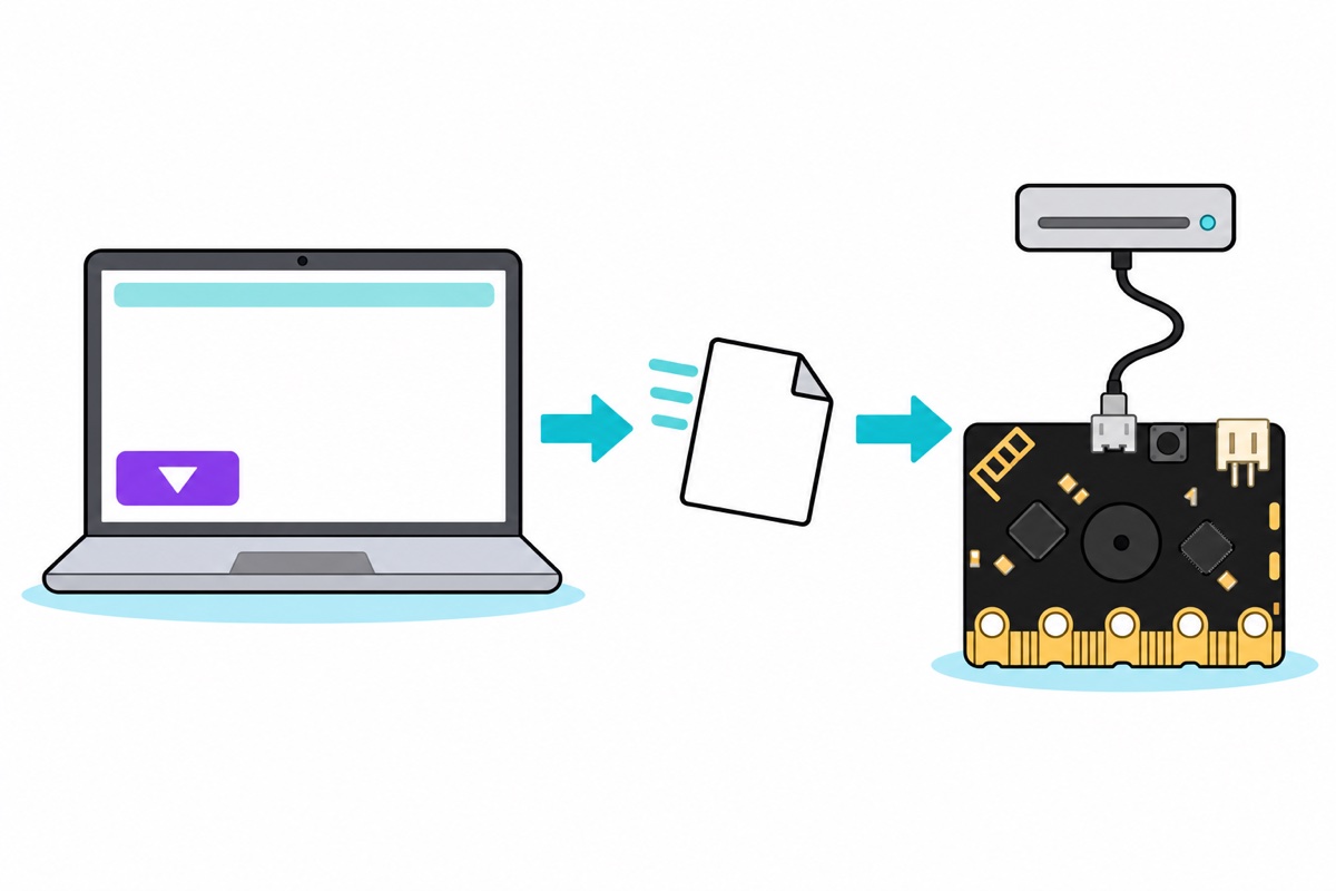
MakeCode installs nothing on the computer. Open the MakeCode editor for micro:bit in a browser, arrange the blocks, press Download, and the browser downloads a .hex file into the Downloads folder like any other file. Connect the board with a USB cable and it appears as a drive named MICROBIT in File Explorer or Finder. Drag the file onto that drive, and the program starts running as soon as the copy finishes. Even before the boards reach the pupils, the simulator on the left of the editor already runs those same blocks on screen, so a whole class can write and test its programs before every group is holding a board.
It works without a driver install because the micro:bit carries a second chip whose only job is to be the USB interface. That chip introduces itself as ordinary USB mass storage — the same device class as a pen drive — and Windows, macOS and ChromeOS have carried drivers for that class for decades. The .hex file is not really stored either: the interface chip reads it as it is copied, programs the main processor’s flash, then restarts the board. That is why the MICROBIT drive disappears and reappears after every upload, and why the file is not there when you open the drive again. The program itself lives in the processor’s flash, so it runs again every time the board powers up — on the battery holder, with no computer — until you write another program over it.
One detail that rescues a lot of school assignments: MakeCode saves projects inside that computer’s own browser, so on a shared or wiped lab PC the project can be gone by the next class. The downloaded .hex file is the backup copy — MakeCode embeds the source code inside that same file, so dragging an old .hex back into the editor restores the blocks (the micro:bit guide to saving your programs). Keep that file in Google Drive or on the pupil’s pen drive, not on the lab desktop.
Watching the step done helps before you try it in front of a class:
What do you add when the project has to move or make sound off the board?
As long as a micro:bit project only displays, measures and makes sound through the on-board speaker, nothing else is needed. The moment something has to turn off the board, two things change. First, those gold rings are only five connection points; the other 20 pins on the gold edge are too fine for crocodile clips and need an edge connector. Second, the board’s 3V rail offers only around 190 mA through the edge connector (the official micro:bit power supply notes), while a small servo draws far more when it starts moving and when it stalls. The cause is back-EMF: as a motor’s armature spins it generates a voltage opposing the supply, and that is what holds the current down. While the motor is still stationary — the instant a servo starts moving, or when its arm is held — that back-EMF is zero, so only the coil resistance is left to limit the current. And that 190 mA budget belongs to everything you connect, not to the servo alone.
The IOBIT V2 expansion board solves both. The micro:bit slides into its black edge socket, and every pin comes back out as three rows of servo-style pins — yellow for signal, red for power, black for ground — so a translucent-blue SG90 servo plugs straight in with no loose wires. Match the colours before you push it home: the servo’s orange wire on the yellow row (signal), red to red, and brown on the black row (ground). That three-pin plug fits either way round, and fitting it backwards puts power on the signal pin — the most common way a class servo dies. The board carries its own micro-USB and DC sockets, so the servo is fed from that external supply instead of being squeezed through the micro:bit’s 3V pin. It also adds a buzzer and a 3.5 mm audio jack on P0. One small thing that often eats time on presentation day: the board has a little slide switch on its top edge, next to the edge socket — if everything looks right but nothing comes alive, that is the first place to check.
For projects that stay on the five gold rings — traffic lights, home-made switches, touch detectors — crocodile clip leads are the classic accessory; when to use them instead of dupont wires is covered in the crocodile clip lead guide.
Optional additions for when the project has to move or make sound off the board
| Item | Price | Qty | |
|---|---|---|---|
 IOBIT V2.0 Micro:Bit Compatible Expansion Board MicroBit GPIO ExpansionIOBITV2 IOBIT V2.0 Micro:Bit Compatible Expansion Board MicroBit GPIO ExpansionIOBITV2 | RM25.00 | Out of stock | |
 SG90 MG90 Tower Pro Micro Servo Motor 9g 180 360 Servo Motor for Arduino Robotic - SG90- 180°SG90180 SG90 MG90 Tower Pro Micro Servo Motor 9g 180 360 Servo Motor for Arduino Robotic - SG90- 180°SG90180 | RM6.55 | ||
 Data Cable Type-A Type-C MicroUSB Type-B 0.5m 1m 30cm 0.3m 100cm Data Transfer Upload Code - MicroUSB CABLE (1.0M)ATMC100 Data Cable Type-A Type-C MicroUSB Type-B 0.5m 1m 30cm 0.3m 100cm Data Transfer Upload Code - MicroUSB CABLE (1.0M)ATMC100 | RM5.90 | Out of stock |
The IOBIT V2 expansion board so servos plug straight in and run on external power, a 180-degree SG90 servo, and a spare micro-USB data cable for presentation day.
micro:bit V2 Go “With Box” or “No Box” — which one for your class?
Both Go sets carry the same micro:bit V2.2 board and the same contents: board, battery holder, USB cable and two batteries. Only the packaging differs. The With Box set comes in the official BBC micro:bit retail box, a kraft-and-green box marked SINGLE — useful when the set is a gift, is stored unit by unit in a classroom cupboard, or is handed to a pupil to take home. The No Box set is the tidier choice when a whole class orders many sets at once.
Common presentation-day problems, and what causes them
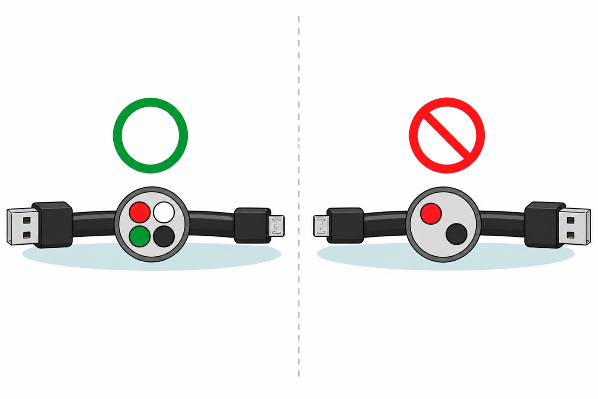
A charge-only cable. This is cause number one, and its symptom is specific: the small light on the back of the board comes on and the old program still runs, but the MICROBIT drive never appears. A full USB cable carries four conductors — power, ground and a pair of data lines — while the cheap cable that came with a desk lamp often carries only two. Power arrives, so the board lives; data never arrives, so the computer has no idea a device is plugged in at all. The cable in the micro:bit set is a data cable, and a 1.0 m micro-USB data cable is the right spare to keep in the project bag.
Weak AAA batteries. Two AAA cells in series give about 3.0 V when new, and alkaline cells do not die suddenly — their voltage sags slowly across their life. The LED display and the speaker are driven straight off that rail, so both go dim and sluggish long before the board stops entirely; that is your early warning. A cell’s internal resistance also rises as it nears the end, so the voltage dips a little further every time 25 LEDs and the speaker fire at once — which is why a multimeter can read a reasonable figure on a cell that can no longer run the board steadily. Use fresh alkaline AAAs, never mix old cells with new ones, and read the alkaline versus NiMH battery guide before choosing rechargeables.
The drive still does not appear, even with a data cable. Try another USB port directly on the computer rather than through a hub; cheap hubs often drop the voltage until the computer fails to recognise the board at all. If a drive appears under a name other than MICROBIT, the board is in firmware update mode because the reset button was held while the cable went in — unplug it, and plug it back in without touching the button.
The compass asks to be calibrated before it gives a reading. The first time a program reads the compass, the micro:bit runtime starts its own calibration: the display scrolls TILT TO FILL SCREEN and the board has to be tilted until all 25 LEDs are lit before any reading comes out (the micro:bit compass calibration guide). It is not a fault, but do it once before the presentation so the judges are not waiting out a tilting game first.
The simplest insurance for presentation day: leave the USB cable connected to a laptop or power bank even with the battery holder fitted. The micro:bit picks between the two sources through diodes that stop one source pushing current back into the other, so both are safe to connect at once. This board runs on 3 V and 5 V USB only — never connect it to mains power, and never let a crocodile clip bridge the 3V and GND rings.
FAQ
Is the micro:bit suitable for a Year 6 RBT project?
Yes, and that is the school level it fits best. There is no soldering, no wiring and no software to install, so the whole project can be finished inside a class period. The sensors are already on the board, so the assignment starts at the idea and the data, not at hunting for components.
Do I need to buy anything besides the micro:bit board?
Not for display, sound and sensor projects. A micro:bit V2 set already carries the board, a USB data cable, a battery holder and two AAA cells. You only need extras when something has to move or make sound off the board — an expansion board and a servo, for instance.
How do I get a program onto a micro:bit?
Open MakeCode in a browser, arrange the blocks, press Download to get a .hex file, connect the board with a USB cable, then drag that file onto the drive named MICROBIT. The program starts on its own. There is no IDE and no USB driver to install, so it works in school labs that block software installation.
Why does my micro:bit light up but the computer never shows a MICROBIT drive?
Almost always a charge-only cable. Cables like that carry only power and ground without the pair of data lines, so the board lives but the computer never knows a device is plugged in. Switch to a data cable, and try a USB port directly on the computer rather than through a hub.
Is a micro:bit or an Arduino better for a school project?
It depends on the assignment. The micro:bit wins when the marks come from the idea, the data and the report, because its sensors are built in and nothing has to be wired. An Arduino becomes the right tool the moment the project needs a motor, a long LED strip or many cheap nodes — that is where the micro:bit’s 3V rail becomes the obstacle.
Last updated September 2026. Stuck? Chat with us on WhatsApp.
