

Tutorials
Automatic Plant Watering Arduino Guide: Sensor to Pump
May
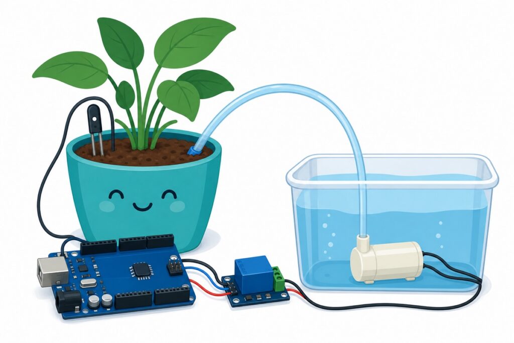
Yes — you can build an automatic plant watering system with an Arduino Uno in about an hour, with no soldering. The Uno reads a capacitive soil moisture sensor on A0, and when soil moisture drops below your calibrated threshold it switches a relay that runs a small 5V submersible pump. A safety timeout stops it flooding the pot.
How does an automatic plant watering system work?
The Arduino Uno sits in a simple sense-decide-act loop: the capacitive soil moisture sensor outputs a voltage that tracks water content, the Uno compares it against two calibrated thresholds, and a relay module switches the pump. It is the same pattern as our automatic clothesline rain sensor build — swap the sensor and the actuator, and the logic carries over.
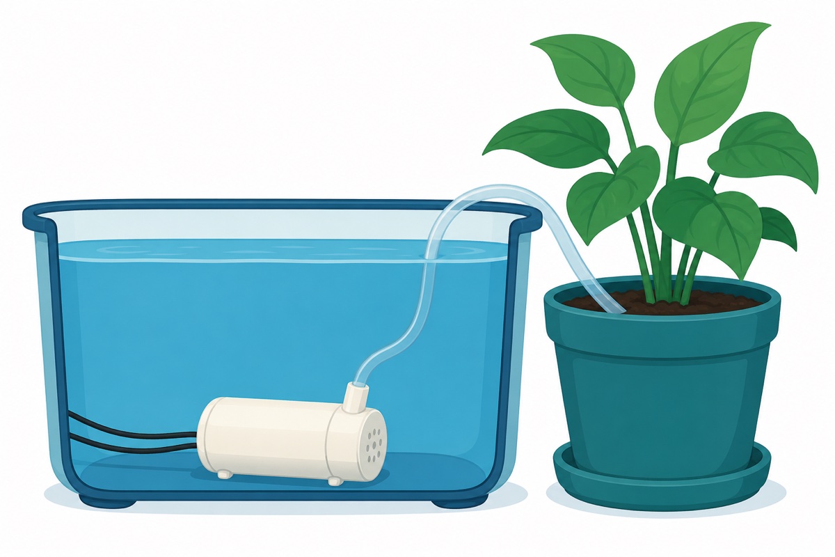
Water sits in any container — an old ice-cream tub works — with the pump inside and a silicone tube running to the plant. When the soil reads dry, the pump pushes water until the sensor reads wet again.
What parts do you need?
The Arduino Uno, capacitive soil moisture sensor, relay module and 5V pump — four modules make the entire build, joined by jumper wires plus the pump’s short tube. The Arduino Uno compatible (CH340G) is the brain; the sensor, relay and pump handle the input and output sides.
Parts list
 Arduino Uno Compatible SMD UNO R3 with Type B Cable - ATMEGA328P with CH340G-Microcontroller Project
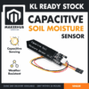 Capacitive Soil Moisture Sensor V1.2 Corrosion Resistant with Cable For Arduino IOT Application
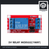 Relay Module 3.3V 5V 12V 1/2/4/8 Ways Optocoupler Trigger Relay Module 1 2 4 8 Channel Relay Module - 5V RELAY MODULE(1WAY)
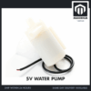 Mini Water Pump Submersible DC 3V-5V - 5V WATER PUMP
You will also want a USB power bank or spare 5V phone charger — the pump gets its own supply, and the wiring section explains why.
Why choose a capacitive soil moisture sensor over the two-prong fork?
The capacitive soil moisture sensor v1.2 (CAPSOIL) senses through its solder-mask coating, so no bare metal touches the soil. Cheap resistive forks pass current straight through damp earth, and electrolysis steadily eats their plating; for a build meant to run unattended, the capacitive probe simply outlasts them.
It runs from a 3.3–5.5V supply, but the output never swings rail-to-rail: powered at 5V, expect roughly 3V in dry air down to about 1.5V in water. Lower voltage means wetter soil, and every unit’s exact range differs — which is why calibration is a step, not an option.
One clone warning: some batches carry a 555 timer variant or regulator wiring that only behaves at 5V, or outputs close to the supply rail. On a 5V Uno this is harmless; just measure the output before trusting one on a 3.3V board.
How do you wire the sensor, relay and pump?
The 5V relay module (1WRELAY) is the bridge between the Uno’s brain and the pump’s muscle — never drive the pump from an Arduino pin. An Uno pin is rated for about 20mA continuous (40mA absolute maximum), while the relay coil alone draws around 70mA and the mini pump pulls in the region of 100–220mA with a bigger spike at start-up. The pin only signals the relay module; the heavy current flows elsewhere.
| Module pin | Arduino Uno pin | Purpose |
|---|---|---|
| CAPSOIL VCC (red) | 5V | Sensor power |
| CAPSOIL GND (black) | GND | Ground |
| CAPSOIL AOUT (yellow) | A0 | Analog moisture signal |
| 1WRELAY VCC | 5V | Relay coil and opto power |
| 1WRELAY GND | GND | Ground |
| 1WRELAY IN | D7 | Trigger signal (active LOW) |
On most opto-isolated relay boards the IN pin is active LOW — pulling IN to GND energises the relay — and the board already carries its own driver transistor and flyback diode, so the coil side needs no extra parts. The sketch assumes active LOW; if yours behaves inverted, swap the two constants at the top.
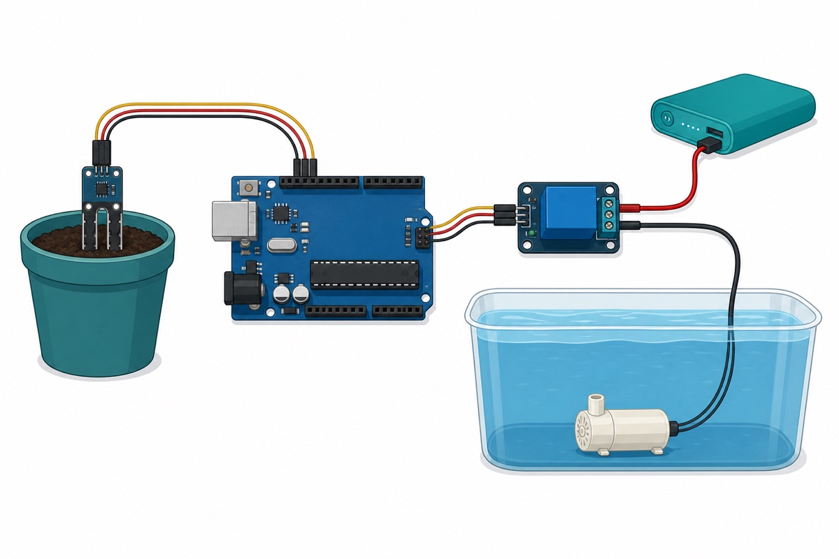
| From | To | Note |
|---|---|---|
| Power bank 5V (+) | Relay COM terminal | Pump supply enters the switch |
| Relay NO terminal | Pump red wire | NO = normally open, so the pump is off by default |
| Pump black wire | Power bank GND (−) | Completes the pump loop |
Power the mini submersible pump from that separate 5V source, not from the Uno’s 5V pin. Motor current spikes through the Uno’s regulator cause the classic “my Arduino restarts whenever the pump starts” bug. Because the relay contacts are electrically isolated, the pump loop does not even need to share a ground with the Uno.
Two placement rules: route the sensor cable away from the pump wires, since motor noise can wobble analog readings, and keep the pump fully underwater — it depends on water for cooling and must never run dry.
How do you calibrate the soil moisture sensor?
The capacitive soil moisture sensor never reads the full 0–1023 ADC range, and no two units read alike, so calibration takes two quick measurements. With the serial monitor open, note the raw value with the probe dry in open air (typically near 590 on a 5V Uno) and again dipped in a glass of water (typically around 270). Those two numbers become RAW_AIR and RAW_WATER in the sketch.
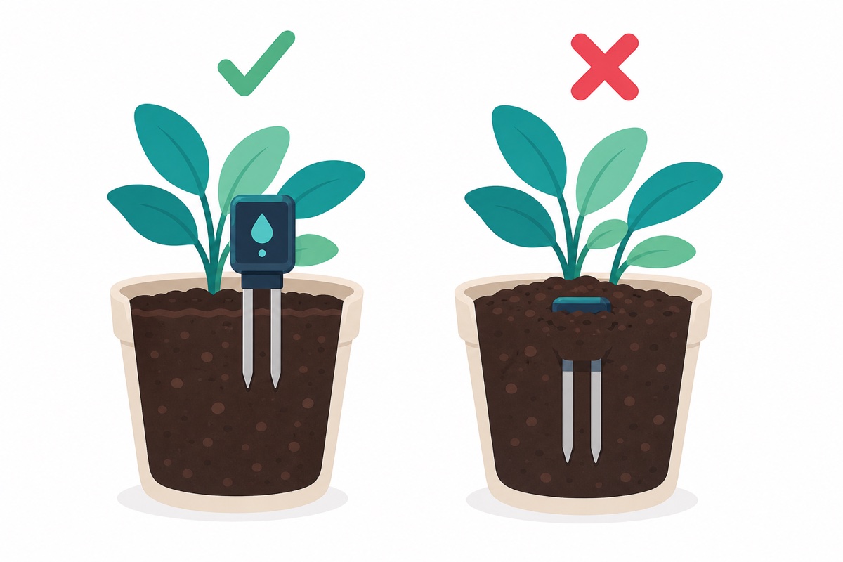
Push the probe in only up to the limit line printed across the PCB, keeping the SMD components above the soil and splash-free. Burying the electronics throws away the corrosion resistance you chose this sensor for.
What does safe watering code look like?
The Arduino sketch below waters on a band, not a single threshold: the pump starts when moisture falls under 35% and stops once it climbs past 55%. A single threshold makes the relay chatter on and off at the boundary; a band gives every watering a clean start and finish.
Three safety nets are built in. The pump runs for at most about eight seconds per cycle, waterings sit at least 30 minutes apart, and any reading outside the calibrated range locks the pump off — a disconnected sensor leaves A0 floating, which usually drifts out of that band. Water moves through soil slowly, so short pulses with rest in between beat one long soak.
// Automatic plant watering — Arduino Uno + capacitive soil sensor v1.2 + relay + 5V pump
// Sensor AOUT on A0, relay IN on D7. Most opto relay boards are ACTIVE LOW.

const int SENSOR_PIN = A0;
const int RELAY_PIN  = 7;

const int RELAY_ON  = LOW;   // swap these two if your relay board is active HIGH
const int RELAY_OFF = HIGH;

// ---- Calibration: replace with YOUR readings (see calibration section) ----
const int RAW_AIR   = 590;   // raw reading, probe dry in open air
const int RAW_WATER = 270;   // raw reading, probe in a glass of water

// ---- Watering band (hysteresis) ----
const int START_PUMP_BELOW_PCT = 35;  // drier than this -> start watering
const int STOP_PUMP_ABOVE_PCT  = 55;  // wetter than this -> stop watering

// ---- Safety limits ----
const unsigned long MAX_PUMP_MS = 8000UL;                // max 8 s pumping per cycle
const unsigned long MIN_GAP_MS  = 30UL * 60UL * 1000UL;  // at least 30 min between waterings
const int FAULT_MARGIN = 60;  // readings outside calibrated range +/- margin = sensor fault

bool pumping = false;
unsigned long pumpStartedAt  = 0;
unsigned long lastWateringAt = 0;

void setup() {
  digitalWrite(RELAY_PIN, RELAY_OFF);  // set OFF state before enabling the pin
  pinMode(RELAY_PIN, OUTPUT);
  Serial.begin(9600);
}

int readMoisturePct() {
  long sum = 0;
  for (int i = 0; i < 10; i++) {  // average 10 readings to smooth motor noise
    sum += analogRead(SENSOR_PIN);
    delay(20);
  }
  int raw = sum / 10;

  // A disconnected pin floats and can read anything -> treat as fault.
  if (raw > RAW_AIR + FAULT_MARGIN || raw < RAW_WATER - FAULT_MARGIN) {
    return -1;
  }
  // Lower raw = wetter. Map to 0 % (air-dry) .. 100 % (in water).
  int pct = map(raw, RAW_AIR, RAW_WATER, 0, 100);
  return constrain(pct, 0, 100);
}

void loop() {
  int moisture = readMoisturePct();
  unsigned long now = millis();

  if (moisture < 0) {  // sensor fault -> fail safe: pump locked off
    digitalWrite(RELAY_PIN, RELAY_OFF);
    pumping = false;
    Serial.println("Sensor fault - pump locked off");
    delay(5000);
    return;
  }

  if (!pumping) {
    bool dryEnough = (moisture <= START_PUMP_BELOW_PCT);
    bool rested    = (lastWateringAt == 0) || (now - lastWateringAt >= MIN_GAP_MS);
    if (dryEnough && rested) {
      pumping = true;
      pumpStartedAt = now;
      digitalWrite(RELAY_PIN, RELAY_ON);
    }
  } else {
    bool wetEnough = (moisture >= STOP_PUMP_ABOVE_PCT);
    bool timedOut  = (now - pumpStartedAt >= MAX_PUMP_MS);
    if (wetEnough || timedOut) {
      pumping = false;
      lastWateringAt = now;
      digitalWrite(RELAY_PIN, RELAY_OFF);
    }
  }

  Serial.print("Moisture: ");
  Serial.print(moisture);
  Serial.println(" %");
  delay(1000);
}
Prefer to watch a similar sensor-relay-pump build come together before you start? This walkthrough covers the same chain:
Common mistakes we see from real customers
Unlabelled sensor pins. “air sensor takde label VCC/GND/SIG” — some sensor batches ship with faint or missing silkscreen. On the cable bundled with the CAPSOIL sensor the usual convention is red = VCC, black = GND, yellow = analog out; if your colours differ, confirm which pad takes the supply with a multimeter before powering up.
Powering the pump from the Uno’s 5V pin. It looks fine on the bench, then the Uno resets mid-watering. Give the pump its own power bank or charger and the mystery resets disappear.
Using one threshold instead of a band. Right at the threshold the reading jitters a few counts, so the relay chatters rapidly on and off. The hysteresis band in the sketch exists precisely to prevent this.
Burying the sensor to the connector. The probe area is corrosion-resistant; the components at the top are not. Insert up to the limit line only, and keep watering splashes off the electronics.
FAQ
Can I use the capacitive sensor with an ESP32 or other 3.3V board?
Yes — the supply range is 3.3–5.5V. But because some clone batches misbehave below 5V or output near the supply rail, power the sensor first and measure its output, confirming it stays under 3.3V before wiring it to a 3.3V analog input.
Why does my pump keep running until the pot overflows?
Usually the sensor is not sitting in the zone the water actually reaches, so it never reads “wet”. Re-position the probe near the roots where the tube drips, and keep the MAX_PUMP_MS timeout in the sketch — it is the backstop that limits any single watering.
Can I run the whole system on battery?
A USB power bank can run both the Uno and the pump, though many power banks auto-sleep when the load is very small — test yours overnight. For a leaner 18650-based supply, see our TP4056 18650 charging guide.
Why does the relay click once when the Arduino boots?
The usual culprit is initialisation order: pinMode(pin, OUTPUT) drives the pin LOW by default, and on an active-LOW board that pulls the relay in until the OFF write lands. The sketch avoids this by writing the OFF state before enabling the pin, so the relay stays released through start-up; a brief click from the module itself as power comes up is harmless for a water pump.
Can the pump run dry?
No — the mini submersible pump relies on water for cooling and lubrication. Keep the intake below the water line, top up the tub before it empties, and let the pump timeout in the code limit the damage if the tub ever runs out.
Last updated August 2026. Stuck? Chat with us on WhatsApp.

Pingback: IoT Project Ideas for FYP: 10 You Can Finish Alone
Pingback: Mini Water Pump 3V-5V: How to Choose and Drive It