

Tutorials
Push Button Switch with Arduino: Wiring, Pull-Ups and Debouncing
Aug
A push button switch is not a component with a state — it is two springy pieces of metal that touch, and every problem you will have with one follows from that. Set the pin to INPUT_PULLUP, wire the switch to GND so pressed reads LOW, ignore the contact for 40 ms after it moves, and take an emergency stop from its normally closed pair.
Which switch do you need: momentary, latching, or maintained?
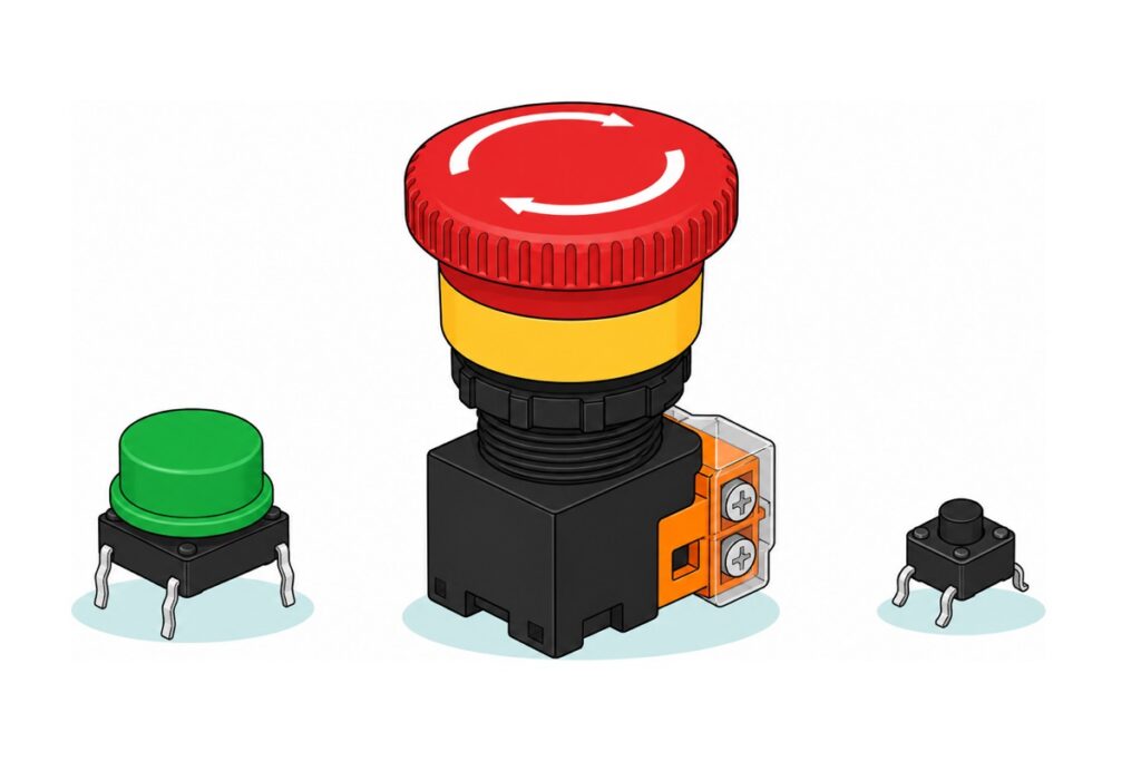
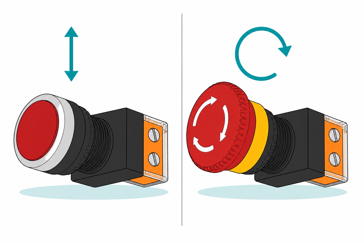
Push switches differ in exactly one property — what the contact does when you let go. A momentary switch springs back the instant you release it. A latching one stays down and needs a deliberate act to release: the LA38 emergency stop locks when it is struck and pops back only when the mushroom head is twisted, which is what the two curved arrows moulded into that head are telling you to do. A maintained switch stays where you flipped it.
The difference lands in your code, not in your wiring. A momentary button hands the Arduino an event: the sketch has to catch the moment of change and remember what it means. A latching or maintained switch hands it a condition: read the pin whenever you like and the answer is still true.
| Type | When you let go | Reads as | Example |
|---|---|---|---|
| Momentary (miniature) | Springs open | An event to catch | 6×6 tactile, 12×12 capped tactile |
| Momentary (panel) | Springs open | An event to catch | R13-507, LA38 flat-head |
| Latching | Stays pressed until twisted | A condition to read | LA38 emergency stop |
| Maintained | Stays where you flipped it | A condition to read | Rocker switch, E-TEN 1121 toggle |
| Electronic latching | Flips state on each touch | A condition to read | Bistable touch module |
Parts list — the raw-versus-debounced demo plus a real panel-mount e-stop
 Arduino Uno Compatible SMD UNO R3 with Type B Cable - ATMEGA328P with CH340G-Microcontroller Project
 MB102 Breadboard 170 400 830 Holes Breadboard Donut Board Arduino Prototype Multi Color - BREADBOARD (400 HOLES)
 40pcs Dupont Wire 10cm 20cm 30cm for Breadboard DIY Experiment Jumper Wire Breadboard wire - DUPONT WIRE M-M 20CM
 Tactile Button Momentary Switch 6mm x 6mm x 5mm Push Button 4 Pin
 Push Button with Cap Tactile Switch with Round Hat 12mm x 12mm x 7.3mm - PUSH BUTTON(GREEN)
 Industrial Emergency Momentary Button LA38 Push Switch RED Push To Stop Button - EMERGENCY BUTTON
Worth adding
 Industrial Emergency Momentary Button LA38 Push Switch RED Push To Stop Button - MOMENTARY BUTTON
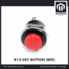 R13-507 Push Button Switch No-Locking Round Momentary Red Green Yellow Blue White Black - R13-507 BUTTON (RED)
 Data Cable Type-A Type-C MicroUSB Type-B 0.5m 1m 30cm 0.3m 100cm Data Transfer Upload Code - TYPE-A TO TYPE-B (1.0M)
The LA38 flat-head momentary uses the same 22 mm body and the same screw-terminal contact block as the emergency stop, so a pair of them teaches momentary versus latching on one product family. The R13-507 is the classic 16 mm panel button, but its two terminals are solder lugs — plan for an iron and a metre of wire, which our header-soldering guide covers. The spare A-to-B cable is the one that programs the Uno.
What do NO and NC mean, and why is every e-stop wired through NC?
Normally open and normally closed describe the contact at rest, with nobody touching it. An NO contact is open until pressed; an NC contact is closed until pressed. Nearly every small button is NO — the tactile switches, the R13-507. The LA38 family is the exception on this parts list: both the flat-head momentary and the emergency stop carry a contact block with one of each, an NO pair and an NC pair, each on its own screw terminals.
Now walk the failure. Take a machine’s stop signal from the NO pair: at rest the circuit is open, and pressing closes it to announce the stop. Cut the wire to that button and nothing observable changes — the circuit was already open. The button meant to save you is dead, and the only test that reveals it is pressing it in an emergency.
Take the same signal from the NC pair and the logic inverts. At rest the contact is closed, current flows, and the controller reads that flow as “everything is fine”. Press the head and it opens: stop. Cut the wire, back a screw out, knock the plug loose — also open, also stop. Every way the wiring can fail now lands on the safe side, which is the whole reason e-stops are NC.
Why does an Arduino read a button as pressed when nobody touched it?
An Arduino input pin measures voltage, and a switch at rest supplies none. A pin set to plain INPUT is joined to nothing but the chip’s high-impedance sense amplifier, so its voltage is decided by whatever stray charge reaches it — mains hum through your hand, the wire beside it switching. It reads HIGH, then LOW, then HIGH. That is a floating input, and the button that presses itself is always this.
The cure is to give the pin a definite voltage for the whole time the switch is doing nothing. pinMode(pin, INPUT_PULLUP) switches in a 20–50 kΩ resistor inside the ATmega328P, between the pin and 5 V. With the switch open that resistor holds the pin firmly at 5 V, so it reads HIGH every time. Wire the other side of the switch to GND, and pressing joins the pin to 0 V through a fraction of an ohm — a few tens of kilohms cannot argue with a direct short, so the pin snaps LOW.
That is why pressed reads LOW, which looks backwards for about one afternoon. In exchange: a two-wire button, no external resistor, and a defined level at every instant.
Which two legs of a 6×6 tactile switch do you actually use?
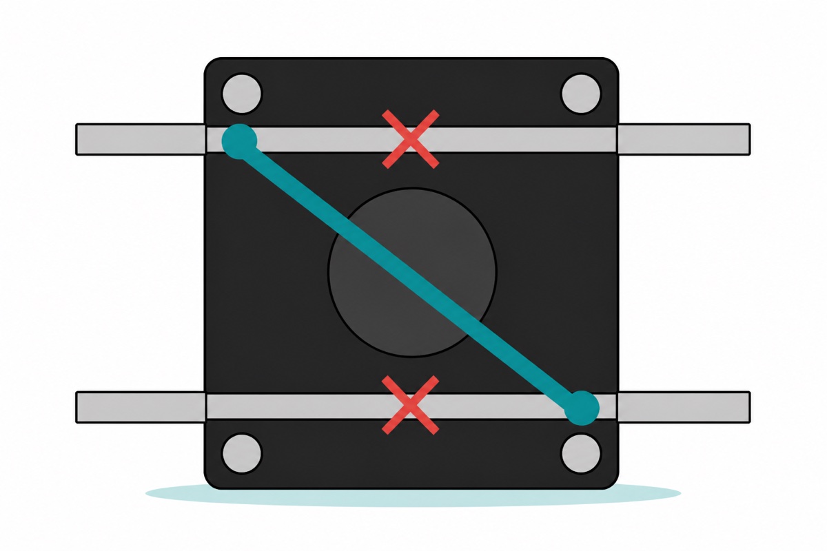
The 6×6 tactile switch has four legs but only two circuits. Its legs leave the body two per side, and each leg is joined inside the housing to the leg facing it across the body — pressed or not, that facing pair is one piece of metal. The plunger’s job is to bridge one facing pair to the other. Hokuriku, Omron and SCHURTER all print the same internal circuit for their 6×6 parts, and the same 6.5 mm across by 4.5 mm along hole pattern, so the joined pair is always the wide one.
So the pair to avoid is the pair that faces each other across the body. Wire those two and you have soldered a permanent short across your input: the pin sits at 0 V from power-up and the button reads pressed forever, which is the commonest “my button is stuck” ticket. Choose two legs that sit diagonally opposite and you are guaranteed one leg from each circuit, whichever way the switch was dropped into the board. Straddle the breadboard’s centre trench with it and the rule becomes something you can see: the two legs that share a numbered row are the joined pair, so take your two wires from different rows.
The same rule governs every four-leg miniature switch, the 12×12 capped button included: same two internal strips, same diagonal, just a bigger target on top. Its legs sit further apart than the 6×6’s, so line them up before you press and push straight down — rocking a tactile switch into a board splays the legs, and a bent leg is the only way to kill a part that has no electronics in it.
| From | To | Why |
|---|---|---|
| Uno GND | Breadboard blue negative rail | One ground feed the whole build shares |
| 6×6 tactile, one leg | Uno D2 | Raw button, so you can see the bounce |
| 6×6 tactile, the diagonally opposite leg | Blue negative rail | Pressing pulls D2 down to 0 V |
| 12×12 capped button, one leg | Uno D3 | The debounced button |
| 12×12 capped button, the diagonally opposite leg | Blue negative rail | Same two-wire pattern |
| LA38 e-stop, one NC screw terminal | Uno D4 | Closed while safe, so D4 sits LOW |
| LA38 e-stop, the other NC screw terminal | Blue negative rail | Any break in this pair reads HIGH |
All seven connections are plain male-to-male jumpers: the Uno’s headers are sockets, breadboard holes are sockets, and the LA38’s screw terminals clamp onto a bare male pin end — push the pin right under the clamp so the screw bites metal and not the plastic housing. Our jumper wire guide works the gender arithmetic through.
The single ground feed earns its jumper. An Uno R3 offers three GND sockets in total and this build already wants three grounds; take one wire from GND to the breadboard’s blue negative rail and every switch, sensor and module you add afterwards grounds to the rail instead of competing for the board. Parts only agree on what LOW means when they agree on where zero is, and that agreement is the ground rail.
How do you debounce a button so it actually works?
Every switch on this page, from the 6×6 tactile to the LA38, closes by pressing two springy pieces of metal together, so when they meet they bounce apart and back several times before settling. Jack Ganssle put eighteen switches on a scope and measured it: an average of 1,557 µs of bouncing and 6,200 µs at the worst across sixteen ordinary ones, with a bad specimen chattering for 157 ms. An Uno runs loop() tens of thousands of times a second, so it reads every bounce as a fresh press.
That is where the 40 ms below comes from rather than superstition: it swallows the 6.2 ms worst case six times over, and it still sits well under the roughly 100 ms at which a person begins to feel a button as laggy.
The tempting wrong fix is delay(50) inside loop(). It works on a sketch that does nothing else and poisons every project it touches: for those 50 ms the Arduino cannot read the second button, check the e-stop or refresh a display. Note the millisecond at which the level moved instead, and refuse to believe the new level until it has held still. millis() is counted by a hardware timer that runs whether your code is looking or not.
// Push buttons on an Arduino Uno: raw vs debounced, plus a fail-safe e-stop.
// Every switch simply shorts its pin to GND, so no external resistors.
//   D2  6x6 tactile, DIAGONAL legs: one to D2, one to the GND rail   (raw)
//   D3  12x12 tactile, DIAGONAL legs: one to D3, one to the GND rail (debounced)
//   D4  e-stop NC pair: one screw terminal to D4, one to the GND rail
//       GND rail = the breadboard's blue rail, fed once from an Uno GND pin
//   D13 the on-board LED stands in for the machine

const uint8_t PIN_RAW   = 2;
const uint8_t PIN_CLEAN = 3;
const uint8_t PIN_ESTOP = 4;

// Ganssle measured 6.2 ms of bounce worst case across 16 ordinary switches.
// 40 ms clears that with a wide margin and is still under the ~100 ms at
// which a person starts to feel a button as laggy.
const unsigned long DEBOUNCE_MS = 40;

unsigned long rawCount = 0, cleanCount = 0;
bool rawLast = HIGH;
bool cleanReading = HIGH;    // whatever the pin says right now
bool cleanAccepted = HIGH;   // the level we have agreed to believe
unsigned long cleanChangedAt = 0;
bool wasHalted = false;

void report() {
  Serial.print(F("raw "));
  Serial.print(rawCount);
  Serial.print(F("   debounced "));
  Serial.println(cleanCount);
}

void setup() {
  Serial.begin(9600);
  pinMode(PIN_RAW,   INPUT_PULLUP);
  pinMode(PIN_CLEAN, INPUT_PULLUP);
  pinMode(PIN_ESTOP, INPUT_PULLUP);
  pinMode(LED_BUILTIN, OUTPUT);
  Serial.println(F("Press each button once, then compare the two counts."));
}

void loop() {
  // --- The e-stop is read first, every pass. ---------------------------
  // The NC pair is closed while all is well, holding the pin at 0 V. Pushing
  // the mushroom head opens it - and so does a cut wire, a loose screw or an
  // unplugged lead. Every one of those reads HIGH, and every one of them
  // stops the load. That is what fail-safe means in practice.
  bool halted = (digitalRead(PIN_ESTOP) == HIGH);
  digitalWrite(LED_BUILTIN, halted ? LOW : HIGH);
  if (halted != wasHalted) {
    Serial.println(halted ? F("E-STOP OPEN - load off")
                          : F("E-stop closed - load on"));
    wasHalted = halted;
  }
  if (halted) return;   // nothing below runs while the chain is open

  // --- D2: believe the pin the instant it moves. -----------------------
  bool rawNow = digitalRead(PIN_RAW);
  if (rawLast == HIGH && rawNow == LOW) {   // pull-up beaten: contact closed
    rawCount++;
    report();
  }
  rawLast = rawNow;

  // --- D3: believe the pin only after it has held still. ---------------
  bool cleanNow = digitalRead(PIN_CLEAN);
  if (cleanNow != cleanReading) {    // the level moved: restart the clock
    cleanReading = cleanNow;
    cleanChangedAt = millis();
  }
  // millis() keeps counting on its own, so the rest of loop() is never
  // blocked while we wait - that is the whole difference from delay(40).
  if (millis() - cleanChangedAt >= DEBOUNCE_MS && cleanReading != cleanAccepted) {
    cleanAccepted = cleanReading;
    if (cleanAccepted == LOW) {
      cleanCount++;
      report();
    }
  }
}
It compiles to 2,722 bytes, 8% of the Uno’s flash. Open the Serial Monitor at 9600 baud, press each button ten times and read the counters: the debounced one says ten, the raw one says more. The gap is the bounce.
With the e-stop not yet wired, the sketch sits there announcing E-STOP OPEN and ignoring both buttons. That is not a broken sketch, it is the fail-safe reading an open circuit exactly as designed — and it is the fastest proof the logic works. Drop one jumper from D4 to the negative rail to stand in for a closed contact and the rest of the build comes to life.
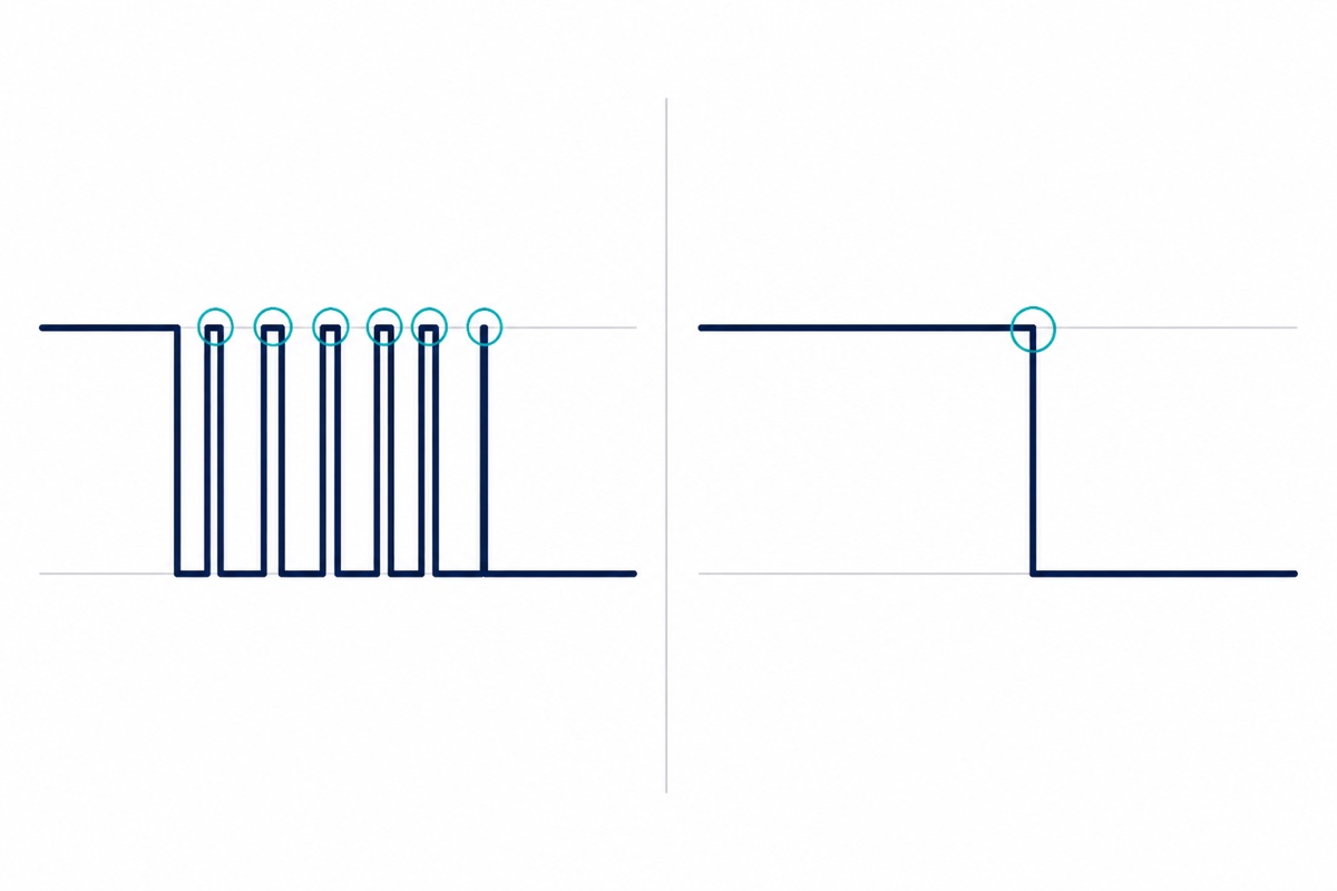
The chatter itself, on a scope:
How do you wire a panel-mount emergency stop button to an Arduino?
The LA38 emergency stop drops through a 22 mm panel hole, and its rear contact block presents one NO pair and one NC pair on screw terminals. Take the NC pair: one terminal to D4, the other to GND, D4 on INPUT_PULLUP. The closed contact holds D4 at 0 V while the head is out; strike it and the latch opens, the pull-up wins, D4 goes HIGH and the load stops. So does a severed wire.
Find that NC pair before you wire it. The block marks its function beside the screws, NC on the pair you want and NO on the other, and where the marking is worn or numbered rather than lettered the switch will tell you itself: put a multimeter on continuity across one pair, and the pair that beeps with the mushroom head out is the normally closed one. The Uno can answer it too — wire a pair to D4 and GND, upload the sketch above, and the pair that reports the load ON while nothing is pressed is NC. Guessing wrong here gives you exactly the NO-wired e-stop described above: perfect on the bench, silent when it matters.
Read this part before you fit one to anything that moves. An emergency stop on an Arduino input stops your code. It does not stop the motor, the heater or the spindle: those are still powered, and a crashed sketch or a driver latched on by its own logic keeps them running with the button pressed flat. A real machine e-stop breaks the actuator’s own supply, in the power path, where no software gets a vote — our relay safety guide covers that side. Wire the Arduino input as well, but never instead.
The LA38’s contact block also carries a mains-level rating, and that is not an invitation. Everything here is 5 V logic; mains wiring is work for a qualified electrician and out of scope. For switching a workshop machine’s own supply, an enclosed KAO-5M start/stop box is the right part — a power switch, not a GPIO part.
A hands-on look at the LA38 itself:
What are the four kinds of button terminal?
A button’s terminal is the bit your wire joins to, and it decides what tools the job needs.
| Terminal | What it looks like | How you join to it | Example |
|---|---|---|---|
| Through-hole legs | Bent silver legs, two per side | Push into a breadboard, or solder | 6×6 tactile |
| Solder lug | Flat metal tab with a hole in it | Hook the wire through and solder | R13-507 |
| Screw terminal | Silver screws under a clear cover | Clamp bare wire or a male pin end | LA38 e-stop |
| Module header pins | Three right-angle pins on a small PCB | Male-to-female jumpers, no soldering | Button sensor module |
Only the module is solder-free at both ends. Plan for the R13-507: its two solder lugs need an iron, some wire and a few minutes with our soldering guide. Its datasheet rates it at 6 A at 125 VAC and 3 A at 250 VAC through a 16 mm hole — far beyond anything a 5 V pin will ask of it.
That rating is what separates a signal switch from a power switch, and it swings hard across this page. The 12×12 capped button is rated for 0.1 A at 12 V DC, a sixtieth of the current the R13-507 will carry. Neither figure matters for the build above, because an INPUT_PULLUP pin pulls a quarter of a milliamp through the contact at most. It matters the moment you decide to run the LED strip, the pump or the fan through the button instead: undersized contacts arc, pit and eventually weld, and a welded contact is stuck ON — the worst way for anything with a motor in it to fail. Give the load a relay or a MOSFET and let the button only say when.
Common mistakes we see from real customers
Wiring a tactile switch across a facing pair of legs. The button reads pressed the moment the board powers up and nothing you change in code helps, because those two legs were already one piece of metal. Move one wire to the diagonally opposite leg.
Leaving the pin on plain INPUT. The reading wanders, the sketch fires by itself when a hand comes near, and it looks like a faulty switch. One word — INPUT_PULLUP — removes the whole class of fault.
Debouncing with delay(). The button behaves, and then the second button starts missing presses and the display stutters. The delay was never free; it just charged the rest of the sketch.
Taking the e-stop from the NO pair. It tests perfectly on the bench and fails silently in the field, because a broken wire and a button nobody pressed look identical to the controller. Move it to NC and the failure becomes a stop.
FAQ
Which pins of a 4-pin push button switch do I connect?
Any two that sit diagonally opposite each other. The two legs that face each other across the body are joined internally, so wiring those gives you a permanent short and a button that always reads pressed.
Do I need a resistor for an Arduino push button?
Not an external one. pinMode(pin, INPUT_PULLUP) enables a 20–50 kΩ resistor inside the ATmega328P that holds the pin at 5 V, so the switch only has to connect the pin to GND. Pressed then reads LOW.
What is the difference between a momentary and a latching push switch?
A momentary switch is closed only while you hold it. A latching one stays where you pushed it: the LA38 emergency stop locks down when struck and releases only when its mushroom head is twisted.
Why is a red emergency stop button wired normally closed?
So that failure stops the machine. The NC contact conducts while everything is fine, and pressing the button opens it. A cut wire, a loose screw or an unplugged lead opens it too, so every wiring fault produces a stop rather than a button that quietly no longer works.
How long should an Arduino button debounce be?
Around 40 ms for ordinary switches. Measured bounce on typical contacts peaks near 6 ms, so 40 ms leaves a wide margin while staying below the point where a person notices the delay. Time it with millis(), never with delay().
Last updated August 2026. Stuck? Chat with us on WhatsApp.

Pingback: Vibration Motor vs Vibration Sensor for Arduino