

Tutorials
Active vs Passive Buzzer with Arduino: Wiring, tone() and Alarms
Aug
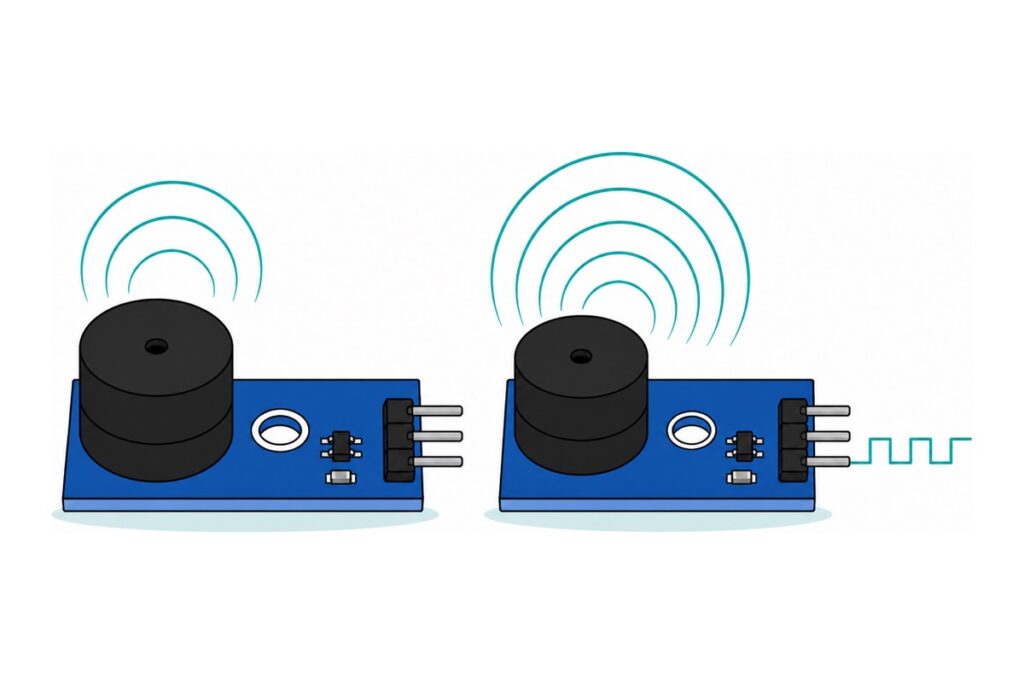
An active buzzer carries its own oscillator, so steady DC makes it hold one fixed note; a passive buzzer is a bare transducer that only makes the waveform you feed it. Give each one a steady voltage and the difference is instant — the active one sings, the passive one clicks once and goes quiet.
What actually differs inside an active and a passive buzzer?
The Active Buzzer Module has a self-driving oscillator potted under its black can beside the coil and diaphragm. Apply DC and that circuit generates its own alternating drive at the element’s resonant peak, about 2.3 kHz, where a 12 mm can is loudest. You get one note, and your pin decides only whether it is on.
The Passive Buzzer Module has no oscillator — just the coil and diaphragm. The diaphragm moves once for every edge you send it, so the pitch is nothing but the frequency of your square wave. Steady DC pulls the diaphragm to one position and holds it there: a single click, then silence.
That is the entire trade. Active costs you one digitalWrite() and gives one tone; passive costs you a hardware timer and gives you a scale.
Parts list — tell the two buzzers apart, then build the alarm
 Arduino Uno Compatible SMD UNO R3 with Type B Cable - ATMEGA328P with CH340G-Microcontroller Project
 Buzzer Active Passive Buzzer 5V Electronic Sound Alarm Module Tone Piezo - Active Buzzer Module
 Buzzer Active Passive Buzzer 5V Electronic Sound Alarm Module Tone Piezo - Passive Buzzer Module
 Tilt Sensor Vibration Sensor Tilt Switch Module Alarm Trigger SW1801P For Arduino Application - VIBRATION/ TILT SENSOR
 40pcs Dupont Wire 10cm 20cm 30cm for Breadboard DIY Experiment Jumper Wire Breadboard wire - DUPONT WIRE M-F 20CM
Louder option
| Item | Price | Qty | |
|---|---|---|---|
 SFM-20B Active Buzzer DC 3-24V Piezoelectric Long Continous BeepSFM208S SFM-20B Active Buzzer DC 3-24V Piezoelectric Long Continous BeepSFM208S | RM3.15 |
A 3–24 V active buzzer on flying leads for when a module is not loud enough. It draws at most 12 mA at its rated 12 V, so an Uno pin drives it directly at 5 V — but its tinned stranded ends fit no header, so twist them onto jumper tips or land them in a screw terminal.
The bare passive buzzer is the same element on two stiff breadboard-pitch pins — pennies, but those pins need a breadboard, not a jumper socket. The KY-006 passive module is a budget board with straight pins, rated 1.5–2.5 kHz.
How do you tell them apart when they look identical?
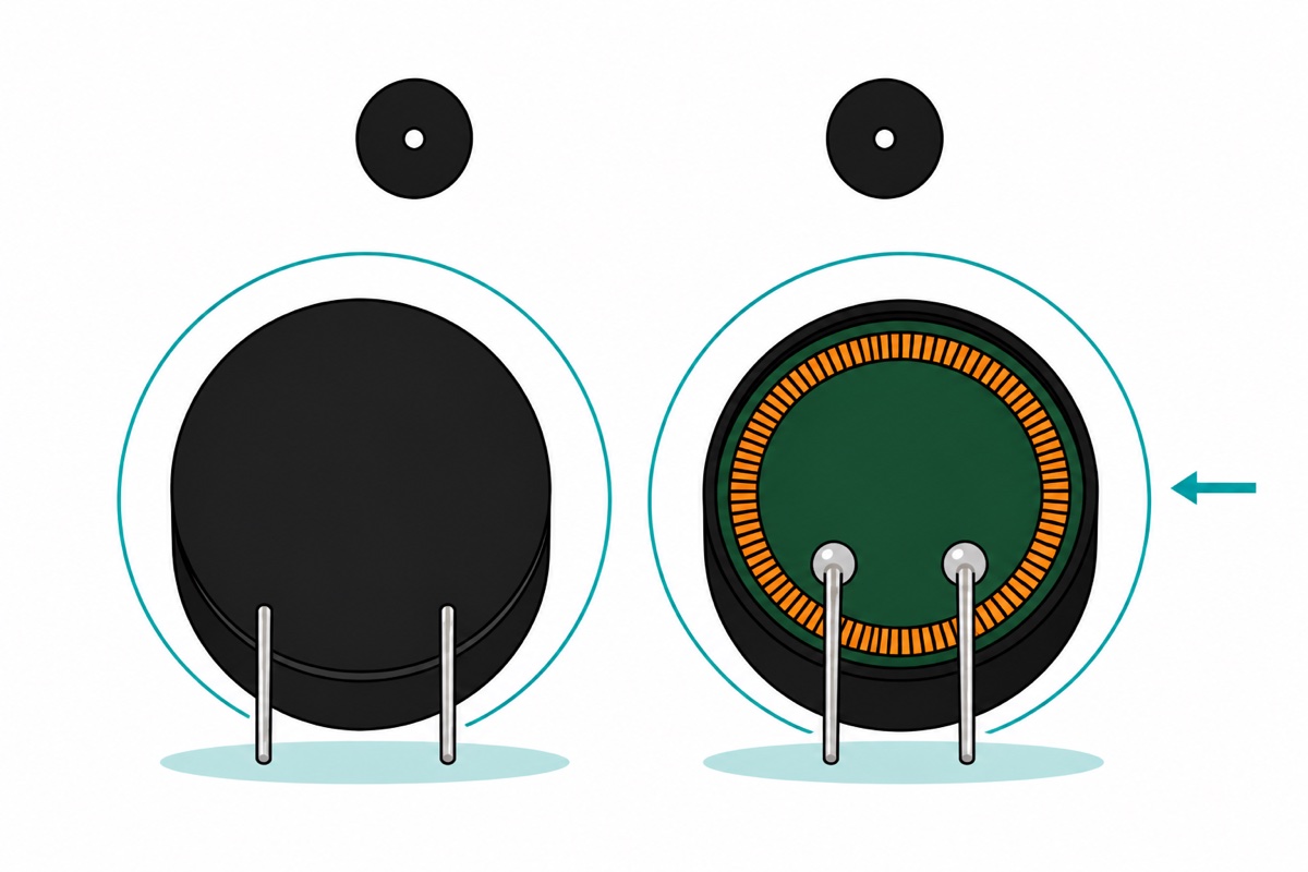
Our Active Buzzer Module and Passive Buzzer Module are deliberate twins: same blue PCB, same MH-FMD marking, same three pins labelled GND, I/O and VCC. Bare buzzers are worse — from above they are the same black disc with a centre hole. Two tells settle it.
The code test is definitive. Wire the module’s VCC to 5 V, GND to GND and I/O to D8, then hold that pin steady and listen: a continuous tone means active, one faint click means passive. Four lines.
const uint8_t IO_PIN = 8;

void setup() {
  digitalWrite(IO_PIN, HIGH);   // silent first - see the wiring section
  pinMode(IO_PIN, OUTPUT);
  delay(1000);
  digitalWrite(IO_PIN, LOW);    // steady DC from here on
}
void loop() {}
A bare buzzer reverses that sketch, because nothing sits between the pin and the element: (+) leg to the pin, the other leg to GND, and drive the pin HIGH to sound it. Put a 100 Ω resistor in the path and keep the test brief — a bare buzzer takes its whole current straight from the pin instead of from a transistor, and a passive element is only a coil of a few tens of ohms, far less than an Arduino pin should ever be asked to drive on its own.
The underside needs no power. Turn a bare buzzer over: an active one is sealed flat with black potting compound, because there is a driver circuit under there to protect, while a passive one shows its drive coil and two solder points in plain sight. Height is a weaker hint — the active can is slightly taller — and it only helps when you hold both. Label the bag the day it arrives.
Worth hearing them side by side:
How do you wire the buzzer modules to the Uno?
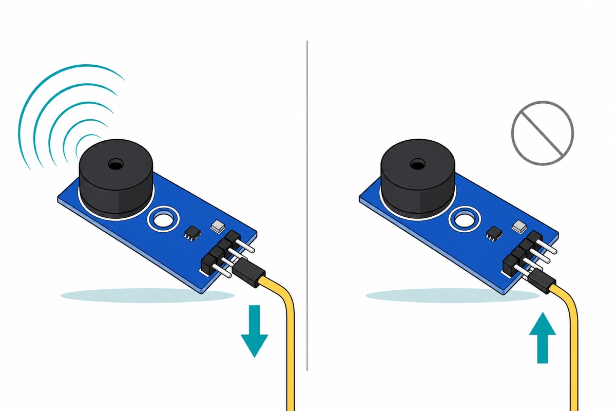
The buzzer modules carry three right-angle male pins and the SW-18010P vibration module four straight male pins, while the Uno’s headers are female sockets — so one pack of male-to-female jumpers wires the whole build. No breadboard, nothing to solder. Read the silkscreen before you push the connectors on: both buzzer modules run GND, I/O, VCC along the header, supply and ground at opposite ends, so a three-way connector fitted back to front lands 5 V on the module’s ground pin.
| Module pin | Uno pin | Why |
|---|---|---|
| Buzzer VCC (both modules) | 5V | Supplies the buzzer element through the module’s transistor |
| Buzzer GND (both modules) | GND | Return path for the buzzer current and the signal |
| Active buzzer I/O | D8 | Any ordinary digital pin; it only ever goes high or low |
| Passive buzzer I/O | D9 | Any digital pin — tone() works on all of them |
| Sensor VCC | 5V | Powers the LM393 comparator and both indicator LEDs |
| Sensor GND | GND | Third pin, not the last one — the silkscreen order is AO DO GND VCC |
| Sensor DO | D2 | D2 is interrupt INT0 — an Uno has external interrupts on D2 and D3 only |
| Sensor AO | not used | Raw switch voltage; the digital output is what we want |
One thing no parts list shows: the Uno has three GND sockets but only one 5 V socket, and a single jumper end fills it. The alarm at the end of this article runs the buzzer and the sensor at once, so it needs a second 5 V feed — take it from the 2×3 ICSP block near the board’s edge, a male header whose 5 V pin sits beside the marked pin 1 in the other row, so a female jumper end pushes straight onto it. A mini breadboard shares the rail just as well.
Why does the buzzer scream the moment your sketch runs?
Both MakerHub buzzer modules are silkscreened 低电平触发 — low-level trigger, and it describes the circuit exactly. The SOT-23 part beside the lettering is an S8550 PNP transistor with its emitter on VCC, and the resistor next to it is marked 102, which in the three-digit code is 10 × 10², or 1 kΩ. That resistor connects the base to the I/O pin.
A PNP transistor conducts when its base is pulled below its emitter. Pull I/O to 0 V and the base sits a full supply below VCC; roughly (5 V − 0.7 V) ÷ 1 kΩ ≈ 4 mA flows out of the base, which saturates the transistor and connects the buzzer to 5 V. Hold I/O at 5 V and there is no emitter-base voltage at all, no base current, and the buzzer is dead. So LOW is the sound state and HIGH is silence. That 4 mA is sunk by the Arduino pin, comfortably inside the 20 mA per I/O pin the Uno is specified for.
The same arithmetic settles what a 3.3 V board can do with these modules. Drive I/O from an ESP32 while the module still runs on 5 V and a HIGH of 3.3 V sits 1.7 V below the emitter, so about (5 V − 3.3 V − 0.7 V) ÷ 1 kΩ ≈ 1 mA keeps leaving the base: the transistor never switches off and the buzzer never stops. Power the module’s VCC from the 3.3 V rail instead and the levels match again — at HIGH there is no emitter-base voltage at all, and the buzzer is properly silent. It plays a little softer on the lower rail, and that is the whole cost of the fix.
Now the trap. On an AVR, pinMode(pin, OUTPUT) switches on the pin driver while the output latch still holds its reset value of zero — so the pin goes low the instant it becomes an output, which on these modules is the sound state. Before that it was a floating input and the buzzer was silent, which is exactly why the noise starts the moment your sketch reaches setup(). The fix is one line, in this order:
digitalWrite(BUZZER_PIN, HIGH);   // set the latch while still an input
pinMode(BUZZER_PIN, OUTPUT);      // pin comes up HIGH, never passes through LOW
The same trap has a second form in noTone(): the Arduino AVR core ends that function with digitalWrite(_pin, 0), and a duration-limited tone() finishes the same way — on an Uno the note’s own timer interrupt calls noTone() when the duration runs out. On a high-level-trigger buzzer that is silence; on ours it is a permanent siren. Follow every noTone() with digitalWrite(pin, HIGH).
How do you play a melody with tone()?
The tone() function hands your pin to a hardware timer that toggles it at twice the frequency you asked for, then returns immediately — the note keeps playing while your code carries on. The inverting transistor does not spoil this: a 50% square wave turned upside down is still a 50% square wave at the same frequency, so the module plays exactly the pitch you asked for.
That one timer sets the limits. On an Uno tone() claims Timer2, so PWM on pins 3 and 11 stops while a note plays, and only one note sounds at a time. Notes far from the element’s resonant peak also come out quieter — that is the diaphragm, not your code.
// Eight-note scale on the PASSIVE buzzer module. Uno, I/O on D9.
const uint8_t IO_PIN = 9;
const uint8_t BUZZER_OFF = HIGH;   // low-level trigger: HIGH is silent

const int NOTES[] = { 262, 294, 330, 349, 392, 440, 494, 523 };  // C4..C5
const uint8_t NOTE_COUNT = sizeof(NOTES) / sizeof(NOTES[0]);
const int NOTE_MS = 250;
const int GAP_MS  = 60;

// noTone() ends by writing the pin LOW, and on a low-level-trigger
// module LOW means "sound". Always park the pin HIGH afterwards.
void silence() {
  noTone(IO_PIN);
  digitalWrite(IO_PIN, BUZZER_OFF);
}

void setup() {
  digitalWrite(IO_PIN, BUZZER_OFF);   // silent before the pin becomes an output
  pinMode(IO_PIN, OUTPUT);
}

void loop() {
  for (uint8_t i = 0; i < NOTE_COUNT; i++) {
    tone(IO_PIN, NOTES[i]);   // square wave at this frequency, hands off
    delay(NOTE_MS);           // the note keeps sounding while we wait
    silence();
    delay(GAP_MS);
  }
  delay(2000);
}
That compiles to 2,390 bytes, 7% of the Uno’s flash. Drop silence() and the scale runs together into one unbroken howl.
How do you build an alarm that only sounds when it should?
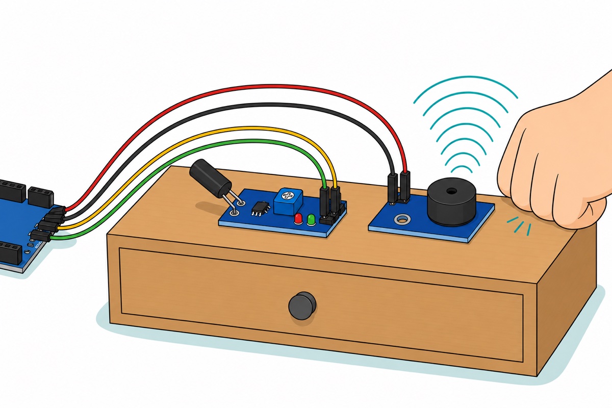
The SW-18010P inside that black can is a coil spring wrapped around a centre pin, normally open. A shock throws the spring against the pin for a few milliseconds and it springs back — so this is an event sensor, and one knock produces a burst of contacts as the spring rattles.
The LM393 turns that mess into clean digital edges. A resistor holds the switch node up near VCC, closing the spring drags it to ground, and the comparator reports which side of a reference voltage the node is on — the blue 3362 trimmer is that reference. By design DO rests high and pulses low. Wind the trimmer to either end of its travel, though, and the reference lands outside the range the node ever reaches, so DO sits stuck, no edge ever reaches D2, and the alarm never fires at all. Set it once: power the board, leave it still, turn the trimmer until the DO-LED has just gone out, then tap the bench and watch it flash. If you would rather read a number than a light, print digitalRead(2) in a bare loop: it should show 1 while the board sits still and 0 on a knock. That reading is also what confirms the interrupt below belongs on FALLING.
The sketch then does four things, each answering a way alarms annoy people. It ignores everything for ten seconds after power-up, so setting it down is not an event. It ignores repeat edges within 40 ms, because that is one knock rattling rather than four. It needs four separated knocks inside 1.5 seconds, so a passing lorry is not enough. And it latches the siren for five seconds on millis() rather than delay() — a delay() siren is deaf for its whole duration, which matters the moment you want a button that silences it.
// Vibration alarm. SW-18010P DO -> D2, ACTIVE buzzer I/O -> D8. Uno.
const uint8_t SHAKE_PIN  = 2;   // D2 is INT0 - the only reason this pin is used
const uint8_t BUZZER_PIN = 8;
const uint8_t BUZZER_ON  = LOW;    // low-level trigger module
const uint8_t BUZZER_OFF = HIGH;

const unsigned long ARM_DELAY_MS  = 10000UL; // time to set it down and walk off
const unsigned long BOUNCE_MS     = 40UL;    // one knock rattles the spring
const unsigned long WINDOW_MS     = 1500UL;  // knocks must land inside this
const uint8_t       PULSES_NEEDED = 4;       // lower = jumpier alarm
const unsigned long SIREN_MS      = 5000UL;

volatile unsigned long lastEdgeMs = 0;
volatile unsigned int  pulses     = 0;

bool armed = false, sounding = false, windowOpen = false;
unsigned long windowStart = 0, sirenStart = 0;

// Runs the instant DO falls, whatever loop() is doing. Counting only -
// the decisions live in loop() where they are easy to read.
void onShake() {
  unsigned long now = millis();
  if (now - lastEdgeMs < BOUNCE_MS) return;   // still the same knock rattling
  lastEdgeMs = now;
  pulses++;
}

// pulses is 16-bit, so the AVR reads it in two instructions. Block
// interrupts across the read or an edge can land between the halves.
unsigned int readPulses() {
  noInterrupts();
  unsigned int n = pulses;
  interrupts();
  return n;
}

void clearPulses() {
  noInterrupts();
  pulses = 0;
  interrupts();
}

void setup() {
  digitalWrite(BUZZER_PIN, BUZZER_OFF);   // BEFORE pinMode - never pass through LOW
  pinMode(BUZZER_PIN, OUTPUT);

  // The LM393's output is open-collector: it can pull the line down but
  // never push it up, so give it a pull-up to fall away from.
  pinMode(SHAKE_PIN, INPUT_PULLUP);
  attachInterrupt(digitalPinToInterrupt(SHAKE_PIN), onShake, FALLING);
}

void loop() {
  unsigned long now = millis();

  // 1. Arming delay - ignore your own handling while you leave the room.
  if (!armed) {
    if (now >= ARM_DELAY_MS) { clearPulses(); armed = true; }
    return;
  }

  // 2. Siren already running: let it finish, then re-arm quietly.
  if (sounding) {
    if (now - sirenStart >= SIREN_MS) {
      digitalWrite(BUZZER_PIN, BUZZER_OFF);
      sounding = false;
      windowOpen = false;
      clearPulses();          // knocks during the siren do not retrigger it
    }
    return;
  }

  unsigned int n = readPulses();
  if (n == 0) return;

  // 3. The first knock opens a window.
  if (!windowOpen) { windowOpen = true; windowStart = now; }

  // 4. Enough knocks inside that window - this is real.
  if (n >= PULSES_NEEDED) {
    digitalWrite(BUZZER_PIN, BUZZER_ON);
    sounding = true;
    sirenStart = now;
    return;
  }

  // 5. Window expired without enough knocks - a passing lorry. Forget it.
  if (now - windowStart >= WINDOW_MS) {
    windowOpen = false;
    clearPulses();
  }
}
Mount the sensor on the thing you are protecting rather than beside it — the spring answers the shock that actually reaches it. Then tune with the constants at the top: if one sharp tap already fires the alarm, the spring is still ringing past 40 ms, so raise BOUNCE_MS; if a real shove never reaches four counts, lower PULSES_NEEDED or widen WINDOW_MS.
It compiles to 1,370 bytes and 30 bytes of RAM, leaving room for a keypad, a display or a silence button. Keep it all on the Uno’s 5 V rail — nothing here belongs near mains. If you fit the louder SFM-20B, bench-test it at arm’s length rather than beside your ear; it is built to be heard across a house. It also inverts the sketch, being a bare two-wire buzzer with no transistor in front of it: red lead to D8, black to GND, and swap the constants so BUZZER_ON is HIGH and BUZZER_OFF is LOW. Leave them as they are and the siren runs backwards, quiet only while the alarm is triggered.
Swap the spring for a PIR and you have our motion-triggered build, which fires on a person crossing a room rather than on furniture being moved; swap it for a gas or flame sensor and you have the MQ-2 smoke alarm or the flame alarm. An IR remote makes a tidy silence button, since millis() timing leaves the loop free to watch for it.
Common mistakes we see from real customers
Buying an active buzzer to play a tune. The commonest pattern: tone() runs, the frequencies change in the code, every note sounds identical. Nothing is broken — the internal oscillator sets the pitch, so your square wave only decides on or off.
Counting the sensor header from the wrong end. Habit says the ground pin sits at the end of the row. Here VCC is last and GND is third — the order is AO DO GND VCC — so a header read backwards puts 5 V into the analog output and leaves the board unpowered.
Treating a floating pin as “off”. A pin left as an input is silent on these modules, which hides the problem until something else in the sketch drives it low. Set the level explicitly in setup() and the buzzer’s state is never an accident.
Blaming the buzzer for a stuck trimmer. An alarm that never reacts to a knock is usually the vibration module’s reference wound past the end of the switch node’s range, not a faulty buzzer — DO stops moving at all, so the sketch never sees an edge.
FAQ
Can I use tone() with an active buzzer?
You can call it, but the pitch will not change. The active buzzer’s oscillator is fixed, so any frequency you pass simply switches it on. Use it for beeps and alerts; use a passive buzzer for anything with a tune.
My buzzer beeps non-stop as soon as the Arduino powers up — what is wrong?
Almost certainly nothing. Both our modules are low-level trigger, so a pin sitting at 0 V means “sound”. pinMode(pin, OUTPUT) alone leaves the pin low, so write it HIGH first, then set it as an output.
Which buzzer should I choose for a school alarm project?
The active module, unless the marking scheme asks for a tune. One line of code, loud for its size, no timer to explain. Keep a passive module in the box for the project that wants a melody.
Do these modules need a resistor or a transistor?
No — the transistor is already on the board, which is the point of the module. The Arduino pin only handles about 4 mA of base current.
How do I make the alarm louder?
Move to the SFM-20B, a bigger element built for continuous alarm duty. It runs from 3 to 24 V and draws at most 12 mA at its rated 12 V, so an Uno pin drives it directly at 5 V — and it gets louder as you raise its supply. It has no transistor in front of it, so it sounds on HIGH: swap BUZZER_ON and BUZZER_OFF when you fit it.
Active for “something happened”, passive for anything that carries a tune — and on both, HIGH is how you ask for quiet.
Last updated August 2026. Stuck? Chat with us on WhatsApp.

Pingback: 3 Primary School Science Projects: No Code, No Solder