

Tutorials
NEO-6M GPS Arduino Code and Wiring: Getting a First Fix
Aug
A NEO-6M gives an Arduino live coordinates over three wires — VCC to 5 V, GND to GND, and the module’s TX crossed to a SoftwareSerial pin at 9600 baud — but only outdoors. Indoors it still powers up, still sends data, and still never fixes, and its fix LED simply never blinks. That is a working module, not a dead one.
What do you need to read GPS coordinates on an Arduino?
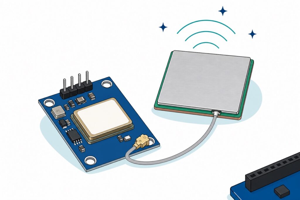
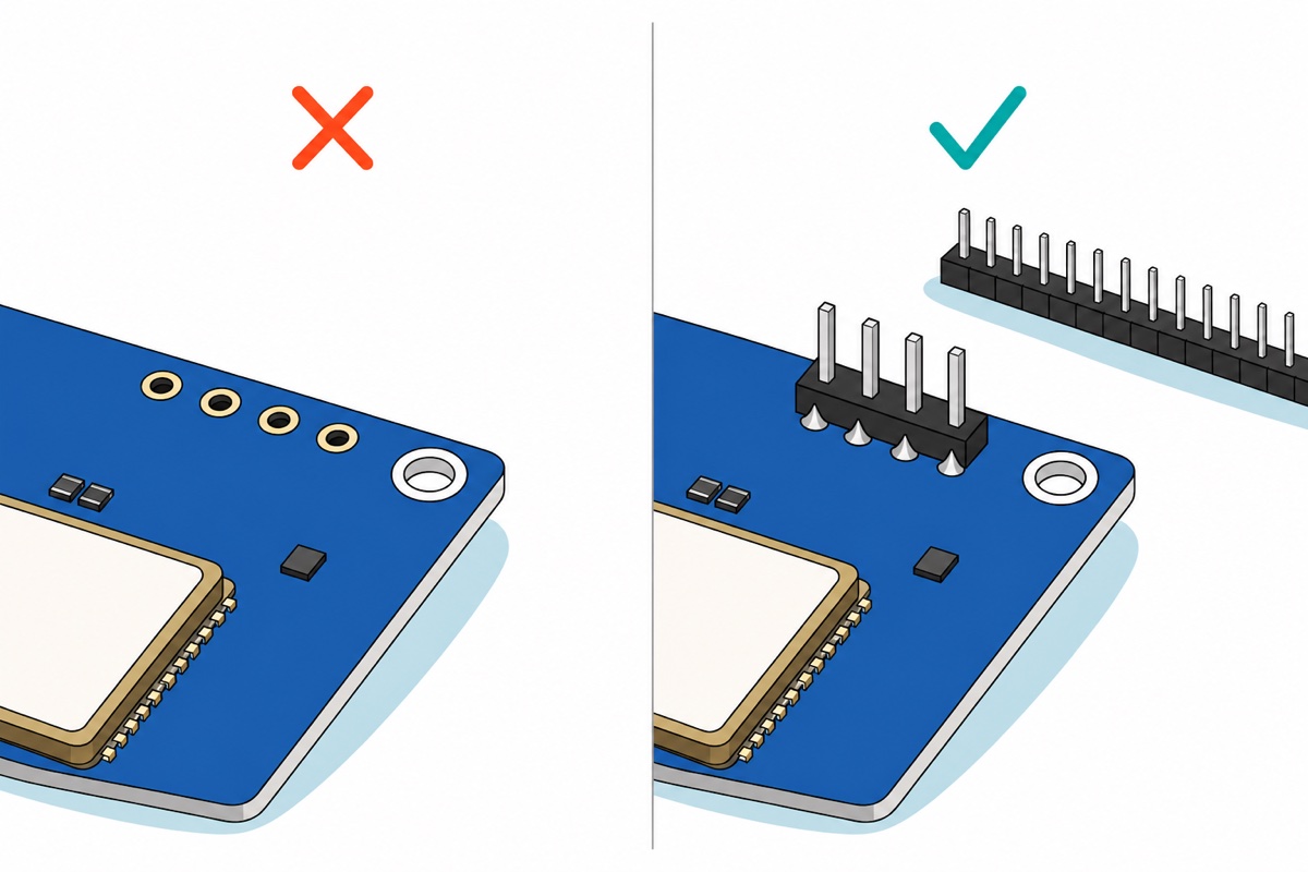
The GY-NEO-6M GPS module is a blue board carrying a silver-canned u-blox NEO-6M receiver, with a square 25 mm silver-shielded ceramic patch antenna on a grey coaxial pigtail. Its four connections are silkscreened VCC, RX, TX, GND along the top edge — and they arrive as bare plated holes. Four pins snapped off a 40-pin male header strip and soldered in is the first step of this build, before any wiring; our header-pin soldering guide covers the technique.
Parts list — NEO-6M GPS module with an Arduino Uno, coordinates on the Serial Monitor
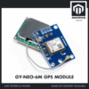 GPS Module GY NEO 6M/8M with Ceramic Antenna Time and Location Tracking - For Arduino IOT Project - GY-NEO-6M GPS MODULE
 Arduino Uno Compatible SMD UNO R3 with Type B Cable - ATMEGA328P with CH340G-Microcontroller Project
 2.54mm Pin Header Female Male Single Row Header 40P Connector Black White Red Yellow Green Blue - 40P MALE HEADER (BLACK)
 40pcs Dupont Wire 10cm 20cm 30cm for Breadboard DIY Experiment Jumper Wire Breadboard wire - DUPONT WIRE M-F 20CM
Optional — bench readout, cable and soldering kit
 0.96‘ OLED Display Module Blue White Screen I2C IIC Serial 128X64 LCD Display Board - 0.96' OLED WHITE
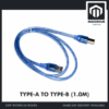 Data Cable Type-A Type-C MicroUSB Type-B 0.5m 1m 30cm 0.3m 100cm Data Transfer Upload Code - TYPE-A TO TYPE-B (1.0M)
 80W Electronics Soldering Iron with LCD Display Ajustable Temperature Microconstroller Electronic Project
 50g Soldering Wire Lead with Flux Core 1mm Diameter
The 0.96-inch OLED turns this into a handheld that shows coordinates without a laptop, and uses the Uno's I2C pins A4 and A5, which this build leaves free. The USB A-to-B cable is the square-plug lead the Uno's full-size socket takes — add one if that shape is not already in your drawer. The iron and solder are for the module's four header pins; skip them if you already own an iron.
Once soldered, the module wears male pins, the Uno has female shield sockets and the OLED ships with male pins fitted — so one pack of male-to-female jumpers wires both straight to the board, with no breadboard in the middle.
Why does the first GPS fix take minutes when the datasheet says 27 seconds?
The NEO-6M’s u-blox datasheet quotes a 27 second cold start, a 1 second hot start and 2.5 m horizontal accuracy, all under open sky. The gap between that and the ten minutes people actually wait is not a defective module; it is what the satellites are physically able to send.
Every GPS satellite transmits its navigation message at 50 bits per second, built from 30-second frames, and what a receiver needs from each satellite — its clock correction in subframe 1, its orbit data or ephemeris in subframes 2 and 3 — fills the first three of the five six-second subframes, so it repeats once every 30 seconds. A receiver that knows nothing must decode those 18 seconds of broadcast from every satellite it wants to use, and it only catches them from the start once per frame. Eighteen to thirty seconds of pure listening is the floor; no wiring change or library gets under it.
The rest of the message is the almanac, the coarse orbits of the whole constellation, spread thinly across 25 consecutive frames — 25 × 30 s = 12.5 minutes to receive in full. That is the number behind “leave it outside for a while”: u-blox puts a complete almanac at typically 12 minutes after the first fix. Once the module has it, it knows roughly where every satellite should be and stops searching blind.
That is also what the backup cell on the underside of the board is for. It holds the receiver’s clock and last ephemeris in battery-backed memory on about 22 µA, so the next power-up is a hot start — the module already knows the time and where to look, and the datasheet’s 1 second becomes realistic. Left unpowered for weeks, or with a flat cell, it is back to a cold start.
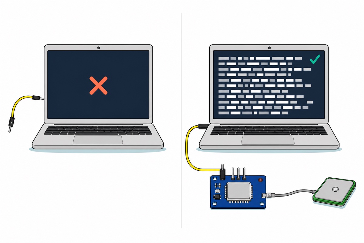
Watching one acquire outdoors makes the wait concrete:
Why does a NEO-6M never fix indoors?
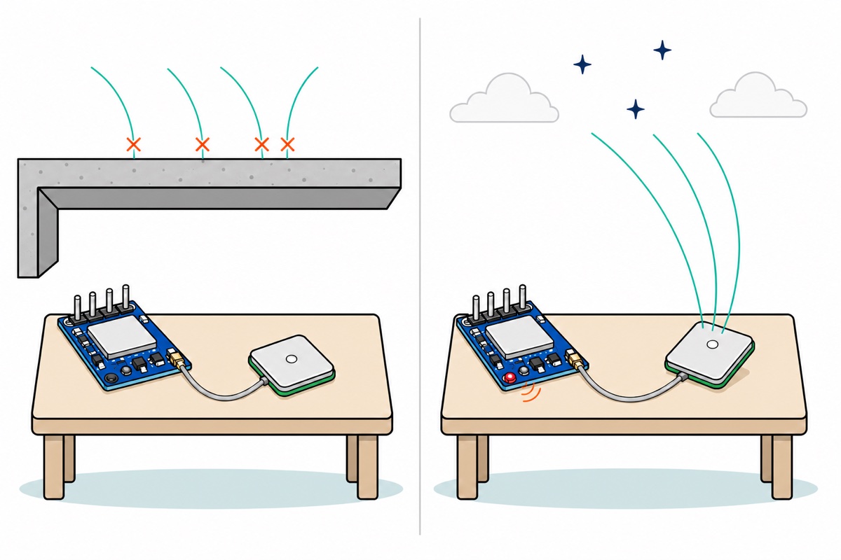
The NEO-6M’s sensitivity figures answer this exactly. Tracking and navigation are specified at −161 dBm, but cold start without aiding needs −147 dBm. Acquiring a satellite from scratch takes 14 dB more signal than keeping one you already have — a factor of twenty-five in power. The datasheet’s timings assume satellites arriving at about −130 dBm, which leaves a cold start only 17 dB of headroom where tracking has 31 dB — and ordinary concrete, tile and plaster eat that budget fast. So the module that appears to work fine on a windowsill after you carried it in from the garden will never get its first fix there.
The ceramic patch antenna is directional: the plain silver metal face is the receiving side, and it wants that face turned up at open sky, not stood on edge — u-blox’s antenna note asks for the patch plane parallel to the horizon with a full view of the sky. A balcony rail, a garden table or a car roof all work, and a flat metal surface underneath helps rather than hurts: it extends the antenna’s ground plane, which is why u-blox calls a car roof or dashboard the ideal spot and puts the useful ground-plane size at 50–70 mm square. What blocks the sky is metal above or beside that silver face, a car’s metallised tint film included, not metal under it. Rain and cloud do not: GPS at 1.5 GHz passes through droplets, while wet foliage and concrete absorb it.
How do you wire a NEO-6M to an Arduino Uno?
The NEO-6M chip runs on a 2.7–3.6 V rail, which the small regulator on the blue board makes from whatever you feed VCC, so 5 V in is correct and expected. The chip’s own I/O pins are the 3.3 V part: u-blox specifies their input range as 0 V to VCC and their absolute maximum as 3.6 V, so the Uno’s 5 V TX must not land directly on the module’s RX pin. The build below simply never uses that direction.
| Module pin | Uno | Why |
|---|---|---|
VCC |
5V |
The board’s regulator drops it to the receiver’s 3.3 V rail |
GND |
GND |
Shared reference — without it the serial line has no meaning |
TX |
D4 |
Crossed. The module talks, the Uno listens. This is the only wire the sketch needs |
RX |
— (leave empty) | Only needed to reconfigure the module. Uno TX is 5 V and needs a divider first |
TX to TX fails silently — two transmitters shouting at each other produce no data and no error message — which is why it is the mistake that survives longest. D4 itself is a free choice — any digital pin but 0 and 1.
The module’s TX drives its line to that internal 3.3 V rail. An ATmega328P at 5 V counts anything above 0.6 × VCC — 3.0 V — as a logic high, so 3.3 V clears the threshold with roughly 0.3 V of margin. That 0.3 V margin is thin, so noise on a long jumper can drag a bit below the threshold mid-character: keep the TX wire short. Our HC-05 Bluetooth guide uses the same receive-only pattern for the same reason.
Which library does NEO-6M Arduino code need?
The NEO-6M sends plain NMEA text at 9600 baud, 8-N-1, from the moment it powers up — GGA, GLL, GSA, GSV, RMC, VTG and TXT sentences, whether or not it has a fix. TinyGPSPlus by Mikal Hart, installed from Library Manager, turns those comma-separated sentences into numbers: raw latitude arrives as ddmm.mmmm, not decimal degrees, and each sentence carries a checksum to verify.
Those sentences also announce the fix state in plain text, which is a better health check than the LED. In $GPRMC the field just after the time is one letter — V for void, meaning no position yet, turning to A for active at the first fix — and $GPGGA says the same thing with a fix-quality digit, 0 before and 1 after. A module with no fix still sends both every second, position fields left empty.
/*
  NEO-6M GPS -> Arduino Uno: live coordinates on the Serial Monitor.
  Library: TinyGPSPlus by Mikal Hart (Library Manager).

  Wiring is RECEIVE-ONLY and TX/RX must CROSS:
    GPS VCC -> Uno 5V     GPS GND -> Uno GND     GPS TX -> Uno D4
  Uno D3 -> GPS RX is optional and needs a divider (see the article).

  Serial Monitor runs at 115200, the module at 9600. Two numbers on purpose.
*/
#include <SoftwareSerial.h>
#include <TinyGPS++.h>

const uint8_t  UNO_RX_PIN = 4;      // Uno LISTENS here  <- module TX
const uint8_t  UNO_TX_PIN = 3;      // Uno TALKS here    -> module RX (optional)
const uint32_t GPS_BAUD   = 9600;   // NEO-6M factory default, 8-N-1

SoftwareSerial gpsSerial(UNO_RX_PIN, UNO_TX_PIN);
TinyGPSPlus gps;

uint32_t lastReport = 0;

void setup() {
  Serial.begin(115200);
  gpsSerial.begin(GPS_BAUD);
  Serial.println(F("NEO-6M starting. Give it sky - indoors it will never fix."));
}

void loop() {
  // Drain the module every pass. Miss this and the 64-byte buffer overruns.
  while (gpsSerial.available() > 0) {
    gps.encode(gpsSerial.read());
  }

  if (millis() - lastReport < 2000) return;
  lastReport = millis();

  // FAULT 1: nothing arriving at all -> wiring or baud, never the sky.
  if (gps.charsProcessed() < 10) {
    Serial.println(F("NO DATA on D4 - check GPS TX -> D4 (crossed) and 9600 baud"));
    return;
  }

  Serial.print(F("chars "));
  Serial.print(gps.charsProcessed());
  Serial.print(F("  bad-checksum "));
  Serial.print(gps.failedChecksum());
  Serial.print(F("  sats "));
  if (gps.satellites.isValid()) {
    Serial.print(gps.satellites.value());
  } else {
    Serial.print(F("--"));
  }

  // FAULT 2: sentences flowing but no position -> antenna and sky, not wiring.
  if (!gps.location.isValid()) {
    Serial.println(F("  NO FIX YET - data is flowing, so the module is alive"));
    return;
  }

  Serial.print(F("  lat "));
  Serial.print(gps.location.lat(), 6);
  Serial.print(F("  lng "));
  Serial.print(gps.location.lng(), 6);
  Serial.print(F("  age "));
  Serial.print(gps.location.age());
  Serial.print(F(" ms  alt "));
  Serial.print(gps.altitude.meters(), 1);
  Serial.println(F(" m"));
}
On an Uno this compiles to 8,434 bytes of flash — 26% of the 32 KB — and 518 bytes of static RAM. The baud split earns its keep: SoftwareSerial holds only 64 received bytes, while the module delivers up to 960 bytes a second at 9600 baud. Printing a 110-character report at 9600 would occupy the board for about 115 ms, during which roughly 110 more bytes arrive and the buffer overflows; at 115200 the same line takes about 10 ms and under a dozen bytes queue up. Paste the printed latitude and longitude straight into Google Maps to check them.
Adding the OLED is four more wires — GND, VCC, SCL to A5, SDA to A4, noting that GND comes first on its header, not VCC — then Adafruit_SSD1306 at address 0x3C printing the same gps.location.lat() value. It is not free on an Uno: that library keeps a whole 128 × 64 frame buffer in RAM, 1 KB of the ATmega328P’s 2 KB, so wrap literal strings in F() and redraw sparingly — a full frame over I2C takes tens of milliseconds, and the 64-byte serial buffer fills in sixty-seven of them. Logging to an SD card instead is the natural next build — a GPS track is just timestamped rows, and our Arduino SD data logger handles the file side.
What does a healthy NEO-6M with no fix look like?
The NEO-6M gives two independent health signals, and reading them apart turns a dead-module panic into a two-minute diagnosis. The fix LED is driven by the TIMEPULSE output, which u-blox’s protocol specification defaults to one 100 ms pulse per second on GPS time, and to no pulse at all when there is no fix — and the receiver cannot align anything to GPS time until it has solved for its own clock offset, which requires a fix. So the LED is not a power light: dark or steady is the normal no-fix state, and a 1 Hz blink announces that coordinates are valid.
| What you see | What it means | Where to look |
|---|---|---|
| Nothing at all on the Serial Monitor | The module is not reaching the Uno | TX/RX crossed? Module TX on the pin the sketch declares? Monitor at 115200, gpsSerial at 9600? VCC and GND both connected? |
| Sentences flowing, no coordinates, LED dark | A perfectly healthy module with no sky | Go outdoors and wait — take the laptop with you, or fit the OLED so it reads without one. Check the antenna pigtail is clicked in, and watch $GPRMC for its V to turn A |
| Satellite count rising, still no fix | It is working — it is still short of satellites, or of their orbit data | Wait longer and widen the sky view. Four is the minimum: three fix the position, the fourth solves the receiver’s own clock offset |
| Coordinates appear, then freeze | Signal lost, last known value retained | Watch the age value climb; anything over a few seconds means it has stopped updating |
| Garbled characters | Baud mismatch or an overrun buffer | Set the Serial Monitor dropdown to 115200 — at the default 9600 it prints garbage; 9600 in gpsSerial.begin(); keep the TX jumper short; do not stall inside loop() |
Common mistakes we see from real customers
Judging the module by its LED. A customer told us plainly: “Helo my gps cant turn on”, then “i tried with uno, nano”, and again “My gps cant turn on”. Swapping boards could never have answered it — an Uno and a Nano run this sketch on the same pins — and the two real causes are not faults at all: a NEO-6M indoors gets no fix, so its LED never blinks, and TX must cross to RX. Check both before you rewire anything or suspect the board.
Skipping the antenna click. The gold u.FL connector at the board’s corner is tiny and seats with a small positive snap. Half-seated, the module still boots and still streams sentences — it simply never accumulates satellites, which reads exactly like bad reception. Unplug it by the plug body, never by the coax: the socket tears off the board first.
Powering it from a tired power bank. Acquisition is when the receiver draws most, and a brown-out mid-search restarts the cold start from nothing. A laptop port or a proper adapter is the safer source for that first fix.
Expecting drone-grade behaviour on a bench. This is the same board flight controllers use — but on a drone it gets a spare hardware UART and an antenna mounted high on a mast, not a patch lying flat under your hand.
FAQ
Why is my NEO-6M LED not blinking?
Because it has no fix, which indoors is normal rather than a fault. The LED follows the timepulse output, and that only starts once the receiver has valid GPS time — which arrives with the first fix. Dark or steady means searching. If NMEA sentences are reaching your Serial Monitor, the module needs sky, not repair.
How long does a NEO-6M take to get a fix?
Under open sky u-blox specifies 27 seconds from cold, 1 second hot. The first-ever fix commonly takes several minutes because the satellites broadcast at 50 bits per second and orbit data repeats only every 30 seconds. Leave it outdoors and running for ten minutes the first time; later starts are much faster.
Do I need a level shifter for the NEO-6M on an Arduino Uno?
Not for reading it. The module’s TX output at 3.3 V clears the Uno’s 3.0 V logic-high threshold, so a direct wire works. A divider is only needed on the module’s RX pin, and only if you send it configuration commands — that input is rated to its internal 3.3 V rail, not to 5 V.
Can I use pins 0 and 1 instead of SoftwareSerial?
You can, but you lose the Serial Monitor: pins 0 and 1 are the same hardware UART the USB chip uses, so the module and your computer would be shouting on one line. Any other digital pin with SoftwareSerial keeps both.
What is the difference between the NEO-6M and NEO-8M modules?
The GY-NEO-8M carries a u-blox NEO-M8N, which receives several satellite constellations at once instead of GPS alone. More satellites in view means a faster and steadier fix, which matters most under partial sky. Pinout, 9600-baud output and the sketch above are unchanged — a drop-in step up.
Last updated August 2026. Stuck? Chat with us on WhatsApp.
