

Tutorials
How to Build a 4-Servo Robot Arm with an Arduino Uno
Aug
An Arduino Uno’s 5 V pin holds up about one unloaded SG90 — not four. Four micro servos draw 0.4–1 A while an arm moves and up to 2.8 A when they all snap to position, against roughly 450 mA over USB. Give the servos their own 4×AA pack, join the grounds, and drive each joint incrementally so the arm holds its pose when you let go.
A supply of its own and control that holds position are what a four-joint arm forces on you and a two-servo pan-tilt never does. The rest is cardboard and patience. Nothing here runs above 6 V, so there is no shock risk — the things that get hurt are a stalled servo, which cooks, and a nylon gear train, which strips.
How many SG90 servos can the Arduino Uno’s 5V rail actually hold up?
The Arduino Uno can address twelve servos and power about one. Signalling is nearly free: the Servo library seizes one 16-bit timer and shares it across up to twelve servos, sending each a 544–2400 µs pulse every 20 ms. The ATmega328P has only one 16-bit timer, Timer1, which is why twelve is the ceiling and why analogWrite() stops working on pins 9 and 10 once a servo is attached — the library took their timer. It is all in the library’s Servo.h.
Current is the budget that bites. An SG90‘s electronics idle around 10 mA, but behind them sit a brushed DC motor and a nylon gearbox, and what they draw depends on how hard they work:
| What the servo is doing | One SG90 | Four together |
|---|---|---|
| Powered, holding a pose with nothing to lift | ~10 mA | ~40 mA |
| Moving a light cardboard arm | 100–250 mA | 0.4–1 A |
| Stalled — jammed, overloaded, or snapping to position on power-up | 350–700 mA | 1.4–2.8 A |
Stall is a range, not a datasheet number: the published SG90 data sheet gives torque, speed and pulse width but no current figure at all, so size your supply for the top of the range. Two components cap what the Uno can offer against it:
| Powering the Uno through | What limits the 5V rail | What the 5V rail can deliver |
|---|---|---|
| USB 2.0 port | 500 mA polyfuse on the USB input | ~500 mA, about 450 mA of it once the board has taken its own |
| Barrel jack at 9 V | Heat in the SOT-223 linear regulator | ~270 mA |
| Barrel jack at 12 V | Same regulator, larger voltage drop | ~155 mA |
Those barrel-jack numbers are arithmetic you can check. The Uno‘s 5 V comes from a 1117-class linear regulator in a SOT-223 package, and a linear regulator does not convert surplus voltage — it burns it, at (Vin − 5) × current watts. A package sheds (TJ(max) − ambient) ÷ θJA watts before thermal shutdown: a 125 °C junction limit, the 88 °C/W SOT-223 figure and a 30 °C bench give about 1.08 W. At 9 V the drop is 4 V, so 1.08 W ÷ 4 V ≈ 270 mA; at 12 V the drop is 7 V and the same watt buys 155 mA. A higher input voltage gives less 5 V current, not more.
Power-up catches people first: attach() and the first write() make every servo slam to its commanded angle at once, near stall current. The polyfuse is a PTC device — it heats and its resistance climbs, so the rail sags rather than cutting. Sag past the ATmega328P’s brown-out threshold and the chip resets, setup() runs again, the servos slam again: an arm twitching in a reset loop that reads like a code bug.
Parts list — four joints, two sticks, and a supply that is not the Uno
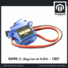 SG90 MG90 Tower Pro Micro Servo Motor 9g 180 360 Servo Motor for Arduino Robotic - SG90- 180°
 Arduino Uno Compatible SMD UNO R3 with Type B Cable - ATMEGA328P with CH340G-Microcontroller Project
 Joystick Module X Y Z axis 5 Pin Analog Joy Stick Controller for Arduino Robotic
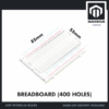 MB102 Breadboard 170 400 830 Holes Breadboard Donut Board Arduino Prototype Multi Color - BREADBOARD (400 HOLES)
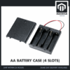 AA Battery Holder with Cover On/Off Switch 2/3/4 Slots Battery AA Holder Red/Black Wire - AA BATTERY CASE (4S)
 40pcs Dupont Wire 10cm 20cm 30cm for Breadboard DIY Experiment Jumper Wire Breadboard wire - DUPONT WIRE M-M 20CM
 40pcs Dupont Wire 10cm 20cm 30cm for Breadboard DIY Experiment Jumper Wire Breadboard wire - DUPONT WIRE M-F 20CM
Optional — for a sagging arm, a mains bench supply, or more joints
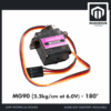 SG90 MG90 Tower Pro Micro Servo Motor 9g 180 360 Servo Motor for Arduino Robotic - MG90- 180°
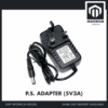 Power Supply Adapter DC Universal AC to DC Converter PSU 5V2A 5V3A 9V2A 12V2A - P.S. ADAPTOR (5V3A)
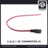 5.5x2.1mm DC Power Male Connector Plug Jack Adapter for Arduino DIY Electronics Projects - 5.5x2.1 DC CONNECTOR (F)
 16 Channel PWM Servo Motor Driver PCA9685 16 PWM Output with I2C Communication For Arduino Robotic
Metal-gear MG90 servos for the base and shoulder if the arm sags under its own weight; the 5V 3A adapter with a barrel-jack pigtail as the tidier bench alternative to batteries; the PCA9685 driver only once you outgrow four direct pins.
How do you give four servos their own supply?
The 4×AA battery case is the simplest correct answer, and its voltage lands where it should: four alkaline cells give 6.0 V nominal, four NiMH 4.8 V, both inside the SG90’s rated 4.8–6 V window and both able to deliver amps. Fresh alkalines read nearer 1.6 V each off-load, so a new pack meters about 6.4 V — harmless, because internal resistance pulls it back inside the window the moment a servo draws, and a reason not to reach for anything larger, because a 7.2 V pack has nowhere to sag to.
Run the pack’s red lead to the red rail of the breadboard and its black lead to the blue rail — stranded leads splay inside a breadboard hole, so tin them or twist each around a male jumper pin. Meter the two rails before a single servo goes in: an SG90 carries no reverse-protection diode, so one swapped pair kills all four at once and without a sound. All four servo red wires then go to the red rail, all four brown to the blue.
Then join the grounds. This is the step that gets skipped. A servo does not read your pulse as an abstract “pulse” — it reads the voltage on its orange wire relative to its own brown wire. If the battery’s negative and the Uno’s ground are not the same electrical node, those references drift apart and the servo sees a signal it cannot decode: the arm jitters, creeps, or does nothing. One black jumper from the Uno’s GND header to the blue rail fixes it.
Never connect the pack to the Uno’s 5V pin. That pin sits after the regulator, wired straight to an ATmega328P specified for a 5.5 V maximum operating voltage and a 6.0 V absolute maximum. A fresh pack of alkalines sits right on that ceiling, and with USB plugged in you would push it back into your computer’s port too. VIN fails differently: a linear regulator needs about a volt of headroom, so 6 V in cannot hold 5 V out. Keep the Uno on USB. For a mains bench supply instead of cells, the 5 V 3 A adapter with a barrel-jack pigtail onto the rails covers four stalled servos.
To run the arm away from a laptop, feed the board through its barrel jack instead: a 7–12 V pack or a 9 V PP3 is comfortable there, since the Uno and two joysticks together sit far under that 270 mA. The ban is on the servo rail, not on the board.
How do the four joints and two joysticks wire up?
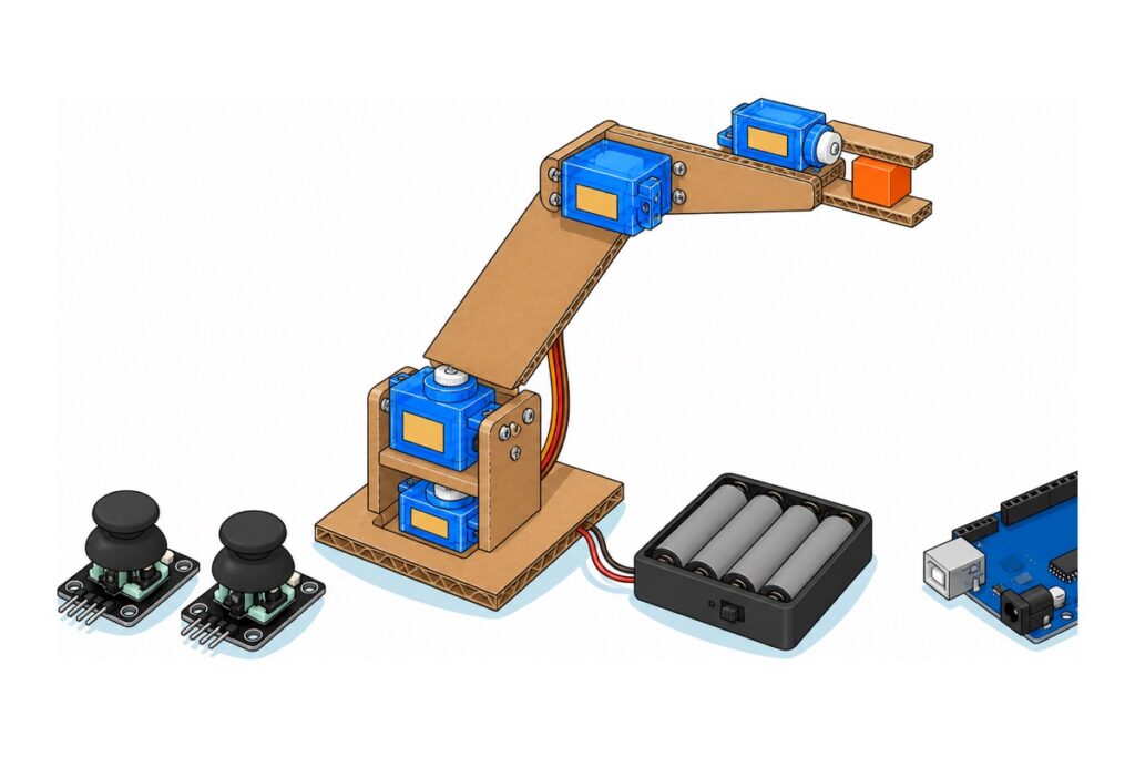
A minimal Arduino robot arm has four joints: base rotation about a vertical axis, a shoulder raising the upper arm, an elbow folding the forearm, and a gripper. Two joystick modules give exactly four analog axes — left stick for base and shoulder, right for elbow and grip.
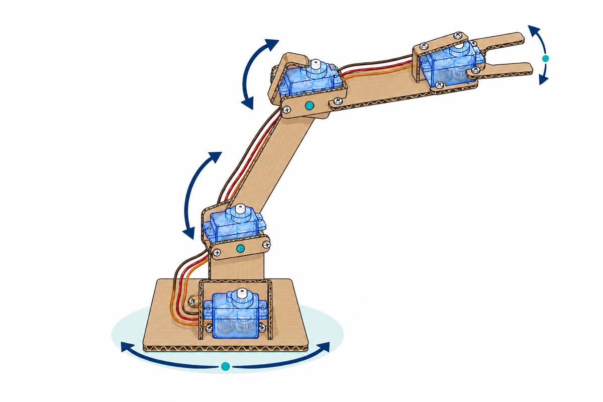
Each SG90’s lead ends in a black three-pin female socket, so male-to-male jumpers reach the Uno’s female headers and the breadboard rails. The joysticks are the opposite gender — right-angle male pins — so they take male-to-female jumpers; our jumper wire guide covers which end mates with what.
| From | To | Note |
|---|---|---|
| Servo orange (signal) ×4 | D9 base, D10 shoulder, D11 elbow, D3 gripper | Any digital pin works; the Servo library takes PWM off 9 and 10 regardless |
| Servo red ×4 | Breadboard red rail | From the battery — never from the Uno |
| Servo brown ×4 | Breadboard blue rail | |
| Battery + / − | Red rail / blue rail | Case switch is the kill switch |
| Uno GND | Breadboard blue rail | The common ground — mandatory |
| Uno 5V | Red rail on the breadboard’s other edge | The logic rail — joysticks only, never the servos |
| The two blue rails | Joined by one jumper | Battery, Uno and joysticks on one ground |
| Joystick 1: +5V, GND, VRx, VRy | Logic red rail, blue rail, A0, A1 | Base and shoulder |
| Joystick 2: +5V, GND, VRx, VRy | Logic red rail, blue rail, A2, A3 | Elbow and gripper |
| Joystick 2: SW | D2 | Park button, uses the internal pull-up |
The joysticks may take their 5 V from the Uno, and they are the only things that may: each HW-504 module is two 10 kΩ potentiometers across the rail, about half a milliamp per axis. VRx and VRy are the analog axes; SW is a push switch shorting to ground, not a third axis, so it needs a pull-up.
The direction of that rule matters as much as the rule. A joystick is a potentiometer, so VRx is a fraction of whatever voltage feeds it, and analogRead() measures that fraction against the Uno’s own 5 V as full scale: run a stick off the 6 V pack instead and a centred axis reads about 614 rather than 512, which the sketch reads as a stick held permanently over — the joint drifts on its own. The Uno has one 5 V pin and two sticks each want 5 V and GND, so give the breadboard’s other long edge that job: one jumper from Uno 5V to that red rail, both sticks’ +5V into it, their GND pins on the blue rail beside it, and one jumper tying that blue rail across to the battery’s. The two supplies share a ground, never a positive.
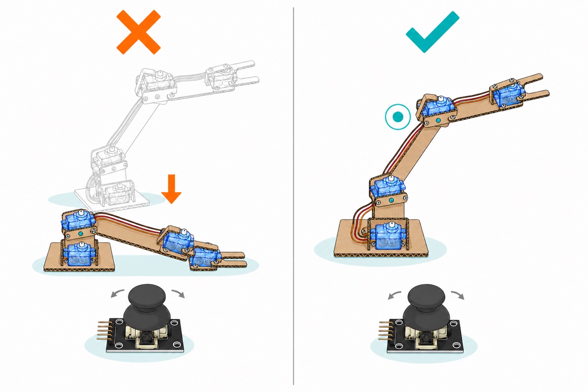
Why must the joystick set speed rather than angle?
An analog joystick is spring-loaded: release it and it returns to centre, where analogRead() reports roughly 512 of 1023. Map that straight onto an angle — the right approach for a pan-tilt head, as our joystick pan-tilt guide does — and centre means 90°. So the moment you let go, every joint is commanded back to 90° and the arm folds up.
Incremental control inverts that: deflection sets speed, not position. Every 20 ms the sketch measures how far the stick sits from centre and adds a proportional slice of a degree to a stored target angle. Push half way and the joint creeps; push fully and it travels about 60 °/s; let it centre and nothing is added, so the arm stays put.
Three details make that behave. A deadband of about 40 counts either side of 512 is subtracted before anything is added, because a resting stick never reads a clean 512 — the pot’s mechanical centre and ADC noise wander by several counts, and without it the arm creeps on its own. constrain() clamps each target between per-joint limits, so a joint cannot be driven into its own frame. And the target is a float, so gentle pushes accumulate fractions of a degree instead of rounding to nothing. The 20 ms tick itself is one servo refresh frame — the library emits one pulse per servo per frame, so a target updated faster never reaches the motor.
What does the Arduino robot arm code look like?
The sketch needs only the Servo library bundled with the Arduino IDE, and compiles to 5162 bytes of flash (16% of an Uno) and 282 bytes of RAM. Set the limit arrays to your arm’s real range first. AXIS_PIN decides which stick drives which joint and INVERT decides which way it turns: flip an INVERT entry for a joint that runs backwards, swap two AXIS_PIN entries if the wrong joint moves.
// 4-servo robot arm on an Arduino Uno, driven by two analog joysticks.
// The stick sets SPEED, not angle: push it and the joint creeps that way,
// let go and the joint stays exactly where it is. That is what lets an arm
// hold a pose - a direct analogRead-to-angle mapping would drop the arm
// the instant the stick springs back to centre.
//
// SERVO POWER DOES NOT COME FROM THE UNO. The four servo red wires go to a
// separate 4xAA pack (or a 5V supply); only the ground is shared.

#include <Servo.h>

Servo joint[4];                                     // base, shoulder, elbow, gripper

const uint8_t  SERVO_PIN[4] = {  9,  10,  11,   3 };  // signal pins (orange servo wire)
const uint8_t  AXIS_PIN[4]  = { A0,  A1,  A2,  A3 };  // stick 1 VRx/VRy, stick 2 VRx/VRy
const bool     INVERT[4]    = { false, true, false, false };
const uint8_t  MIN_DEG[4]   = { 10,  30,  20,  25 };  // mechanical limits - measure YOUR arm
const uint8_t  MAX_DEG[4]   = { 170, 150, 160,  90 };
const uint8_t  HOME_DEG[4]  = { 90,  90,  90,  60 };  // the parked pose

const uint8_t  PARK_BUTTON  = 2;                    // stick 2's SW pin, wired to D2
const int      CENTRE       = 512;                  // analogRead() at rest, 0..1023
const int      DEADBAND     = 40;                   // ignore this much wobble around centre
const float    MAX_STEP     = 1.2;                  // degrees per tick at full deflection
const unsigned long TICK_MS = 20;                   // one tick per servo refresh frame

float target[4];                                    // the pose we are commanding, in degrees
unsigned long lastTick = 0;

void setup() {
  Serial.begin(9600);
  pinMode(PARK_BUTTON, INPUT_PULLUP);               // SW shorts to GND when pressed

  for (uint8_t i = 0; i < 4; i++) {
    target[i] = HOME_DEG[i];
    joint[i].attach(SERVO_PIN[i]);
    joint[i].write(HOME_DEG[i]);
    delay(400);                                     // one joint at a time: four servos
  }                                                 // snapping together is the worst
                                                    // current spike the arm ever draws
  Serial.println(F("Arm parked. Servos must run from their own supply."));
}

void loop() {
  unsigned long now = millis();
  if (now - lastTick < TICK_MS) return;             // nothing to do between frames
  lastTick = now;

  bool parking = (digitalRead(PARK_BUTTON) == LOW);

  for (uint8_t i = 0; i < 4; i++) {
    if (parking) {
      // Crawl back to the parked pose at the same speed as a full stick push.
      if (target[i] < HOME_DEG[i]) target[i] = min(target[i] + MAX_STEP, (float)HOME_DEG[i]);
      else                         target[i] = max(target[i] - MAX_STEP, (float)HOME_DEG[i]);
    } else {
      int offset = analogRead(AXIS_PIN[i]) - CENTRE;
      if (abs(offset) <= DEADBAND) continue;        // stick at rest: no write, joint holds

      // Subtract the deadband so the joint starts from zero speed, not a jump.
      offset += (offset > 0) ? -DEADBAND : DEADBAND;

      float step = (float)offset * MAX_STEP / (float)(CENTRE - DEADBAND);
      if (INVERT[i]) step = -step;

      target[i] = constrain(target[i] + step, (float)MIN_DEG[i], (float)MAX_DEG[i]);
    }
    joint[i].write((int)(target[i] + 0.5));         // round, then send this frame's angle
  }
}
Two lines carry more than they look: the delay(400) staggers the servos so they reach home one at a time, turning the session’s worst current spike into four small ones, and the continue skips write() — a servo sent nothing holds its last angle, so doing nothing is the hold.
What do you build the frame from?
We sell the electronics, not the frame — there is no arm chassis or printed part in our catalogue. That matters less than it sounds: corrugated cardboard, cut with a craft knife and hot-glued, is the right material for version one, because you will redesign the geometry three times. Acrylic or 3 mm plywood is the upgrade.
Torque decides that geometry. Our SG90 is rated 1.3 kg/cm at 4.8 V — 1.3 kg held one centimetre from the shaft, so about 130 g at ten centimetres, minus the arm’s own weight. Keep segments to 10–12 cm, keep the gripper light, and expect the shoulder to give up first — it lifts the forearm, the elbow servo, the gripper and the load together, on the longest lever in the arm. The MG90 is the drop-in answer: same footprint and lead, 2.2 kg/cm at 6 V, metal gears instead of nylon.
Give every joint a pivot on the side opposite the servo — a bolt, or a screw through a cardboard washer, on the joint’s axis. An SG90’s output is a small nylon spline on a nylon gear train, made to turn a load rather than carry one, so a forearm hung off it alone drives every bending force into those gears. Weigh the base plate down too, or the base servo turns the base instead of the arm.
Fit the horns last. Let every joint reach its home angle before you drive a horn screw, then mount each horn mid-travel: assemble a servo at one end of its range and half your movement disappears into the frame. Our 180° vs 270° vs 360° servo guide covers horns and angle ranges — an arm wants 180° positional units, never continuous-rotation ones. Watching a four-joint frame go together helps here:
When do you outgrow four direct pins?
Three things push you to a PCA9685 16-channel driver: more joints than convenient pins; wanting pins 9 and 10 back for analogWrite(); or libraries that block interrupts for long stretches — SD cards, some displays — which makes timer-generated pulses jitter, while the PCA9685 pulses from its own oscillator regardless. Our PCA9685 guide covers that step. What it does not do is conjure current: its V+ screw terminal needs the same external supply.
Common mistakes we see
Proving it works with one servo on the Uno’s 5 V pin. One SG90 really does run from that pin, so the first test passes and the wiring looks settled. Two often look fine as well — then the third or fourth joint tips the rail over, everything fails at once, and the last change made gets the blame instead of the supply.
Leaving the grounds separate. Battery wired correctly to the servos but nothing between its negative rail and the Uno’s GND: the wiring looks right and the arm behaves randomly. Check this before rewriting code.
Guessing the joint limits. A servo commanded past what the frame allows does not give up — it sits at stall, drawing maximum current and heating, until something strips. That is what MIN_DEG and MAX_DEG prevent — start each joint timid at 60–120° and widen five degrees at a time, since the angle where a joint begins to buzz is the angle where it met its stop. The gripper needs the same care for a different reason: its closed limit is not a stop but the angle where the fingers just meet the object, and a degree past that is stall for as long as you hold the load.
Reading the hum as a fault. A positional servo is a closed loop: it compares its internal potentiometer against the pulse you sent and drives the motor until the two agree. Under load it never quite agrees, so it dithers around the target — that faint buzz is the joint working. A hum loud enough to shake the frame is the joint at its torque limit: shorten the segment, lighten it, or fit an MG90.
Reaching for a 9 V battery for the servos. Wrong twice: 9 V is above the SG90’s 6 V ceiling, and a PP3’s cells sag hard below the current four servos need.
FAQ
Can an Arduino Uno power 4 SG90 servos?
No. Four SG90s draw 0.4–1 A moving and up to 2.8 A at stall; the Uno’s rail offers roughly 450 mA on USB. It drives the four signal wires fine — the current needs its own pack.
Why does my Arduino reset when the robot arm moves?
The servos are pulling the 5 V rail below the ATmega328P’s brown-out threshold. The chip resets, the servos snap home, the rail collapses again. Give them their own supply and join the grounds.
What battery should I use for an Arduino robot arm?
Four AA cells: 6.0 V alkaline or 4.8 V NiMH, both inside the SG90’s 4.8–6 V window and both able to deliver amps. A 5 V 3 A adapter is the tidier alternative. Keep 9 V PP3 batteries off the servo rail — on the Uno’s own barrel jack they are fine.
Why does my robot arm drop when I let go of the joystick?
Because the sketch maps the stick reading onto an angle, and a released stick reads about 512 of 1023 — which becomes 90° on every joint. Add a slice of a degree per tick in proportion to deflection instead, and nothing when centred.
Do I need a PCA9685 driver for a 4-servo robot arm?
No. Four servos run off four Uno digital pins. A PCA9685 earns its place when you need more channels than pins, want pins 9 and 10 back for analogWrite(), or run libraries that disturb timer pulses. It supplies no current.
Last updated August 2026. Stuck? Chat with us on WhatsApp.
