

Tutorials
How to Use a Digital Multimeter (XL830L): Voltage, Continuity and Resistance
Jul
To use a digital multimeter you only need to master three modes: DC voltage (V⇤) for checking power supplies, continuity for finding broken wires, and Ohm (Ω) for reading resistor values. Put the black probe in the COM jack and the red probe in the VΩmA jack, pick a range higher than the reading you expect — and never leave the red probe sitting in the 10A jack.
What do the symbols on a multimeter dial mean?
The XL830L digital multimeter is a manual-range meter — meaning you choose the measuring range yourself, the meter does not choose it for you. That is exactly why its dial looks so crowded with numbers. In reality, every one of those numbers falls into just six groups of symbols.
| Symbol on the dial | What it measures | When you use it |
|---|---|---|
| V⇤ or DCV | DC voltage | Check batteries, an Arduino’s 5V rail, buck converter output. The mode you will use most often. |
| V∼ or ACV | AC voltage | AC supplies. This meter has only 200V and 600V ranges — no low range. |
| A⇤ (µA / mA / 10A) | DC current | Measure how many milliamps your circuit draws. The probes have to go inside the circuit, not touch it from the side. |
| Ω | Resistance | Read resistor values, check a motor coil, check a heating element. |
| Arrow pointing at a vertical line | Continuity + diode test | One and the same dial position. Find a broken wire, a cracked solder joint or a short — the meter beeps if there is a connection. You can also check whether a diode or LED is alive and work out which way round it goes. |
| hFE | Transistor gain | Push the transistor’s legs into the dedicated socket to check whether it is still good. |
Note one important thing: this dial has no AC current mode and no capacitance mode. That is simply not what a meter in this class does, so do not go hunting for them.

What you will need
| Item | Price | Qty | |
|---|---|---|---|
 XL830L Digital Multimeter with backlight Portable Multimeter Electronics ProjectMULTIME XL830L Digital Multimeter with backlight Portable Multimeter Electronics ProjectMULTIME | RM25.95 | ||
 Crocodile Clip Cables 46cm Alligator Clip Cable Multi ColorCROWIRE Crocodile Clip Cables 46cm Alligator Clip Cable Multi ColorCROWIRE | RM4.15 | Out of stock | |
 400 pcs 1/4W Resistor Pack Resistor Kit 20 Common Value with 20 each400RPAC 400 pcs 1/4W Resistor Pack Resistor Kit 20 Common Value with 20 each400RPAC | RM7.95 | Out of stock |
How do I measure DC voltage properly?
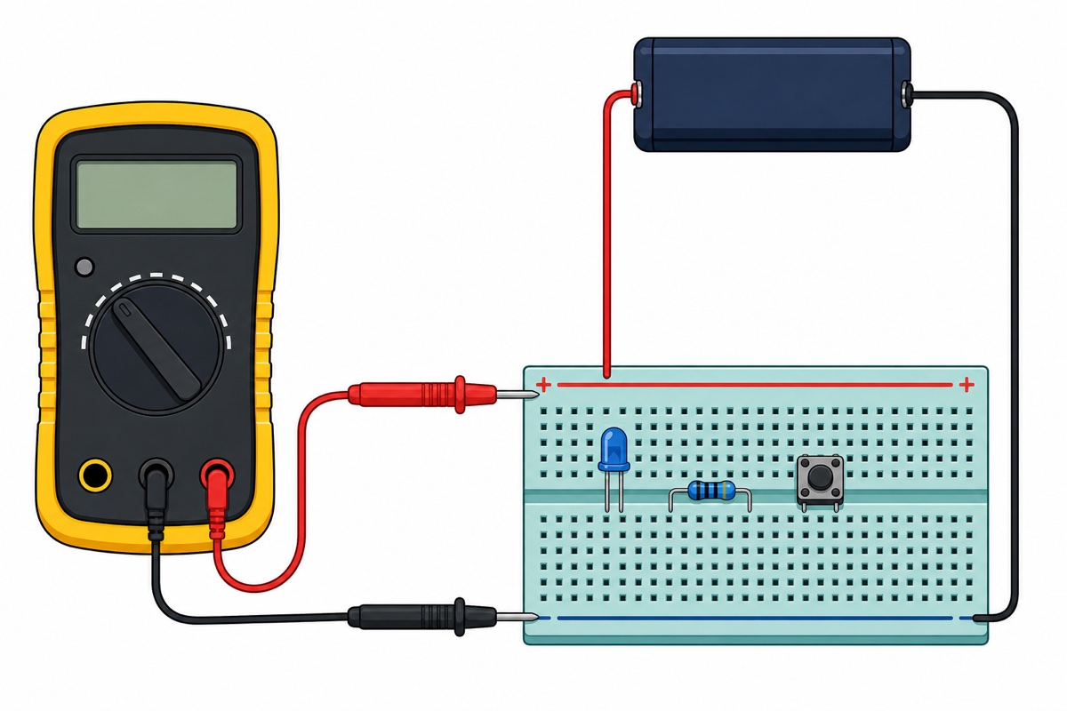
DC voltage is the measurement you need most often in Arduino work, and it is also the safest, because the probes only touch the outside of the circuit. Put the black probe in the COM jack and the red probe in the VΩmA jack — those two jacks alone cover 95% of your work.
Turn the dial to the V⇤ section, pick a range that is higher than the voltage you expect, then touch the black probe to GND and the red probe to the point you want to measure. If the display shows just a "1" on the left, the reading is over range — go up one step.
If the reading comes out negative, do not panic. It only means your probes are the other way round; the value itself is still correct. This meter does have a negative polarity indicator, so you will not damage anything.
One thing that rarely gets mentioned: this meter’s input impedance is roughly 1 MΩ in DC mode, not the 10 MΩ of an expensive meter. For batteries and power rails that is no problem, but on a voltage divider built from hundreds of kilo-ohms the meter itself draws current and the reading comes out lower than it should be.
When should you use continuity mode, and what does that beep mean?
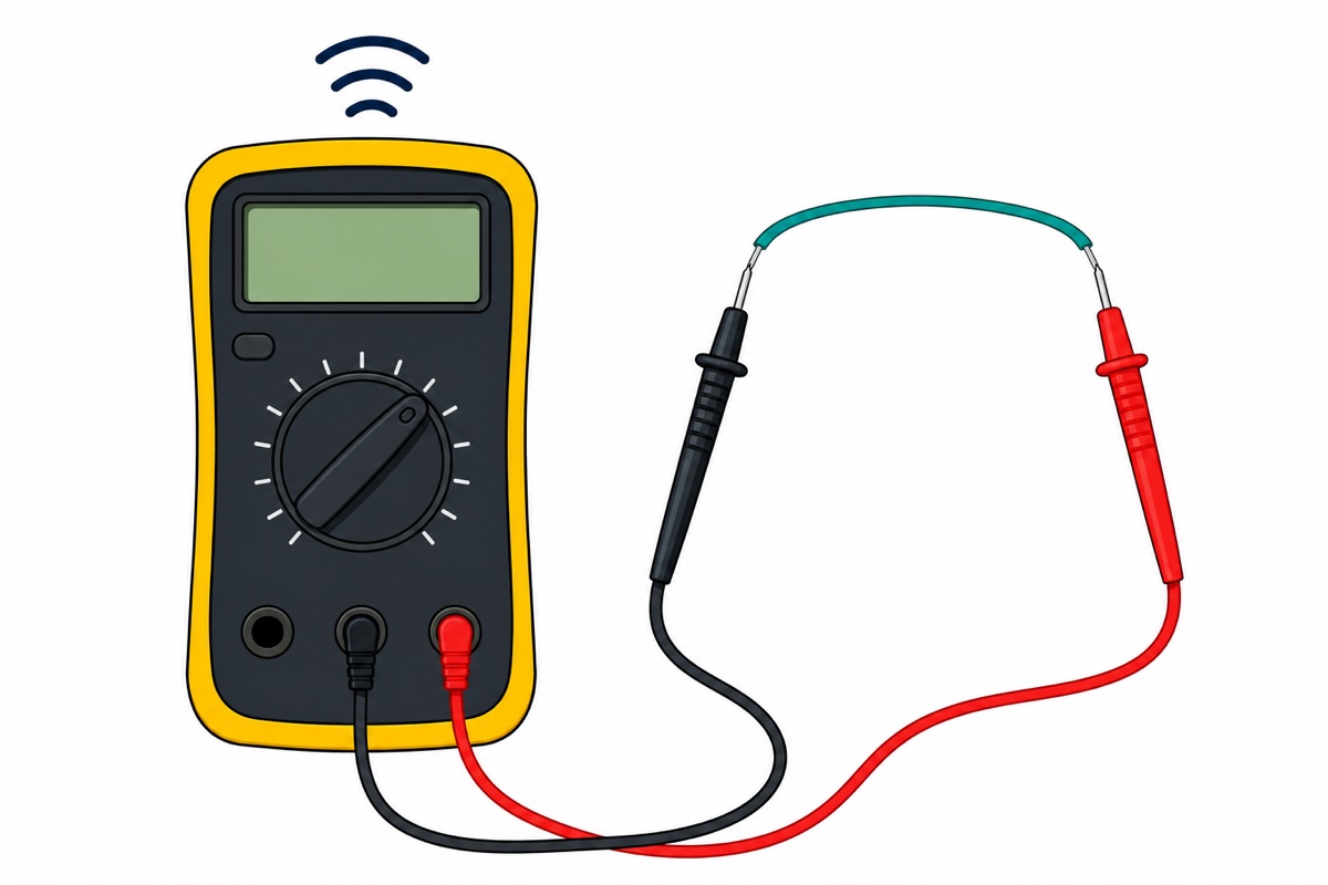
On the XL830L, continuity mode has no dial position of its own — it shares one with the diode test, the arrow-pointing-at-a-vertical-line symbol. The meter beeps when the resistance between the two probes drops to a few tens of ohms; independent testing found the beep starts around 72 Ω. So a beep means "there is an electrical path", and silence means "broken".
This is the single most useful mode for a beginner hunting down a fault. A jumper wire that looks fine but is broken inside its insulation, a solder joint with a hairline crack, a fuse that has blown, a scratched PCB track — this mode finds all of them in two seconds.
Two conditions are non-negotiable. First, the circuit must be completely powered down. Second, touch the two probes together first and listen for the beep — that is how you confirm the meter’s battery and your probes are still good before you trust a "silent" result.
For work like this, a set of crocodile clip leads saves a lot of time — clip one end of the wire, clip the other end, and both your hands are free to wiggle the wire while you listen for the beep cutting out. A wire whose beep stutters when you wiggle it is genuinely broken inside.
If you are chasing a solder joint problem, our guide on how to solder header pins shows what a proper joint looks like next to a cold one.
How do I read a resistor value with Ohm mode?
Ohm mode on this meter has five ranges: 200Ω, 2k, 20k, 200k and 2M. The rule is the same as for voltage — pick a range higher than the value you expect, and if the display shows "1", go up one step.
The fastest way to get comfortable is to grab a 400pcs resistor pack, pull out one resistor, guess its value from the colour bands, then confirm it with the meter. Do ten of them and you will not need a colour chart again.
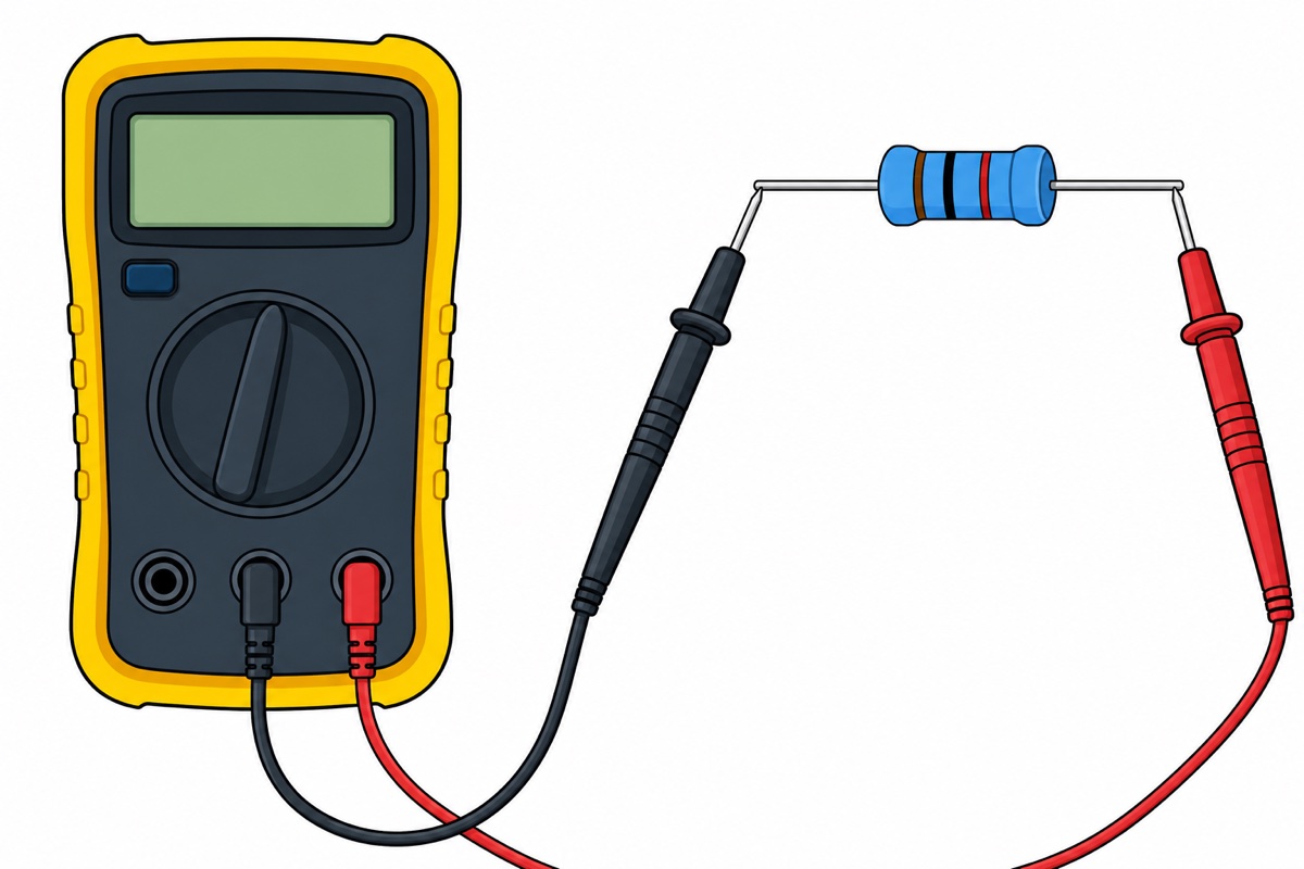
Two rules are compulsory in Ohm mode. The circuit must be dead and any charge left in the capacitors must be drained first — a still-charged capacitor gives nonsense readings and can damage the meter. And if the resistor is still soldered to the PCB, your reading will be lower than the real value, because the other components around it form parallel paths. For an accurate figure, lift at least one leg of the resistor.
Which range for what? Quick reference table
The XL830L table below answers the question that comes up most often while you are turning the dial. Keep it on your phone — after a week you will know it by heart.
| What you are measuring | Dial setting | Why that range |
|---|---|---|
| AA / AAA battery (1.5V) | V⇤ 2V | The 2V range gives you readings to three decimal places — fine enough to see a battery going flat. |
| 9V battery, LiPo cell, Arduino 5V rail | V⇤ 20V | This is the setting used most often in hobby electronics work. |
| Buck converter or 12V–24V power supply output | V⇤ 20V or 200V | Start at 20V; go up to 200V if the display shows "1". |
| Arduino circuit current below 200mA | A⇤ 200mA, red probe stays in the VΩmA jack | This path is protected by the 200mA/250V fuse. |
| 100Ω – 1.9kΩ resistor | Ω 2k | The 200Ω range runs out at 199.9Ω. |
| 2kΩ – 19kΩ resistor | Ω 20k | The very common 10k resistor lands here. |
| 20kΩ – 199kΩ resistor | Ω 200k | Covers 47k and 100k values. |
| Wires, fuses, jumpers, solder joints | Continuity | You only want a yes/no answer here, not a number. |
| LED or diode | Continuity / diode test | A red or green LED usually glows dimly when the red probe is on the anode leg. |
This short walkthrough is in Malay, but the dial positions and probe placement are easy to follow:
Why can the 10A jack kill your multimeter?
The fuse in the XL830L is an F 200mA/250V type, and this is the part most people misunderstand. That fuse only protects the low-current path that runs through the VΩmA jack. The 10A range has no fuse protection at all, and one variant of the manufacturer’s manual limits its use to 10 seconds at a time.
The number one way a cheap meter dies goes like this: someone measures current, then forgets to move the red probe back to the VΩmA jack, and goes straight on to poke the probes at a power supply to measure voltage. In current mode the meter is very nearly a dead short — so you have just shorted your power supply through the meter. On an expensive branded meter the fuse blows; on a cheap meter it is the PCB traces that burn instead.
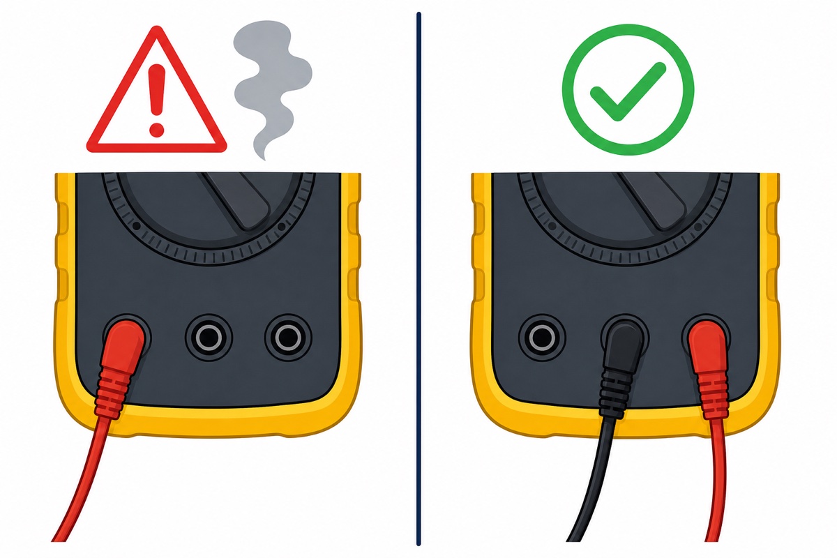
Build just one habit: the moment you finish measuring current, move the red probe straight back to the VΩmA jack. That one small habit saves more meters than every other piece of advice put together.
Common mistakes we see
The six multimeter mistakes below come up again and again among new users. Every one of them is avoidable.
- Measuring voltage while the probe is still in the 10A jack. This is the most expensive mistake of the lot, and there is only one reason for it — forgetting to move the probe back after measuring current.
- Measuring resistance on a circuit that is still live. Ohm mode works by pushing its own small current through the component. If the circuit still has power, the reading is nonsense and the meter is at risk.
- Measuring current the way you measure voltage. For current, the circuit has to be broken and the meter inserted as part of that path. Touching the probes across a power supply in current mode means a short.
- Throwing a resistor away because the reading does not match. A resistor still soldered to the board usually reads low because of parallel paths. Lift one leg before you draw any conclusion.
- Assuming continuity can test everything. A beep only means the resistance is below a few tens of ohms. Small motor coils and transformer secondary windings often beep even when they are perfectly fine — use Ohm mode for components like those.
- Blaming the meter when the readings are unstable. Touch the two probes together in continuity mode and wiggle them — if the beep stutters, it is the probes that are loose, not the meter.
Can I use this cheap multimeter on a 240V plug at home?
The XL830L multimeter can read up to 600V AC on paper, but we do not recommend using it on 240V mains wiring. The meter’s official manual does in fact state CAT II 600V — but that figure is printed by the manufacturer itself with no sign of independent laboratory verification, and an independent teardown found the 10A input completely unfused, with almost no real input protection. Its fuse is also soldered directly to the PCB.
240V on its own is already more than enough to kill a person. But what decides whether a given meter is safe to use there is transients — brief high-voltage spikes that appear on household wiring — and that is what a CAT rating actually tests for. A self-printed rating with no independent verification is no guarantee it can survive spikes like those. For Arduino work, batteries and buck converters, all of which sit below 30V, this meter is a good fit. For wall sockets, use a CAT III meter or call an electrician.
To sharpen your DC voltage skills, try wiring up an LM2596S buck converter and watching its output while you turn the trimmer — the steps are in our guide on adjusting an LM2596 to 5V. A multimeter is also the first tool you should reach for when an ESP32 is not detected or an upload fails, because power problems and broken wires are the two biggest causes.
For DC voltage practice (optional)
| Item | Price | Qty | |
|---|---|---|---|
 LM2596S DC-DC Buck Converter Step Down Power Module 4-40V to 1.25-37V Voltage Regulator Board - LM2596S BUCK CONVERTORLM2596X LM2596S DC-DC Buck Converter Step Down Power Module 4-40V to 1.25-37V Voltage Regulator Board - LM2596S BUCK CONVERTORLM2596X | RM4.95 |
Wire it up, turn the trimmer, and watch the meter reading change in real time.
FAQ
My multimeter only shows "1" — is it broken?
It is not broken. A lone "1" on the left means the reading is over the range you selected. Turn the dial one step higher. In Ohm mode, "1" also means an open circuit — there is genuinely no connection between the two probes.
Why is my voltage reading coming out negative?
Because the probes are the wrong way round — the red probe is sitting at a lower voltage than the black one. The value is still correct, only the sign is negative. The XL830L does have a negative polarity indicator, so nothing has been damaged.
Can the XL830L multimeter measure AC current?
No. The XL830L only measures DC current (200µA to 10A) and has no AC current mode at all. It has no capacitance mode either. For AC current you need a clamp meter or a meter with higher specifications.
Why doesn’t my resistor reading match the colour bands?
Three common reasons: the resistor is still soldered to the board, so parallel paths pull the reading down; the range you picked is too high, so the resolution is coarse; or your fingers are holding both legs of the resistor — your own body becomes a parallel path. Hold only the plastic part of the probes.
My multimeter’s fuse has blown. How do I replace it?
The XL830L’s fuse is a 200mA/250V type soldered directly to the circuit board, so replacing it needs soldering work — not just opening the cover and pulling it out. For a meter at this price, many people choose to buy a new unit instead. Avoiding it is still the best approach: always move the red probe back to the VΩmA jack as soon as you finish measuring current.
Last updated July 2026. Stuck? Chat with us on WhatsApp.

Pingback: Soldering Iron Guide: Why Soldering Won't Stick
Pingback: Boost vs Buck Converter: Which Do You Need?
Pingback: 18650 Battery Charger for a 3S Pack: Series vs Parallel
Pingback: How to Test a Capacitor With a Multimeter
Pingback: Breadboard Guide: Hidden Holes, Mini vs 400 vs 830