

Tutorials
18650 Battery Charger for a 3S Pack: Series vs Parallel
Aug
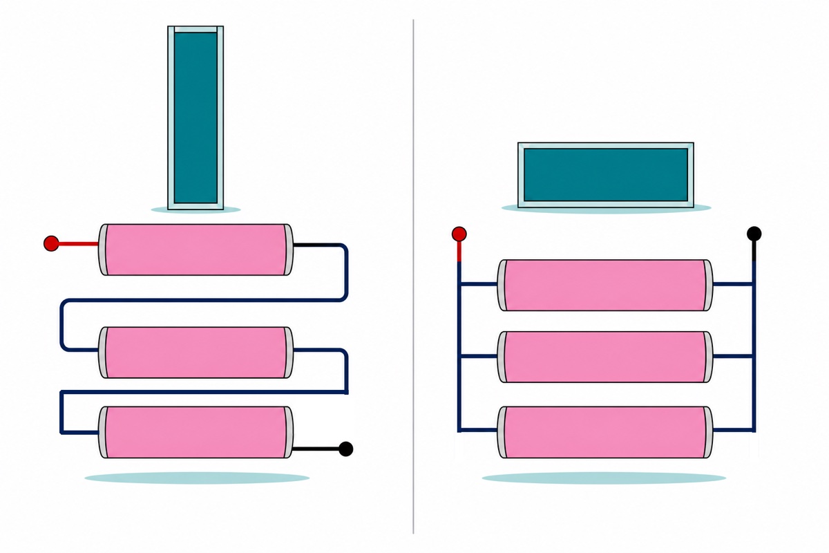
Three 18650 cells in a multi-slot holder do not make a bigger 3.7 V battery. Our multi-slot 18650 holders wire their slots in series, so the voltages add: three cells give an 11.1 V nominal pack that reaches 12.6 V full, at the capacity of one cell. A TP4056 can never charge that — it stops at 4.2 V, which is one cell.
Series or parallel — what does a three-slot holder actually give you?
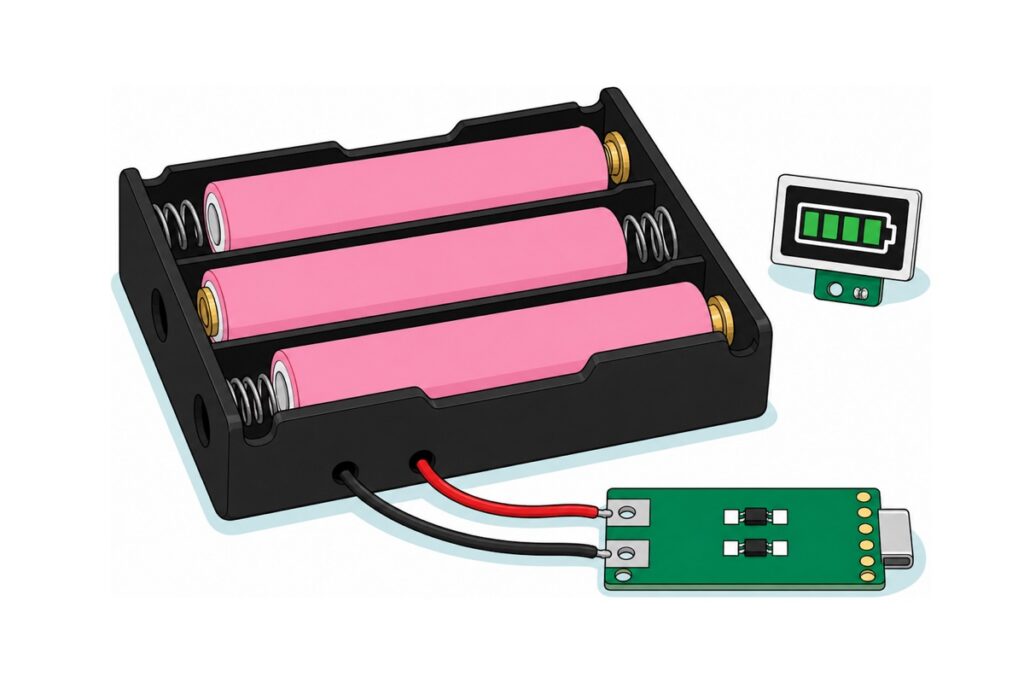
The 3-slot 18650 holder — battery casing, battery box, cell holder, all the same part — shows its wiring in its own moulding. One bay has the coil spring left and the brass button right, the next has them the other way round, the third swaps back. That zig-zag exists because each slot’s positive is strapped to the next slot’s negative inside the plastic — the definition of a series string — and the two leads that come out are its ends.
Series adds voltage and keeps capacity. Parallel is the opposite wiring and the opposite result — every positive joined to every positive, every negative to every negative — so the bank stays 3.7 V and the milliamp-hours add. That is the 1S2P people ask for by name, and it takes one single-slot holder per cell. Parallel cells equalise through each other the instant you connect them, limited only by the cells’ own internal resistance — well under a tenth of an ohm in a healthy 18650, so a 0.5 V gap between two of them is a several-amp short circuit until they meet in the middle. Match them to within about 0.05 V on a meter first and that surge becomes a fraction of an amp.
Series has a stricter version of the same rule, and it is why balancing exists as a separate job. The three cells carry one shared current, so the weakest empties first while the others still look healthy. Charging is worse: a charger that stops at 12.6 V is only ever measuring the sum, and 4.35 V + 4.15 V + 4.10 V comes to exactly the same 12.60 V as three cells sitting at 4.20 V. Nothing in the pack can tell those two apart, so the high cell goes a little over its limit every cycle and the spread widens. Buy the three together and check them with a multimeter before assembly — within about 0.05 V of each other.
How hard you may pull is set by the cell, not the pack, and it is quoted as a C-rate — a multiple of capacity. 1C is 2.2 A on a 2200 mAh cell and 1.2 A on a 1200 mAh one. Cobalt-oxide (ICR) 18650s of this class are specified around 2C maximum continuous — Samsung’s ICR18650-22F sheet gives 4400 mA for a 2200 mAh cell — so design at about 1C for cool cells and honest runtime. Series does not raise it: one shared current means an 11.1 V pack of 2200 mAh cells is still a 2.2 A pack, about 24 W.
The name 18650 is only a size: 18 mm across, 65 mm long. A 21700 is the same 3.7 V lithium chemistry in a 21 × 70 mm can — more capacity per cell, and too fat for any 18650 holder. Everything here about series, parallel, charging voltage and C-rate applies to that format unchanged; only the holder has to match the can.
| Wiring | What you get from 3 × 2200 mAh | Which holder | Charged by |
|---|---|---|---|
| Series (3S) | 11.1 V nominal, 12.6 V full, 2200 mAh, ~2.2 A | 18CASE3 multi-slot — series is built in | A 3S charging board |
| Parallel (1S3P) | 3.7 V nominal, 4.2 V full, 6600 mAh, ~6.6 A | Three 18CASE1 single holders, wired + to + and − to − | A TP4056 (slowly) or a boost/charge shield |
Parts list — a complete 3S 18650 pack with USB-C charging and a level indicator
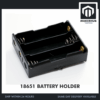 18650 Battery Holder 1/2/3/4 Slot 3.7V Battery Cell Housing Battery Case Battery Casing - 18650 BATTERY HOLDER (3)
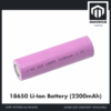 3.7V 18650 Battery Rechargeable Li-Ion Battery 1200mAh 2200mAh 3200mAh Flat Top - 18650 Li-Ion Battery (2200mAh)
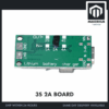 2S 3S 4S 1A 2A USB-C LI-ION CHARGER MODULE 18650 BATTERY CHARGING BOARD BUCK CN3304 - 3S 2A 18650 CHARGING BOARD
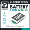 Battery LED Capacity Indicator Lithium Ion Battery Level Tester Green Display Battery like disply
 40pcs Dupont Wire 10cm 20cm 30cm for Breadboard DIY Experiment Jumper Wire Breadboard wire - DUPONT WIRE M-M 20CM
Useful alongside
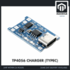 TP4056 18650 Battery Charger Module Lithium Ion Battery Li-ion Battery Charger Type C Micro USB - TP4056 CHARGER (TYPEC)
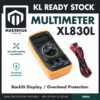 XL830L Digital Multimeter with backlight Portable Multimeter Electronics Project
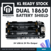 Dual 18650 Lithium Battery Holder Shield V3 Power Module 5V USB 3V Pin Output Charging
The TP4056 with Type-C is the correct charger for the SINGLE-cell lane, and worth having if some of your projects run on one cell. The XL830L multimeter is how you match cells before assembly and confirm every solder joint before the pack is live. The dual-18650 shield is the ready-made alternative when you want 5 V USB out and charging on one board instead of building a 3S pack.
Soldering is required. The charging board arrives as bare tinned pads — no terminal block, no header — and the indicator has two bare pads, so the holder’s leads solder straight to the board and a cut-down Dupont jumper carries the indicator. Two wires land on each of those pads — the holder’s and the indicator’s — so twist each pair of bare ends together and tin them as one joint rather than stacking a second blob onto a finished one.
New to that? Start with our soldering iron and flux guide. Leave the cells out of the holder until every joint is soldered and checked: with three cells in, those two leads are a live 12.6 V supply with no fuse and no switch of its own, and an iron that slips across them is a dead short through the cells. Low-voltage DC only, and check polarity twice before you heat anything.
Why won’t a TP4056 charge a 3S pack, and which 18650 battery charger does?
The TP4056 is a single-cell CC/CV charger: it pushes current until the cell reaches 4.2 V, then holds 4.2 V and tapers off. Present 4.2 V to a pack that sits between 9.9 V empty and 12.6 V full and no charging current flows at all — the charger regulates below the pack. It is not a harmless experiment either: the TP4056 data sheet rates its BAT pin at 7 V absolute maximum, a limit even a 2S pack at 8.4 V is already past, so hanging a 12.6 V pack on it is an overvoltage on the chip, not a slow charge. It stays the right chip for one cell, which our TP4056 guide covers.
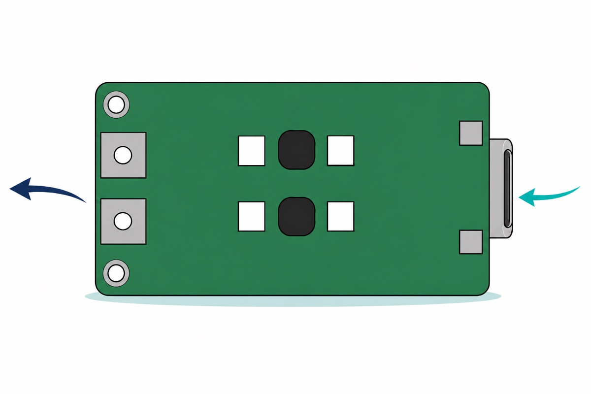
The 3S charging board is a PFM boost charger, not a step-down. Its silkscreen says IN 3–6 V: it takes 5 V from the USB-C socket and steps it up to the 12.6 V the pack needs, running the same CC/CV curve at three cells’ worth of voltage. Two rows of select pads sit in the middle — the row marked OUT → over 2S / 3S / 4S marks the cell count the board is built for, the row marked IN → over 1A / 2A / 4A marks the input current limit. On the 3S 2A version both middle pads arrive bridged with solder from the factory. Leave them as they came and buy the variant that matches your pack: the three-cell controller regulates to 12.6 V internally, and 12.6 V pushed into a two-cell pack is a fire.
That input row is why the number on the box is not the number the pack sees: the controller’s current-sense resistor sits in the supply path ahead of the inductor, so what it limits is what goes in. 2 A at 5 V is 10 W in; a boost of this class runs near 93% efficient, so about 9.3 W comes out; and 9.3 W ÷ 12.6 V is 0.74 A into the pack. The 1A version halves that to 0.37 A.
So your 5 V source must genuinely hold 2 A: a bench 5 V supply on the VIN and GND pads, or a charger actually rated 2 A through a USB-A to USB-C cable, not a spare phone port. And 0.74 A into 2200 mAh cells is 0.34C, comfortably inside the 0.5C rule of thumb, filling the pack in about three and a half to four hours with the CV tail. One cable note while you are there: reach for A-to-C before C-to-C, because a USB-C source negotiates with the sink before it turns its output on at all — a C-to-C lead that gives no charge light is usually a handshake that never happened, not a dead board.
What it does not do matters as much. Customers ask us “kamu ada jual BMS protection bateri 18650 tak?” and this is not that board: it has BAT and GND on the battery side and nothing else — no balance leads reaching the individual cells, no protection MOSFETs in the discharge path. Charging, balancing and discharge protection are three separate jobs, and this board does the first.
A 3S BMS is the other two: balance leads tapping every cell junction so it can bleed the high cell down, and MOSFETs sitting in the discharge path to open the circuit on over-discharge, over-current or a short. Different board, different place in the circuit — between pack and load, not on the charge input — and no charging board substitutes for it. Protection here is procedural: matched cells starting level, the indicator watching the pack, a meter across each cell every few cycles.
| Connect | To | Why |
|---|---|---|
| Holder RED lead | Charging board BAT pad (left edge, lower) | Pack positive, 12.6 V full |
| Holder BLACK lead | Charging board GND pad (left edge, upper) | Pack negative |
| Indicator + pad | Same junction as BAT | It measures the whole pack |
| Indicator − pad | Same junction as GND | Shared reference |
| 5 V 2 A source | USB-C socket (or the VIN/GND pads on the right edge) | Charger input, boosted to 12.6 V |
| Your load | Same BAT / GND junction | The board is not in the discharge path — switch the load off while charging, so the charger only sees the pack |
That last row is worth spelling out: the board has no power-path stage, so it cannot charge the pack and run the project at the same time. One node feeds the cells and the load together, and in the constant-voltage tail the charger waits for a current that a live load never lets fall to its termination threshold — so it holds 12.6 V indefinitely instead of stopping, and a pack held full for hours it did not need ages faster for it.
Which wiring you wanted is decided by the load, not by the holder. 9.9–12.6 V suits motors, pumps and 12 V LED strip directly; a 5 V or 3.3 V board does not, and needs a step-down converter in between — a buck module set to 5 V, sized for the current the project really draws, its input on the same BAT and GND junction. Our buck versus boost guide covers picking one. If all you want is longer runtime for one 3.3 V board, a parallel bank on a single-cell charger is simpler: series buys voltage, and voltage is all it buys.
What is the LED capacity indicator actually telling you?
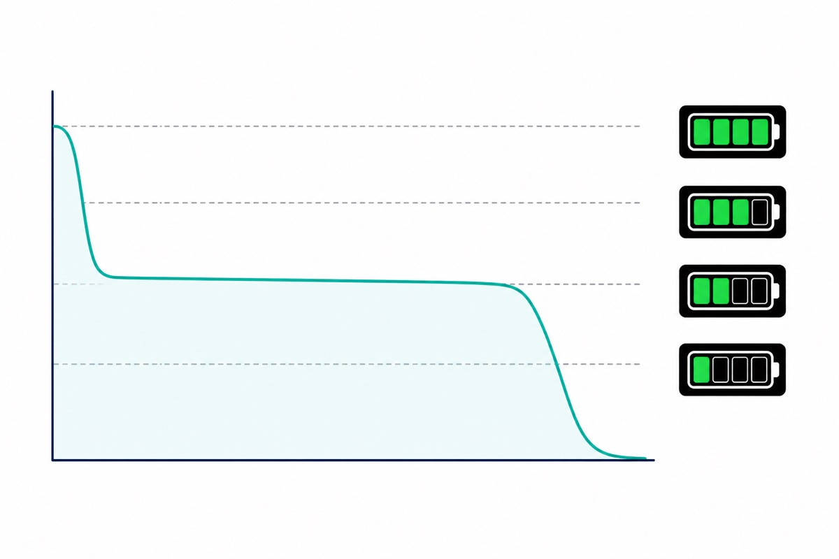
The battery indicator is a voltmeter with four thresholds, not a fuel gauge — display based on voltage level, as its own card puts it. With N cells selected, one bar lights above N × 3.3 V, two above N × 3.5 V, three above N × 3.7 V, four above N × 3.9 V, and all four go dark below N × 3.3 V. You set N by bridging the matching S pad on the rear — S3 here, with no other pad closed.
Get it wrong and the display still lights, which is what makes it confusing: a 12.6 V pack on the one-cell scale is above every threshold there is, so it shows four bars for ever. A display that never drops is an S-pad problem, not a battery problem.
The + and − pads at the board edge are the only wires it needs — and they are permanently live. The display sits straight across the pack with no switch of its own, and this module family draws about 5 mA all the time, roughly 120 mAh a day, so a pack left wired to it for a few weeks will walk itself flat and then keep going down. Put a small switch in the indicator’s + lead, or lift one cell out of the holder, whenever the project is going in a drawer — and store the pack around half charged rather than full: lithium cells age fastest sitting at 4.2 V.
| Bars lit | Per cell | Your 3S pack reads |
|---|---|---|
| 4 | above 3.9 V | above 11.7 V |
| 3 | above 3.7 V | above 11.1 V |
| 2 | above 3.5 V | above 10.5 V |
| 1 | above 3.3 V | above 9.9 V |
| 0 | below 3.3 V | below 9.9 V — stop |
Set those thresholds against how a lithium cell really discharges and the display’s odd behaviour resolves. A Li-ion cell spends most of its stored energy on a flat plateau between roughly 3.9 V and 3.6 V, then falls away quickly below 3.5 V. Three bars is therefore not “three quarters left” — it is most of the runtime, and two bars to nothing happens fast.
The last bar is a stop sign rather than a warning: nothing in this pack will cut your load off for you, and a cell dragged below about 2.5 V loses capacity permanently — one left flat should not simply be put back on charge. Pull the load at one bar, not at zero. Seeing the module wired and set once helps:
A microcontroller already in the project can print the real number instead of a bar. This sketch does that on an Arduino UNO through a 100 kΩ / 47 kΩ divider, turning 12.6 V into 4.03 V at A0 while drawing 86 µA. Note what it reports: an average. A pack averaging 3.7 V could be three cells at 3.7 V, or one at 3.2 V and two at 3.95 V — which is why the per-cell meter check still matters.
// PackWatch - read a 3S 18650 pack's voltage on an Arduino UNO and print
// the same number the LED capacity indicator is deciding its bars from.
//
// Divider:  pack BAT+ --[100k]--+--[47k]-- pack BAT- (tied to Arduino GND)
//                               |
//                               +-- A0
// 12.6 V full pack -> 12.6 * 47 / 147 = 4.03 V at A0, safely under the 5 V ADC ceiling.
// The divider draws 12.6 / 147000 = 86 uA, so it will not flatten the pack.
// SAFETY: connect the divider to the pack only, never across a cell already
// wired to something else, and common the grounds before powering anything.

const int   PIN_PACK = A0;
const float R_TOP    = 100000.0;   // ohms, pack positive to the tap
const float R_BOTTOM =  47000.0;   // ohms, tap to ground
const float VREF     = 5.00;       // measure the UNO's 5V pin and put the real figure here
const int   CELLS    = 3;          // 3S pack: three cells in series

// Undo the division: the tap only sees R_BOTTOM / (R_TOP + R_BOTTOM) of the pack.
const float DIVIDER  = (R_TOP + R_BOTTOM) / R_BOTTOM;   // 3.128

// The indicator lights a bar each time the pack passes CELLS x these volts.
const float BAR_V[4] = { 3.3, 3.5, 3.7, 3.9 };

int barsFor(float packVolts) {
  int bars = 0;
  for (int i = 0; i < 4; i++) {
    if (packVolts >= CELLS * BAR_V[i]) bars = i + 1;
  }
  return bars;
}

void setup() {
  Serial.begin(9600);
  Serial.println(F("PackWatch - 3S 18650 pack monitor"));
}

void loop() {
  // Average 16 samples: the last ADC bit rattles on a real load.
  long sum = 0;
  for (int i = 0; i < 16; i++) {
    sum += analogRead(PIN_PACK);
    delay(2);
  }
  float counts = sum / 16.0;

  float vTap  = counts * (VREF / 1023.0);   // volts at the tap
  float vPack = vTap * DIVIDER;             // volts across the whole pack
  float vCell = vPack / CELLS;              // average per cell - NOT each cell

  Serial.print(F("pack "));
  Serial.print(vPack, 2);
  Serial.print(F(" V | average cell "));
  Serial.print(vCell, 2);
  Serial.print(F(" V | indicator should show "));
  Serial.print(barsFor(vPack));
  Serial.println(F(" bar(s)"));

  // Below 3.0 V per cell average, at least one cell is already lower. Stop.
  if (vCell < 3.0) {
    Serial.println(F("LOW - disconnect the load and charge the pack"));
  }

  delay(1000);
}
Common mistakes we see from real customers
“The battery shield turns off the power after awhile on its own. How do I solve it?” Almost never a dead cell or a bad joint. Power-bank style boost boards watch their own output current and shut down when the draw stays very low — the threshold varies by board, commonly somewhere between about 30 mA and 100 mA, exactly where a sleeping ESP32 or an idle Arduino lives. On our dual-18650 shield the control is on the board: the slide switch at the top-right corner reads HOLD / NORMAL, and HOLD keeps the output alive at low draw until the low-voltage cutoff. Deep-sleep currents can still fall through even in HOLD, so the other honest answers are a periodic dummy load — 100 mA for a second, now and then — or building the 5 V rail from plain parts instead of a power-bank board — a TP4056 feeding a separate boost module has no output-current watchdog anywhere in it, so nothing is in a position to decide your project has gone idle. The combined charge, protect and boost module puts those same three jobs on one board:
Expecting a multi-slot holder to be parallel. One customer wrote “sy minta cancel jumpa yg lain sy jumpa holder parallel” — cancelling to hunt a parallel holder. Multi-slot is series; parallel is one single-slot holder per cell.
Charging while the load is still running. A bare TP4056 shares one node with the load, so the load’s draw is added to what the charger measures and termination goes wrong — the cell left half full, or trickled indefinitely. Boards that handle this use a power path: the input feeds the load directly and charges the cell with what is left over, so the charger only ever sees the cell. If your project must run while charging, look for power-path or load-sharing named explicitly in the board’s own description.
Treating an amp rating as a promise. “whats the max discharge current for 1200mah” — asked twice, forty seconds apart. 1A and 2A on the charging board are input limits, not pack current, and a burst figure on any cell’s spec sheet is not its continuous rating. For that 1200 mAh cell: design around 1.2 A continuous. If the load wants more, the answer is more cells in parallel, not a braver number.
FAQ
Is a 3-slot 18650 holder series or parallel?
Series — the alternating spring and button contacts strap each slot’s positive to the next slot’s negative. Three cells give 11.1 V nominal, 12.6 V full, at one cell’s capacity.
Can I charge a 2S or 3S pack with a TP4056?
No. It terminates at 4.2 V, below even a 3S pack’s empty voltage, so no charge current flows — and its BAT pin is rated 7 V absolute maximum, so wiring a 2S or 3S pack to it can damage the chip. A 3S pack needs a board that terminates at 12.6 V.
What does the 1A or 2A on the charging board mean?
The input current limit at 5 V, not the current reaching the cells. At 3S the 2A version puts about 0.74 A into the pack (5 V × 2 A × 93% ÷ 12.6 V), the 1A version about 0.37 A.
Can I charge the pack while the project keeps running?
Not on this board, and not on a bare TP4056 — neither has a power-path stage, so the load’s current confuses the charger’s termination and the charge never finishes. Boards that can do it name power path or load sharing in their own description.
What is the maximum discharge current for an 18650 cell?
Design at 1C — 1.2 A from a 1200 mAh cell, 2.2 A from a 2200 mAh one — and the cells stay cool and hold their voltage under load. ICR 18650s of this class are specified at around 2C maximum continuous, so 2.4 A and 4.4 A are ceilings rather than working figures, and a burst number is neither. Series does not raise any of it: all three cells carry the same current.
Does the charging board also protect and balance the pack?
No, it charges only — no balance leads to the individual cells, no protection MOSFETs in the discharge path. Start from matched cells, watch the indicator, meter each cell every few cycles.
Last updated August 2026. Stuck? Chat with us on WhatsApp.

Pingback: Mini Solar Panel: Which 5V or 6V One for Your Project?
Pingback: DRV8833 vs L298N: Which Motor Driver to Buy