

Tutorials
Boost or Buck Converter? How to Choose the Right One
Aug
Put your source voltage next to the voltage your load needs. Source higher — 12 V down to 5 V — buy a buck (step-down) converter such as the LM2596 or XL4016. Source lower — a 3.7 V cell up to 5 V — buy a boost (step-up) such as the MT3608 or XL6009. None works in both directions.
The other half of the decision is what not to reach for. A linear regulator and a two-resistor divider both produce a lower voltage, and neither one replaces a DC-DC buck converter; a mains transformer is a different animal again. The same arithmetic that separates them explains why the amp figure printed on a converter is not the amps you get.
Buck or boost — which direction do you actually need?
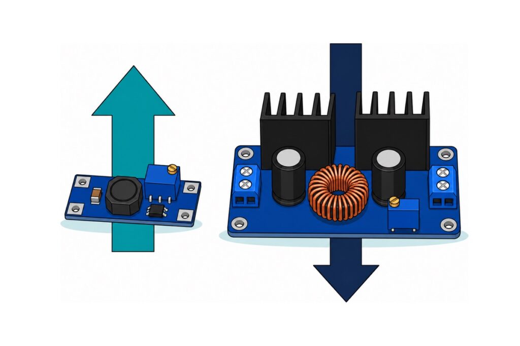
The buck and the boost are built from the same three parts — a switch, an inductor and a diode — wired in a different order, and that order fixes the direction. In a buck the inductor sits between switch and load, so the load sees the input only part of each cycle and the average is lower. In a boost the inductor charges straight from the input, then the switch opens and its collapsing magnetic field pushes that stored energy through a diode on top of the input voltage. A boost output can therefore never fall below its input, nor a buck output reach its input: the topology sets the direction, not the trimmer.
Both directions want margin. The LM2596’s internal switch is a bipolar transistor that still drops well over a volt when it is fully on, and that drop comes off the input before the inductor ever sees it — so 12 V in will not hold 11.5 V out, and about 1.5 V of headroom is the sensible allowance. A boost has the mirror problem for a different reason: its output is set by how long the switch stays on each cycle, and only a small step up asks for an on-time shorter than the controller can actually produce. Below that floor it stops regulating smoothly and skips pulses instead, so the output wanders and ripples. Give a boost a real ratio to work with.
| Module | Direction | Input | Output | Comfortable continuous output | Connections |
|---|---|---|---|---|---|
| MT3608 | Boost (step-up) | 2–24 V | Up to 28 V, always above the input | ~1 A at 3.7 V → 5 V; less as the ratio grows | Four bare solder pads · 36 × 17 mm |
| XL6009 | Boost (step-up) | 5–32 V | Up to about 35 V on this module | ~1.5 A at 12 V → 24 V | Four bare solder pads · 43 × 21 mm |
| LM2596S | Buck (step-down) | 4.5–40 V | 1.25–37 V, ~1.5 V below input | ~2 A (3 A chip, no heatsink fitted) | Four bare solder pads · 43 × 21 mm |
| XL4016 | Buck (step-down) | 8–36 V (40 V absolute max) | 1.25–32 V | Up to 8 A with its heatsinks and airflow | Blue screw terminals · large board |
The four converters compared — alternatives, not a kit: buy the one that matches your direction
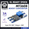 MT3608 Adjustable Step-up Convertor Boost Converter Switching Boost Converter for Arduino Project
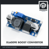 XL6009 Adjustable Step Up Converter Boost Converter Module XL6009E / XL6009D Display - XL6009 BOOST CONVERTOR
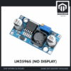 LM2596S DC-DC Buck Converter Step Down Power Module 4-40V to 1.25-37V Voltage Regulator Board - LM2596S BUCK CONVERTOR
 XL4016 DC-DC Buck Converter Step Down Power Supply Module 8A 300W High Power Voltage Regulator
What the bench work needs
| Item | Price | Qty | |
|---|---|---|---|
 XL830L Digital Multimeter with backlight Portable Multimeter Electronics ProjectMULTIME XL830L Digital Multimeter with backlight Portable Multimeter Electronics ProjectMULTIME | RM25.95 | ||
 Power Supply Adapter DC Universal AC to DC Converter PSU 5V2A 5V3A 9V2A 12V2A - P.S. ADAPTOR (12V2A)PSA1202 Power Supply Adapter DC Universal AC to DC Converter PSU 5V2A 5V3A 9V2A 12V2A - P.S. ADAPTOR (12V2A)PSA1202 | RM15.95 | Out of stock |
Every module here leaves the factory at whatever voltage its trimmer happened to be turned to, so you set the output with a multimeter across the output pads BEFORE the load is connected. The 12V 2A adapter is a convenient bench input for a step-down test; a boost module runs from a battery or any lower supply you already have.
Every converter here is DC in, DC out. The 12 V adapter is the part that deals with mains; the converter never touches it, and a buck is not a mains step-down transformer even though both hand you a smaller voltage. Nor do these isolate — IN− and OUT− are the same copper, so input and output share one ground. Low-voltage DC only.
The boost topology carries one more consequence worth knowing before you wire anything. Its inductor and catch diode form a permanent path from input to output, so a boost cannot disconnect its own output: short that output and the short lands on your source through the path rather than on the chip, and an 18650 will push tens of amps into it. Feed a 3.7 V → 5 V module 12 V by mistake and about 11.5 V reaches the load whatever the trimmer says. A buck opens its switch when its chip shuts down; a boost has no such off, so put the on/off switch and any fuse on its input side.
No module here is a buck-boost. If your source crosses the output — a Li-ion cell falling from 4.2 V to 3.0 V while you need 3.3 V — a buck fails at the bottom of the discharge and a boost fails at the top. Boost the cell to a clean 5 V with a battery module such as the 18650 charge-and-boost board and take 3.3 V from your board’s own regulator. Where the inductor sits in each topology:
Why is the amp number on a converter never the amp number you get?
A switching converter is not a valve that throttles voltage; it is an energy pump. A MOSFET chops the input at a fixed rate — 150 kHz on the LM2596, 180 kHz on the XL4016, 400 kHz on the XL6009, 1.2 MHz on the MT3608 — and each chop parks energy in the inductor, which hands it on at a different voltage. Almost nothing is discarded, so Pin ≈ Pout ÷ η, with η about 0.85–0.92 at sensible ratios and falling as the ratio grows — TI’s own figure for the LM2596 at 12 V in, 3 V out, 3 A is 73%.
Step down and the current goes up. 12 V in, 5 V out, a 2 A load is 10 W leaving. At 90% efficiency the input must supply 11.1 W, and 11.1 W ÷ 12 V = 0.93 A — the supply hands over less current than the load receives.
Step up and the current goes down. A 3.7 V cell, 12 V out, a 0.5 A load is 6 W leaving. At 85% the cell supplies 7.1 W, and 7.1 W ÷ 3.7 V = 1.9 A drawn from the battery — nearly four times the output current. That 1.9 A has to be genuinely available: a protected 18650 typically trips around 2–3 A and a USB port offers 0.5 A, which is why a boost that behaved on a bench supply browns out on the real source.
Now the printed rating makes sense. The 4 A on the MT3608 and XL6009 data sheets is an internal switch current limit, and on a boost that switch sits in the input path. Run it backwards at 3.7 V → 5 V: a 4 A input ceiling allows at most 4 × 3.7 × 0.9 ÷ 5 ≈ 2.7 A out — and long before that the 22 µH inductor and a 36 × 17 mm board are too hot to hold. About 1 A is comfortable at that ratio; a bigger ratio pushes it lower.
On a buck the input current is the smaller number, so the 3 A-class LM2596 can be honest about its rating — provided the heat escapes. Its TO-263 tab sits on a modest copper pad with no heatsink fitted, so about 2 A is the comfortable figure. The XL4016 carries two finned heatsinks and a thick-copper toroid for a reason: 5 V at 8 A is 40 W delivered, and 10% loss is 4.4 W of heat to shed. Expect warm heatsinks and wire suited to the current — 8 A wants roughly 1.5 mm² (16 AWG).
Buck converter vs voltage divider — why not just use two resistors?
A voltage divider really does produce a fraction of its input: Vout = Vin × R2 ÷ (R1 + R2). Feed 12 V into two 1 kΩ resistors and the midpoint sits at 6 V — as long as nothing is connected. Hang a 100 Ω load on it and the load joins the divider, parallel with the lower resistor: 1 kΩ ∥ 100 Ω = 90.9 Ω, so the midpoint falls to 12 × 90.9 ÷ 1090.9 = 1.0 V — a sixth of its reading, the moment it was given a job.
Smaller resistors only move the cost. A divider is stiff only while its own current dwarfs the load’s, so holding 6 V into a 0.5 A load means pushing about 5 A through the divider itself: R1 near 1.1 Ω, R2 near 1.2 Ω, roughly 33 W burnt in one and 30 W in the other, continuously, load or no load. Sixty-odd watts of resistors to deliver three. And even then it would sag with every change, because a divider has no feedback: nothing in it measures the output and corrects. It is arithmetic, not regulation, and must never power anything.
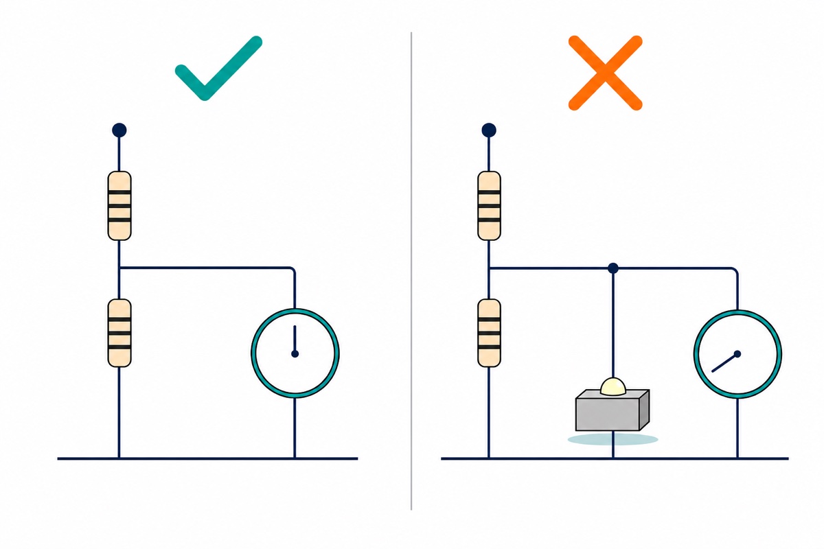
A divider’s real job is on a signal, scaling a voltage so a 5 V analogue input can read it; there it draws microamps and nothing collapses. This sketch turns an Arduino into a rail monitor — 100 kΩ from the converter’s OUT+ to A0, 22 kΩ from A0 to the shared ground — for rails up to about 27 V. That tap’s own source impedance is about 18 kΩ, above the roughly 10 kΩ the ATmega328P’s ADC is optimised for, so add a 100 nF capacitor from A0 to ground — it keeps the ADC’s sampling capacitor fed and smooths the switching ripple at the same time. Set the output with a multimeter first.
// Rail Watch - read a DC-DC converter's output voltage on an Arduino UNO.
//
// Divider:  converter OUT+ --[100k]--+--[22k]-- GND (shared with converter OUT-)
//                                    |
//                                    +--[100nF]-- GND   (feeds the ADC sample cap)
//                                    |
//                                    A0
// The divider draws only about 0.1 mA on a 12 V rail, 0.2 mA at 24 V.
// That is why it works here as a sensor and fails as a supply.

const int   PIN_RAIL = A0;
const float R_TOP    = 100000.0;  // ohms, converter OUT+ to the tap
const float R_BOTTOM =  22000.0;  // ohms, tap to ground
const float VREF     = 5.00;      // measure the 5V pin with a multimeter, put it here

// The tap only sees R_BOTTOM / (R_TOP + R_BOTTOM) of the rail, so scale back up.
const float DIVIDER  = (R_TOP + R_BOTTOM) / R_BOTTOM;   // 5.545

void setup() {
  Serial.begin(9600);
  Serial.println(F("Rail Watch - reading A0"));
}

void loop() {
  // Average 16 samples: the last ADC bit rattles on a switching rail.
  long sum = 0;
  for (int i = 0; i < 16; i++) {
    sum += analogRead(PIN_RAIL);
    delay(2);
  }
  float counts = sum / 16.0;

  float vTap  = counts * (VREF / 1023.0);   // volts at the tap
  float vRail = vTap * DIVIDER;             // undo the division

  Serial.print(F("rail = "));
  Serial.print(vRail, 2);
  Serial.println(F(" V"));

  delay(500);
}
Buck converter vs linear regulator — when is a linear the right chip?
A linear regulator — a 7805, an AMS1117-3.3 — is a transistor acting as an automatically adjusted resistor in series with the load, inside a feedback loop that keeps the output steady. That loop is what a divider lacks, so a linear genuinely regulates. But the full load current flows through the pass transistor, and every volt it removes is burned there. At 12 V in, 5 V out, 1 A, that 1 A crosses a 7 V drop — 7 W of heat, an efficiency of 5 ÷ 12, about 42%.
Two things follow. A linear can never step up, because a series resistance can only lose voltage: its output stays below its input by at least the dropout, roughly 2 V on a classic 7805. It is right where the switcher’s advantage vanishes: small drops at small currents (5 V to 3.3 V at 100 mA wastes 0.17 W), and analogue or RF sections where switching ripple would be unwelcome.
Bare pads or screw terminals — what will you have to solder?
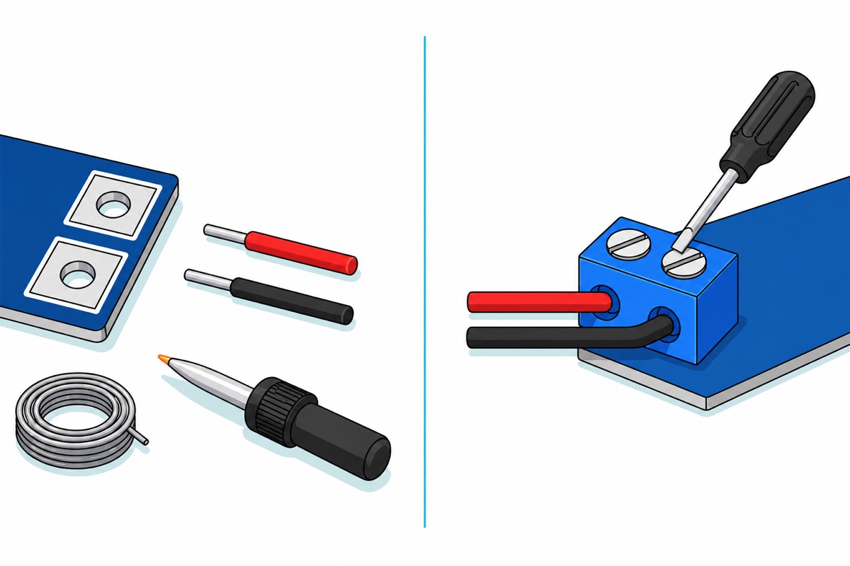
The MT3608, XL6009 and no-display LM2596 arrive with four bare plated holes at the corners — IN+/IN− one end, OUT+/OUT− the other — so you supply and solder the wire yourself; our soldering guide and iron-and-flux basics cover it. The XL4016 instead has blue screw terminals: strip, insert, tighten. On a school deadline that matters more than the price gap.
That choice also sets the order of your bench work. A bare-pad module has nothing to clip a probe onto and nothing to feed it from, so solder short input and output leads on first, power the input, read the output leads with the meter and set the trimmer, and only then join the load.
Two families let you skip the meter altogether: the XL6009 with display and the LM2596 with display carry a three-digit LED voltmeter and an S1 button that toggles the reading between input and output, both on screw terminals. Otherwise an XL830L multimeter and a 12 V 2 A adapter are the bench setup this shelf assumes, and between the four above sit the XL4005 5 A buck and the XL6019 5 A boost. Whatever the connections, adjustment is the same job on all of them — meter on the output, screwdriver on the trimmer, load off:
Common mistakes we see from real customers
Buying a boost for a 12 V adapter and a 5 V load. The most common wrong purchase here, and the trimmer cannot fix it — a boost output cannot go below its input.
Reading the headline current as a promise. On a boost that number is a switch limit in the input path, so a 2 A module fed from a 3.7 V cell and asked for 12 V gives a few hundred milliamps. Size from watts instead: multiply your load’s volts by its amps, divide by 0.85, then divide by your source voltage. That last figure is the current your source must supply and, on a boost, the current the module’s own switch limit has to clear.
Connecting the load before setting the output. These multi-turn trimmers arrive wherever they were left, frequently at 9 V or more. Power the module with nothing on the output, read the output pads with a multimeter, turn the screw, then connect the load — step by step in our LM2596 adjustment guide.
Reversing IN+ and IN−. There is no protection diode on these bare modules, so reversed input polarity destroys them instantly. Check the silkscreen every time.
FAQ
What is the difference between a buck converter and a boost converter?
A buck steps voltage down, a boost steps it up, and the wiring order of switch, inductor and diode fixes that — no adjustment changes it. Source higher than the load, buy a buck; source lower, buy a boost.
Can one module both step up and step down?
Not these four; that needs a buck-boost or SEPIC topology. For a battery whose voltage crosses your target, boost it to a steady 5 V and regulate down from there.
Is a buck converter better than a linear regulator?
For any large drop or real current, yes: a buck moves energy at roughly 85–92% efficiency while a linear burns the difference as heat — 7 W at 12 V to 5 V, 1 A. A linear still wins for tiny drops, small currents and noise-sensitive analogue circuits.
Can I use a voltage divider instead of a buck converter?
No. A divider has no feedback, so its output collapses under load: 12 V through two 1 kΩ resistors reads 6 V unloaded and about 1 V with a 100 Ω load. Dividers scale signals into an analogue input; they never power anything.
LM2596 or XL4016 — which buck should I buy?
The LM2596 up to about 2 A — an Arduino, sensors, a short LED strip. The XL4016 when the load is several amps, because it has the heatsinks, copper and screw terminals for it; note its input starts at 8 V.
Last updated August 2026. Stuck? Chat with us on WhatsApp.

Pingback: 18650 Battery Charger for a 3S Pack: Series vs Parallel
Pingback: NiMH vs Alkaline AA: What Your Project Actually Gets
Pingback: Choose a DC Power Supply: Volts, Amps, Barrel Jacks