

Tutorials
How to Adjust LM2596 Voltage to Exactly 5V (Buck Converter)
Jul
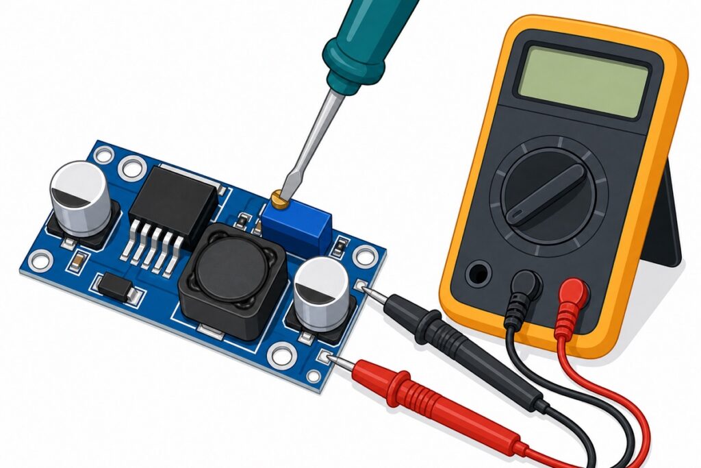
Your LM2596 buck converter ships at a random output — often 9V or 12V — and that is normal, not a defect. To set it to 5V, connect a 7–12V input to IN+/IN−, probe OUT+ and OUT− with a multimeter set to DC volts (the 20V range on manual meters), and slowly turn the trimmer screw until it reads 5.0V — before wiring anything to the output.
Why does my LM2596 read 9V or 12V out of the box?
The little trimmer on the LM2596 module leaves the factory wherever the machine last set it, so the output on arrival is essentially random. We once had a customer ready to return a perfectly working unit because it read 12V — it just had not been adjusted yet.
The LM2596 is a step-down (buck) converter. It takes a higher voltage in and gives a lower voltage out — input roughly 7–35V (some boards tolerate up to 40V absolute maximum), output adjustable from 1.25V to 35V (full chip specs: TI’s LM2596 datasheet). It cannot boost — more on the MT3608 mix-up below.
Parts list
 LM2596S DC-DC Buck Converter Step Down Power Module 4-40V to 1.25-37V Voltage Regulator Board - LM2596S BUCK CONVERTOR
 XL830L Digital Multimeter with backlight Portable Multimeter Electronics Project
 40pcs Dupont Wire 10cm 20cm 30cm for Breadboard DIY Experiment Jumper Wire Breadboard wire - DUPONT WIRE M-F 20CM
Optional upgrades
 LM2596S DC-DC Buck Converter Step Down Power Module 4-40V to 1.25-37V Voltage Regulator Board - LM2596S BUCK CONVERTOR
 5.5x2.1mm DC Power Male Connector Plug Jack Adapter for Arduino DIY Electronics Projects - 5.5x2.1 DC CONNECTOR (M)
The display version shows output voltage without a multimeter.
How do I wire it up before adjusting?
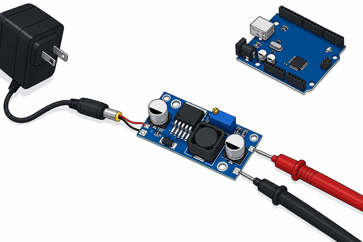
Golden rule: adjust first, connect your circuit after. Feed the input side from a 9V or 12V adapter — a DC jack adapter makes this tidy — and leave the output side completely empty except for your meter probes.
A few jumper wires are handy for temporary connections; if you prefer soldering wires straight to the pads, our guide on how to solder header pins covers the technique.
| Terminal | Connect to | Notes |
|---|---|---|
| IN+ | Adapter positive (e.g., 9V or 12V) | Polarity matters — reversed input can kill the module |
| IN− | Adapter negative / ground | Shared ground with the output side |
| OUT+ | Multimeter red probe only (for now) | Your circuit connects here only after adjustment |
| OUT− | Multimeter black probe only (for now) | — |
One sizing rule before you pick an adapter: the input must be at least about 1.5V higher than the output you want (the dropout). For a 5V output, anything from roughly 7V upward works comfortably — a 9V or 12V adapter is the usual choice.
How do I adjust the LM2596 to exactly 5V?
Step 1 — Power the input, leave the output empty
Connect your adapter to IN+ and IN−, double-checking polarity. Nothing else should be attached to the output yet — a module still set to 12V will cook a 5V circuit.
Step 2 — Set your multimeter to DC 20V
Put your multimeter on the DC voltage 20V range, red probe on OUT+, black probe on OUT−. The display now shows the live output voltage. (On an auto-ranging meter there is no 20V position — just select DC V and the range sets itself.)
Step 3 — Turn the trimmer slowly and watch the meter
The trimmer is a 25-turn multi-turn potentiometer. That means you may turn the screw several full rotations before the voltage even starts to move — this is the point where most people decide the module is broken. It is not. Keep turning.
On the common blue module, anti-clockwise lowers the output, but the direction varies between batches — trust the meter, not the direction. Slow down as you approach 5V and creep onto 5.0V.

Step 4 — Re-check under load
Once it reads 5.0V, connect your actual circuit and measure again at OUT+/OUT−. A small drop under load is normal; nudge the trimmer if you want to compensate. Now you can wire everything permanently.
How much current can it actually deliver?
| Spec | Value | Practical note |
|---|---|---|
| Input voltage | ~7–35V | Up to 40V absolute max on some boards — stay well below |
| Output voltage | 1.25–35V adjustable | Must be ≥ ~1.5V below the input |
| Rated current | 3A max | Treat ~2A as the realistic continuous ceiling |
| Heatsink | Recommended above ~1.5A | The regulator IC runs warm under sustained load |
A typical Arduino or sensor project drawing a few hundred milliamps is fine on the bare module. Past 1.5A continuous — motor drivers, LED strips — add a heatsink and some airflow; Malaysian ambient heat does it no favours.
Can I power an Arduino or ESP32 from the 5V output?
Yes — that is the classic use case. Feed the adjusted 5V into the 5V pin of an Arduino Uno or the VIN/5V pin of an ESP32 dev board (never the 3.3V pin). A quick sanity sketch confirms the rail is doing its job:
// Quick sanity check for your new 5V rail.
// Upload via USB first, then unplug USB and
// power the board from the LM2596 output.
void setup() {
  pinMode(LED_BUILTIN, OUTPUT);
}

void loop() {
  digitalWrite(LED_BUILTIN, HIGH);  // LED on = board is alive on the 5V rail
  delay(500);
  digitalWrite(LED_BUILTIN, LOW);
  delay(500);
}
If the board blinks happily on USB but your ESP32 refuses to show up for uploading, that is a separate problem — see our ESP32 not detected fix. And once you have a solid 5V rail, projects like the jemuran automatik with rain sensor become straightforward builds.
LM2596 vs MT3608 — did you buy the right one?
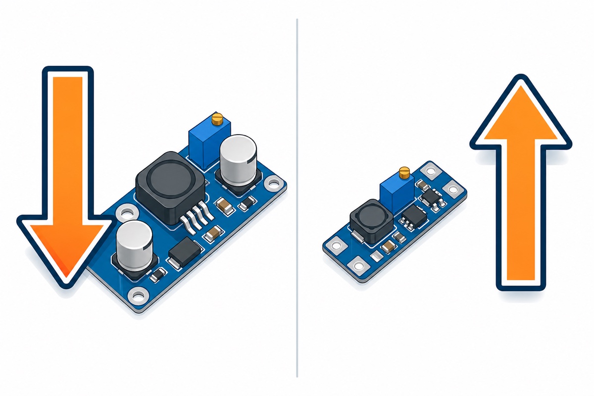
This mix-up causes real returns. The two modules look similar but do opposite jobs:
| Module | Type | Direction | Example use |
|---|---|---|---|
| LM2596 | Buck (step-DOWN) | Output is LOWER than input | 12V adapter → 5V for Arduino |
| MT3608 | Boost (step-UP) | Output is HIGHER than input | 3.7V battery → 5V for USB gadget |
If your source voltage is higher than what you need, buy the LM2596; if it is lower, you need a boost module. An LM2596 can never turn 3.7V into 5V.
Common mistakes we see from real customers
“Saya baru lepas beli boost ni. Macam mana adjust ke 5V ya? First time guna” — small but important correction: the LM2596 is a buck (step-down), not a boost. The adjustment itself is exactly the steps above — power the input, probe the output, turn the trimmer to 5.0V. But if your input is lower than 5V, this module cannot get you there.
“ini bukannya 5v bos, ini 9v atau 12v… macam mana saya nak pulangkan benda ni?” — no return needed. Every unit ships at a random factory setting, often 9–12V. That reading proves the module works; two minutes with a screwdriver and a multimeter brings it to 5V.
“untuk bacaan macam mana?” — set the multimeter dial to DC voltage (the V with a straight line, 20V range), red probe on OUT+, black on OUT−. The number on the screen is your output voltage. If reading a meter feels like a chore, the LM2596 with built-in display shows the output voltage right on the module.
One more we see on arrival day: input wires swapped. Reversed polarity on IN+/IN− can kill the module instantly, so double-check red-to-plus before powering up.
FAQ
I keep turning the screw but the voltage does not change. Is it broken?
Almost certainly not. The trimmer is a 25-turn pot, so many full rotations can pass before the output starts moving. Keep turning while watching the meter.
Which direction lowers the voltage?
Anti-clockwise on the common blue module, but the direction varies between boards. Watch the multimeter, not the screw — the reading tells you instantly which way you are going.
What input voltage should I use for a 5V output?
Anything at least ~1.5V above the target, so roughly 7V and up. A common 9V or 12V adapter is ideal, and the module accepts up to about 35V.
Can the LM2596 increase voltage, like 3.7V to 5V?
No. It only steps down. For stepping up you need a boost converter such as the MT3608 — the opposite type of module.
How many amps can I draw at 5V?
It is rated 3A max, but plan around ~2A continuous in practice, and add a heatsink once you are drawing above ~1.5A for sustained periods.
Last updated July 2026. Stuck? Chat with us on WhatsApp.
