

Tutorials
How to Test a Capacitor With a Multimeter
Aug
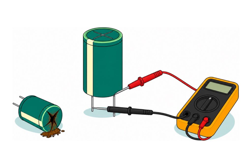
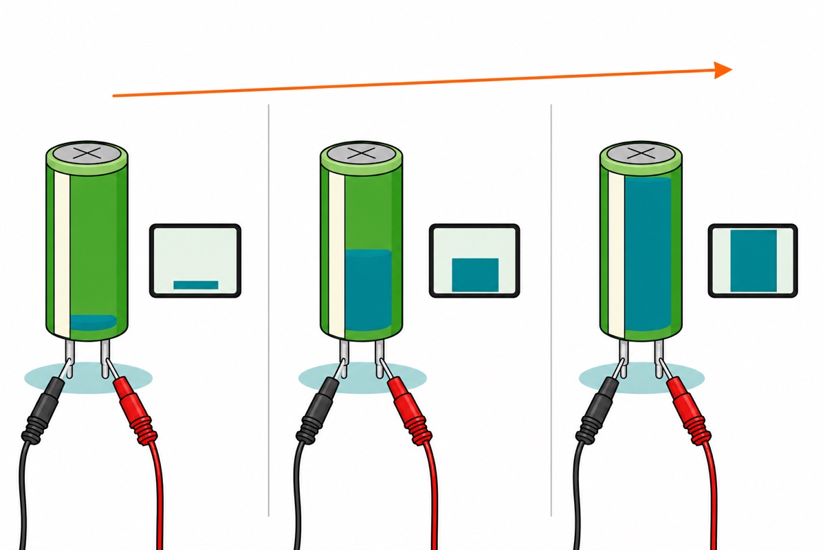
Discharge the capacitor, set the meter to its highest ohms range, then put the red probe on the positive leg and black on the negative. A healthy capacitor makes the reading climb steadily and finish at OL — the over-range reading; a shorted one sits near zero; an open one shows OL instantly with no climb. The capacitance value is not something a basic meter reads — that number is printed on the part.
The XL830L we sell has DC volts, AC volts, DC current, five ohms ranges and a combined diode-and-continuity position, but no farad range. What it gives you instead is the verdict — good, open, shorted or leaky — which is what you want when a board dies or a supply browns out.
Everything here is low-voltage DC bench work, out of circuit. Mains equipment is a different job — see the discharge section below.
How do you read a capacitor’s value when the meter cannot?
A capacitor’s value is printed on it. Electrolytics — the tall cans, including the green-sleeved radials in our starter kit — have room for it in full, such as 100 µF 50 V. That voltage is a ceiling, not a target: the most DC the part may ever see.
Small ceramic discs have no room, so they use a three-digit code: two significant figures, then that many zeros, in picofarads. So 104 means 10 followed by four zeros — 100,000 pF, which is 100 nF, which is 0.1 µF.
| What is printed | How to read it | Worked example |
|---|---|---|
| A µF figure and a voltage on a can | Capacitance, then the maximum DC across it | 100 µF 50 V — 100 microfarads, never above 50 V DC |
| Pale stripe down one side of the can | The leg on the stripe side is negative | Black probe goes to that leg |
| One leg longer than the other, untrimmed | The long leg is positive | Red probe goes to that leg |
| Three digits on a small disc | Two figures, then that many zeros, in picofarads | 104 → 10 + 0000 = 100,000 pF = 0.1 µF |
| One or two digits on a small disc | Already picofarads | 22 → 22 pF |
| Letter after the digits | Tolerance | J = ±5%, K = ±10%, M = ±20% |
Parts list — the meter, and a box of capacitors to practise on
 XL830L Digital Multimeter with backlight Portable Multimeter Electronics Project
 Electronic Component Set Beginner Electrical Learning Kit For Arduino Beginner Learning - ELECTRICAL STARTER KIT
Optional — makes the test easier to hold and safer to set up
 Crocodile Clip Cables 46cm Alligator Clip Cable Multi Color
 400 pcs 1/4W Resistor Pack Resistor Kit 20 Common Value with 20 each
 MB102 Breadboard 170 400 830 Holes Breadboard Donut Board Arduino Prototype Multi Color - BREADBOARD (400 HOLES)
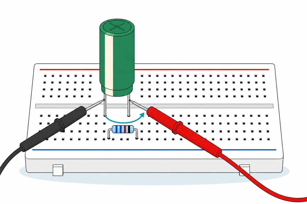
Crocodile clip leads hold a capacitor's legs against the probes so you can watch the display instead of your hands. The resistor pack is only needed if you skip the starter kit — you want a 1 kΩ 1/4 W resistor as your discharge bleeder. The 400-hole breadboard grips the capacitor and the resistor together while it drains.
New to the dial? Our guide to using a digital multimeter covers the ranges and jacks first.
How do you discharge a capacitor safely before touching it?
A charged capacitor holds ½ × C × V² of energy: a 1000 µF capacitor at 12 V holds about 0.072 joules. How fast it comes out is decided entirely by what you put across it.
Bridge the legs with a screwdriver and the path resistance is effectively nothing, so the only limit on the current is the capacitor’s own internal resistance: the whole charge leaves in microseconds at tens or hundreds of amps. That is the bang and the spark, and it pits the tip and stresses the internal foil tabs.
Put a 1 kΩ quarter-watt resistor across the same legs instead and every number becomes tame. Starting current is 12 V ÷ 1000 Ω = 12 mA. The time constant is R × C = 1000 Ω × 0.001 F = 1 second, so after five time constants the capacitor is below one percent of where it started. The worst instant the resistor sees is V² ÷ R = (12 V × 12 V) ÷ 1000 Ω = 0.144 W — inside a quarter-watt part, and falling from the moment it starts. Any value from a few hundred ohms to a few kilohms does the same job, as long as those two sums stay inside the resistor’s own rating. A 400-hole breadboard holds both in the same pair of columns while it drains.
Then prove it. Switch to DC volts on the 2 V range and read across the legs: under 1 V before your fingers go near, ideally under 0.1 V. Assuming five seconds was enough is not the same as checking.
Mains equipment is out of scope, and not as a formality. A 220 µF bulk capacitor inside a mains supply sits at around 400 V, and the same formula gives 17.6 joules — roughly 240 times the bench example above, still there days after the plug came out. Motor-run and ceiling-fan capacitors hold less energy than that but sit at hundreds of volts on the mains rail and bite just as hard, and those jobs need equipment and training this article does not give you.
The bleeder-resistor arithmetic, worked through on the bench:
What is the test, step by step?
The XL830L needs its leads in the right two jacks before anything else: black in COM, red in VΩmA. The third jack, 10ADC, is a current input — a near-zero-ohm path straight through the meter — and the panel beside it prints 10A MAX UNFUSED. A red lead left in there and laid across a charged capacitor is a dead short with nothing to interrupt it.
- Kill the power and unplug the board. The ohms range works by pushing its own tiny current through the part and reading the voltage that results; any voltage still alive in the circuit swamps that current and the number means nothing.
- Discharge it where it sits — the 1 kΩ resistor straight across the capacitor’s own two legs — then read across those same legs on DC volts and confirm you are under 1 V.
- Free one leg. Desolder it and lift it clear of its pad, so nothing else on the board is sitting in parallel with the part you are about to measure.
- Dial to 2M to start, red probe on the leg away from the stripe, black probe on the striped leg. Ceramic discs have no stripe and no polarity — either way round is fine.
- Watch the display for several seconds, not for an instant. A pass is a number that climbs and then goes over-range — OL on some meters, a lone 1 with the other digits blank on others. The verdict table below reads the three failures.
- Discharge it again before your fingers, or a second test, go anywhere near it.
Why does the ohms range make a good capacitor climb?
The XL830L’s ohms range pushes a small known current out of the red probe, through whatever lies between the probes and back into COM, then displays the resulting voltage scaled into ohms. Across a resistor that voltage is fixed by V = I × R, so the number sits still.
A capacitor has no fixed voltage for a given current. The current pours charge in, the charge accumulates as Q = I × t, and the voltage is that charge divided by the capacitance: V = I × t ÷ C. So the voltage rises steadily with time and the displayed “resistance” rises with it, until the capacitor’s voltage matches what the meter can supply, current stops, and the display reads OL. That climb is not the meter measuring resistance — it is you watching a capacitor charge. The meter runs on a 9 V battery, but the ohms source sits well below it: the XL830L’s manual specifies a maximum open-circuit voltage of 3.2 V on every resistance range, so the test can never take a capacitor past 3.2 V. Harmless to the part — and still enough charge left in it to spoil your next reading.
The rate of the climb is I ÷ C, which sets the one honest limit of this test. Ten times the capacitance means one tenth the climb rate, so a 0.1 µF ceramic finishes a thousand times faster than a 100 µF electrolytic — and the display refreshes only two or three times a second. Below roughly 0.1 µF you will see OL and nothing else, and between 0.1 and 1 µF only a second or so of climb before it settles. Use the 2M position to begin with, because the reading has to walk the whole range before it reads OL: the run lasts roughly the range’s full-scale resistance multiplied by the capacitance, so a 1 µF part takes about a second on 2M and would flash past on any lower range.
The same arithmetic cuts the other way for a fat 100 µF electrolytic, which needs a minute or more to reach OL on 2M — judge that one on the steady climb instead of waiting it out, or drop to the 20k or 200k position and watch the whole run in seconds. Treat the range as the length of the run and let the display choose it for you: step down when the climb is too slow to see it finish, step back up when the reading is over before your eyes have settled.
| What the display does | What is happening inside | Verdict |
|---|---|---|
| Starts low, climbs steadily, settles at OL | Test current is filling the capacitor until its voltage matches the meter’s | Good |
| Jumps straight to OL, no climb at all | Charge is going nowhere — an internal connection or the foil is broken | Open — unless the printed value is a fraction of a microfarad, or the range is too low for it. Step up a range and look again before condemning it |
| Sits near zero and stays there; switch to the continuity position and the buzzer sounds without letting up | The dielectric has punctured, so the two plates are joined | Shorted — but let the buzzer decide: a big electrolytic on the 2M range creeps so slowly that a healthy one can look motionless too |
| Climbs, then stops at a steady number well below OL | A fault path through the dielectric is bleeding away exactly as much current as the meter supplies, so the voltage stops rising | Leaky — and the number it settles on is that path’s resistance. A healthy electrolytic offers nothing the 2M range can even see |
On a digital meter the red probe is the positive one in ohms mode, the opposite of many old analogue meters — and you can prove it on yours in ten seconds. Charge a large electrolytic on the 2M range with red on the leg away from the stripe, then turn the dial to DC volts without moving either probe. A positive reading means red was positive.
Discharge again before repeating the test — the capacitor came away from the first run holding a charge the meter put there. Crocodile clip leads make the sequence one-handed, and our guide to clip leads covers getting a grip that does not slip mid-climb.
The resistance method demonstrated on a real display:
Why do capacitors fail, and what do bulges and leaks mean?
An aluminium electrolytic capacitor gets its value from C = ε × A ÷ d, where A is plate area and d the gap between the plates. Its plates are a long strip of foil rolled into the can, giving a large A; its insulator is an oxide film grown electrochemically on that foil, a fraction of a micrometre thick, giving a tiny d. Huge area over a hair-thin gap is why a fingertip-sized can holds hundreds of microfarads — and why every common failure happens.
That oxide film is only maintained by DC applied in one direction. Reverse the polarity and the film is stripped away, current flows through the wet electrolyte, gas forms, pressure builds, and the scored cross on the top face opens as the pressure vent it was designed to be. Exceed the rated voltage and the sub-micron film punctures directly — that is the short. And because the electrolyte is a liquid behind a rubber bung, it escapes as vapour over the years, faster the hotter it runs; less electrolyte means less working plate area, so capacitance falls and internal resistance rises. That is dry-out, the ordinary way capacitors die of old age, and heat sets its pace: manufacturers reckon life roughly halves for every 10 °C rise, so a part good for ten years in a cool box lasts about two and a half at 20 °C hotter.
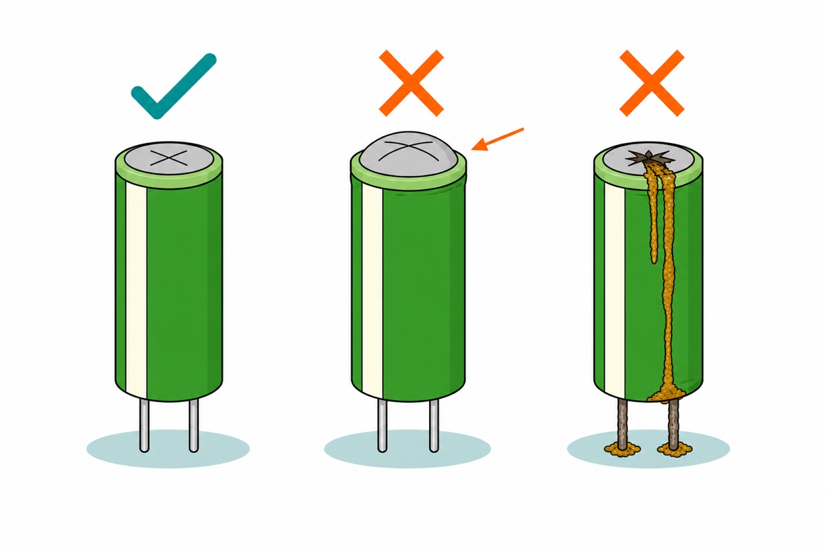
All of that is visible before you reach for the meter. A domed or split top, brown crusty residue at the vent or base, a can standing proud of the board, corroded legs — any one means replace it. The trap runs the other way: dry-out looks immaculate, so a capacitor that has quietly lost half its value presents as a fault somewhere else — a browning-out SIM800L, or a noisy LM2596 rail.
Common mistakes we see
Testing the capacitor while it is still soldered in. Everything else on the board sits in parallel with it, so the meter reads that path, not the part. Lift one leg first.
Repeating the test without discharging in between. The second run reads OL from the first instant — the commonest way a healthy capacitor gets thrown away as open.
Reading the stripe as the positive side. On an aluminium electrolytic the stripe marks the negative leg — the opposite of a tantalum capacitor, where the bar marks positive, which is where the habit comes from.
Treating a pass as proof of the value. A capacitor dried out to half its printed microfarads still charges, climbs and ends at OL. When the value is what you doubt, substitute a known-good part.
Fitting the replacement the wrong way round. The striped leg goes to the shaded or minus-marked half of the outline printed on the board. Backwards, the mechanism above starts running from the first second of power — the oxide film strips, gas forms, and the vent opens on a brand-new part.
FAQ
Can I test a capacitor with a multimeter that has no capacitance setting?
Yes, for the failures that matter. The ohms range shows a good capacitor charging — climbing to OL — while a shorted one stays near zero and an open one never climbs. It cannot measure microfarads; read those off the printing.
Which multimeter lead is positive on the ohms range?
The red probe, with current returning through COM — the reverse of many old analogue meters. Prove it on yours by charging an electrolytic on the 2M range, then switching to DC volts without moving either probe: a positive reading confirms red was positive.
Why does my small ceramic capacitor read OL straight away on the ohms range?
Because it is doing what it should. The climb rate is the test current divided by the capacitance, so a 0.1 µF part finishes a thousand times faster than a 100 µF one — long before the display refreshes. Below roughly 0.1 µF the test only proves the part is not shorted.
Do I have to remove a capacitor from the circuit board to test it?
At least one leg. In circuit, the test current takes every parallel path on the board too, so a low reading may be a coil winding or a resistor rather than a faulty capacitor. Desolder one leg, test, resolder.
My capacitor is bulging at the top — can I still use it?
No. A domed top means internal pressure has already pushed the scored vent outward, so gas has formed and the electrolyte is compromised. It can still charge, climb and read OL while being unfit for the circuit. Replace it — same microfarad value, same or higher voltage rating.
Last updated August 2026. Stuck? Chat with us on WhatsApp.
