

Tutorials
HX711 Load Cell Arduino: Build a 5kg Weighing Scale
May
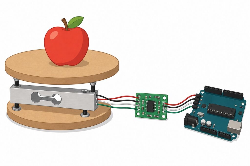
To build a weighing scale you need four parts: an Arduino Uno, a 5kg bar load cell, an HX711 amplifier module and two mounting plates. The load cell measures weight by bending — fix one end to the base plate, hang the platform on the other end, and the HX711 converts that tiny flex into grams on your Arduino.
How does a bar load cell actually measure weight?
The 5kg bar load cell is a solid aluminium bar with strain gauges hidden under the white protective sticker. Hold one end fixed, hang a weight on the other, and the bar bends by a hair — the gauges change resistance by an amount far too small for an Arduino pin to read directly. That is where the amplifier comes in.
The HX711 module is a 24-bit ADC designed specifically for weigh scales: channel A amplifies the load cell signal with a gain of 128 or 64, it outputs 10 or 80 samples per second depending on the module’s RATE solder pad (boards like this one ship set to 10 — plenty for a scale), and it runs from 2.6–5.5V, so the Uno’s 5V pin powers everything.
Parts list
 Arduino Uno Compatible SMD UNO R3 with Type B Cable - ATMEGA328P with CH340G-Microcontroller Project
 HX711 Load Cell Weight Sensor Module Digital Scale Kit 1kg 5kg 10kg 20kg Amplifier ADC Arduino DIY - 5KG LOAD CELL BAR
 HX711 Load Cell Weight Sensor Module Digital Scale Kit 1kg 5kg 10kg 20kg Amplifier ADC Arduino DIY - HX711AD MODULE
 HX711 Load Cell Weight Sensor Module Digital Scale Kit 1kg 5kg 10kg 20kg Amplifier ADC Arduino DIY - WEIGHT SENSOR PLATE
How do you mount the load cell so it reads correctly?
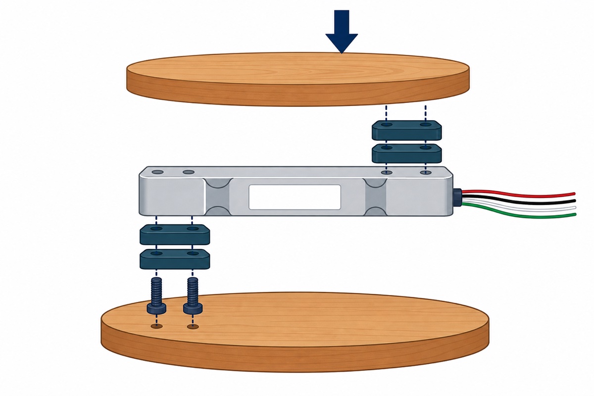
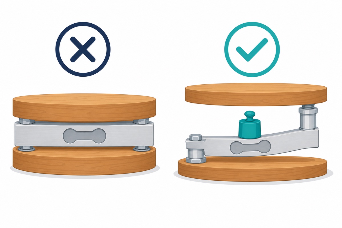
The weight sensor plate kit exists because mounting — not wiring, not code — is where most weighing scale builds go wrong. A bar load cell only works if it is free to bend. That means a specific sandwich: the bottom plate bolts to one end of the bar, the top platform bolts to the other end, and the small spacers in the kit lift the bar away from both plates so there is a visible flex gap above and below it.
Three rules make or break the build:
- One end per plate. The base holds one end, the platform hangs on the opposite end. Bolt both ends rigidly and the bar cannot bend — the reading barely moves whatever you put on top.
- Keep the flex gap. Fit the spacers between the bar and each plate. A bar sitting flat against a plate bottoms out, so readings get stuck or read low.
- Respect the load direction. If your bar carries a printed arrow, it points in the direction the load pushes (downwards, from the platform side). Loading the wrong face or wrong end gives wrong or even negative numbers.
Each end of the bar has two threaded holes — use the kit’s countersunk screws in the pair nearest each end, spacer between plate and bar.
How do you wire the load cell to the HX711 and Arduino Uno?
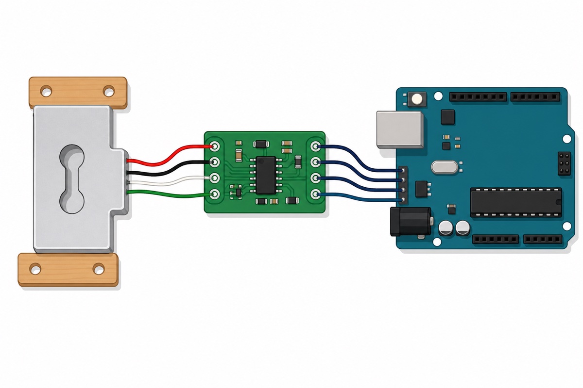
The green XFW-HX711 board has the load cell terminals on one edge and the Arduino pins on the other. On these bar cells the usual convention is red = excitation+, black = excitation−, white = signal−, green = signal+ — but colour codes vary between batches, so treat the table below as the starting point, not gospel. Leave B− and B+ empty — this build only uses channel A (channel B has a fixed, lower gain of 32).
| Load cell wire | HX711 terminal | Meaning |
|---|---|---|
| Red | E+ | Excitation + (bridge power) |
| Black | E− | Excitation − |
| White | A− | Signal − (channel A) |
| Green | A+ | Signal + (channel A) |
| HX711 pin | Arduino Uno pin | Notes |
|---|---|---|
| VCC | 5V | Accepts 2.6–5.5V; the Uno’s 5V is fine. |
| GND | GND | Common ground. |
| DT (DOUT) | D2 | Data out; any digital pin works. |
| SCK | D3 | Clock; any digital pin works. |
Two practical notes. First, the HX711AG ships with its header strip loose in the bag — solder it (or solder the wires directly) before trusting any reading, because loose pins are the number one cause of jumpy numbers; our how to solder header pins guide covers it. Second, if your wire colours differ, find the pairs with a multimeter: each true pair (excitation, signal) measures roughly the full bridge resistance, while any mixed combination reads about three-quarters of that. Of the two true pairs, the one with the slightly higher reading is the excitation pair (E+/E−) and the lower one is the signal pair (A+/A−) — on this family of bars the input side reads around 1115Ω against roughly 1000Ω on the output side — our digital multimeter guide shows the resistance check. There is also a higher-precision HX711 variant for finer measurements.
How do you calibrate the scale with a known weight?
The HX711 outputs raw counts, not grams — calibration is simply finding the number that converts one into the other. Install the library first: in the Arduino IDE open Sketch → Include Library → Manage Libraries and search for HX711 Arduino Library by Bogdan Necula. Then upload this calibration sketch:
#include "HX711.h"

const int LOADCELL_DOUT_PIN = 2;
const int LOADCELL_SCK_PIN = 3;

HX711 scale;

void setup() {
  Serial.begin(57600);
  scale.begin(LOADCELL_DOUT_PIN, LOADCELL_SCK_PIN);
  Serial.println("Remove all weight. Taring in 3 seconds...");
  delay(3000);
  scale.tare();  // set the current (empty) reading as zero
  Serial.println("Done. Now place your known weight on the platform.");
}

void loop() {
  // Average of 10 readings with the tare offset already removed
  long raw = scale.get_value(10);
  Serial.print("Raw value: ");
  Serial.println(raw);
  delay(1000);
}
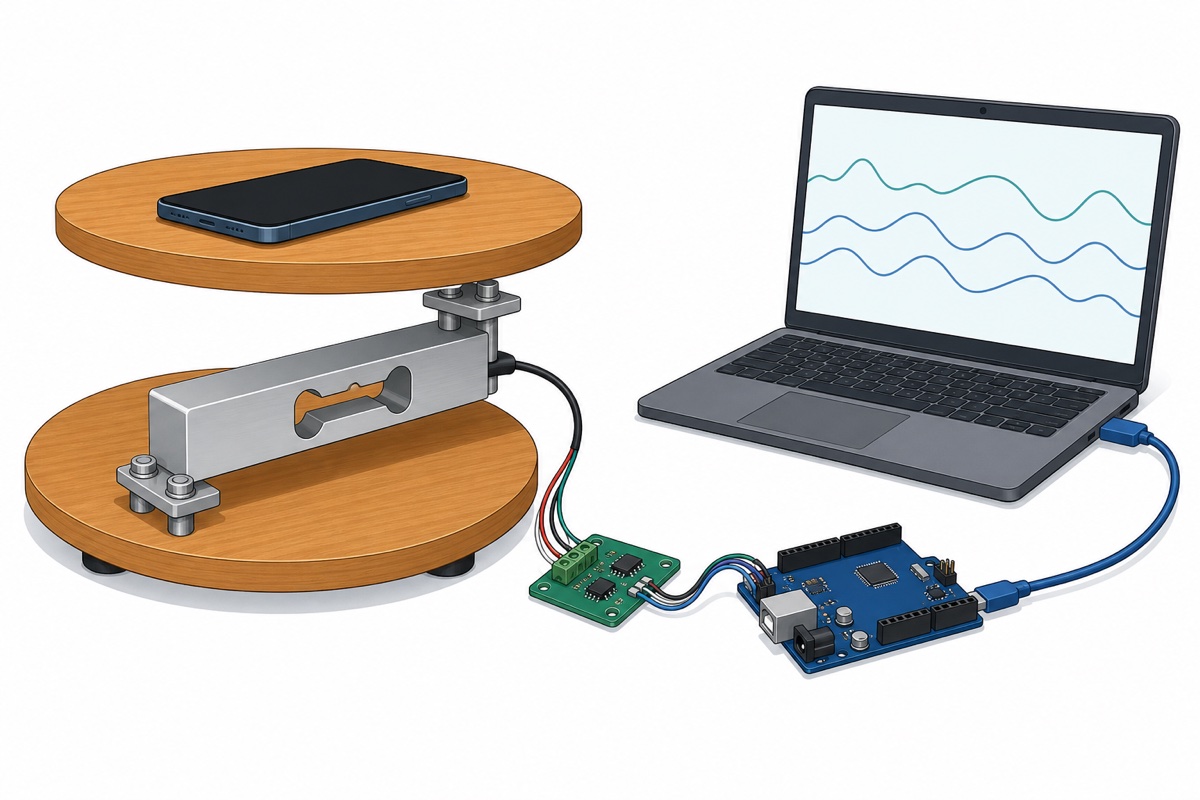
With nothing on the platform the sketch tares (zeroes) itself. Now place a weight you genuinely know: a phone with a published spec weight works well, or an unopened packaged food item (the printed figure is net weight, so the packet weighs slightly more). The maths is one line:
CALIBRATION_FACTOR = raw value ÷ known weight in grams. If the serial monitor shows about 84,000 with a 200g weight on the platform, your factor is about 420. A negative raw value means your cell or wiring is reversed — keep the minus sign in the factor and the final scale will read positive.
What is the full Arduino code for the weighing scale?
The final HX711 sketch below is the calibration sketch’s big brother: paste your factor into CALIBRATION_FACTOR, upload, and the serial monitor becomes your scale display. Want a proper screen later? The LCD1602 I2C wiring in our Arduino digital clock tutorial drops straight into this project.
#include "HX711.h"

const int LOADCELL_DOUT_PIN = 2;
const int LOADCELL_SCK_PIN = 3;

// Replace with the number from YOUR calibration run
const float CALIBRATION_FACTOR = 420.0;

HX711 scale;

void setup() {
  Serial.begin(57600);
  scale.begin(LOADCELL_DOUT_PIN, LOADCELL_SCK_PIN);
  scale.set_scale(CALIBRATION_FACTOR);
  Serial.println("Remove all weight. Taring in 3 seconds...");
  delay(3000);
  scale.tare();
  Serial.println("Scale ready.");
}

void loop() {
  if (scale.is_ready()) {
    // Average of 10 readings, converted to grams
    float grams = scale.get_units(10);
    Serial.print("Weight: ");
    Serial.print(grams, 1);
    Serial.println(" g");
  } else {
    Serial.println("HX711 not found - check DT/SCK wiring");
  }
  delay(500);
}
Expect the last gram or two to wander — hobby-grade bar cells drift a little with temperature and creep slightly under sustained load. Re-tare at the start of each session for the most consistent numbers. Wildly jumping readings are almost never the HX711 chip: they are loose header pins, a swapped wire pair, or a mounting problem from the section above.
One of the most common requests in our chat is “load cell + HX711 install tutorial video please” — this walkthrough covers the four-wire hookup, mounting and calibration end to end (its code section uses a different HX711 library — follow the sketches on this page instead):
Common mistakes we see from real customers
The same few problems account for nearly every load cell and HX711 install question in our support chat.
- Bolting the bar rigid at both ends. The scale powers up, tares, then barely responds to weight. The bar must be free to bend — one end on the base, the other on the platform, flex gap in between.
- Skipping the spacers. The bar rests flat on the plate and bottoms out, so readings stick long before 5kg. The spacers in the plate kit are not packaging — they are the mechanism.
- Trusting the wire colours blindly. A swapped white/green pair gives negative or mirror-image readings. Swap the pair at A+ and A−, or keep the negative calibration factor.
- Using the HX711 with unsoldered headers. Pins resting in breadboard holes produce exactly the jumpy readings people then blame on the chip.
- Calibrating against a guessed weight. The scale then reads consistently — and consistently wrong. Use a phone with a published spec weight or another verified reference.
FAQ
Why are my readings negative?
Either the signal pair is swapped (white and green reversed at A+ and A−) or the load cell is mounted so the load bends it the opposite way to its arrow. Swap the two signal wires, flip the mounting, or simply use a negative calibration factor — all three give the same correct result.
Why does the reading drift after a few minutes?
Hobby-grade bar load cells drift slightly with temperature changes and creep slightly under sustained load — that is normal at this price point, not a fault. Tare before each weighing session and avoid leaving weight sitting on the platform for hours if you need repeatable numbers.
Can I weigh more than 5kg on this load cell?
No — past its rating the bar can bend permanently, and after that it never reads correctly again. If you expect heavier loads, use the 10kg or 20kg version of the same bar (available on the same product page) and keep a safety margin below the maximum.
Do I really need to solder the HX711 header pins?
Yes. The header strip ships unsoldered in the bag, and pins resting loose in the holes make intermittent contact that shows up as jumping or frozen readings. Ten minutes with a soldering iron fixes it permanently.
Can I add an LCD display instead of the serial monitor?
Yes — an LCD1602 with an I2C backpack needs only four wires (5V, GND, A4, A5) and leaves D2 and D3 free for the HX711. Get the scale working on the serial monitor first, then move the print statements to the LCD.
Last updated August 2026. Stuck? Chat with us on WhatsApp.
