

Tutorials
Ultrasonic Mist Maker Module: Build a DIY Humidifier That Runs
Aug
An ultrasonic mist maker is a piezo-driven metal plate full of micro-holes, and the water it atomises is also its only coolant — so a plate driven dry degrades within seconds to minutes. That one fact decides the build: give the module its own 5 V supply, switch that supply with a relay or a MOSFET rather than from a microcontroller pin, and let a water-level sensor cut it before the tank empties.
Everything here is 5 V DC from a USB charger. Nothing goes near mains.
How does an ultrasonic mist maker actually work?
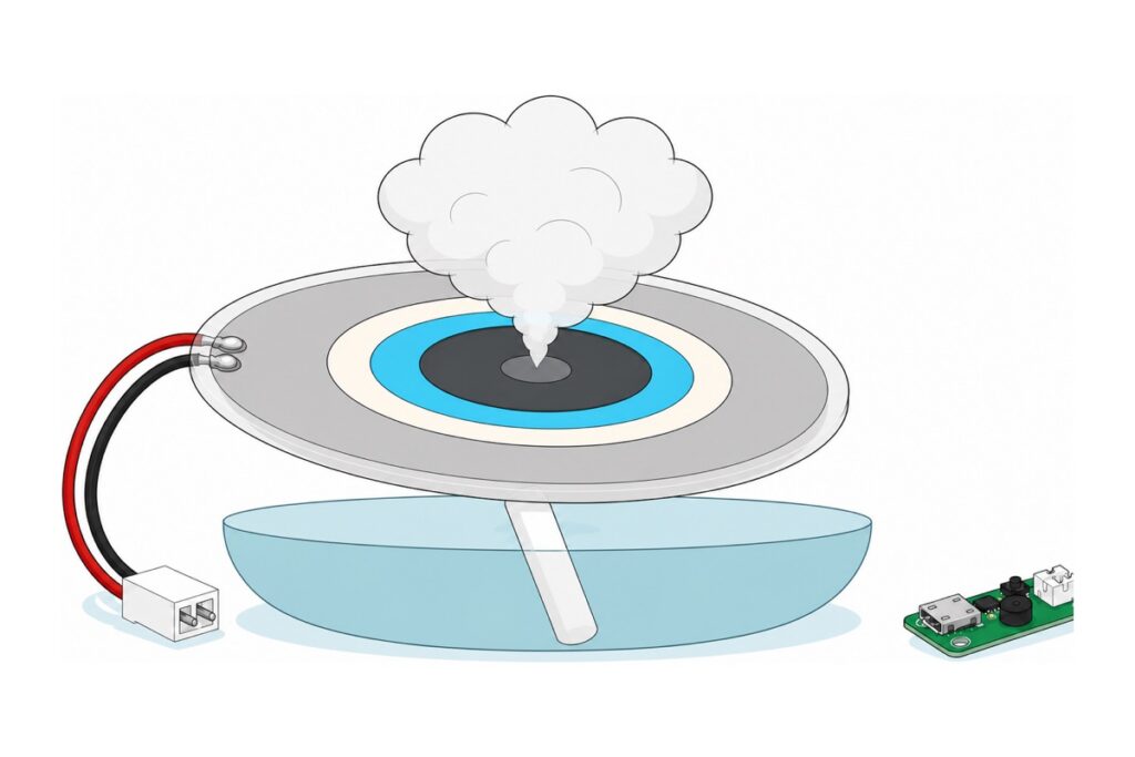
Sold as an ultrasonic mist maker, an ultrasonic atomizer module, a fogger module or a mist generator, it is always the same two parts: a driver board and a transducer. The transducer in the ultrasonic mist maker kit is not a solid disc: the dark grey dot inside the sky-blue ceramic ring is a thin metal plate perforated with roughly 740 tapered holes, wide on the water side and a few microns across on the air side.
The blue ring is the piezoelectric part. Feed it 108 kHz alternating voltage and it expands and contracts in its own plane; clamped around the rim of the stiffer perforated plate, that in-plane strain is forced to become out-of-plane flexing, so the centre of the plate pistons back and forth by a fraction of a micron, 108,000 times a second. Each cone-shaped hole fills from the wetted face on the backstroke and fires that slug out of the narrow end on the forward stroke, where it breaks into droplets of about 5 µm. This is a pump, not the cavitation a solid-disc tank fogger uses — and droplets that small evaporate before they can fall, which is why the plume reads as dry fog. Published work on vibrating-mesh atomisers drove plates of this kind at fixed frequencies right across the 100–300 kHz range.
The small green driver board does the electrical half: a fixed-frequency oscillator that bangs out roughly 108 kHz at the plate open-loop, with no feedback from it at all, so there is no waveform for you to generate — and it starts the moment 5 V arrives. That is the fact the control scheme rests on: the black button cycles drive modes while power is applied, but cutting the 5 V and restoring it brings the board up in its power-on state, so a relay in the supply is a whole on/off control rather than half of one. Good practice before wiring anything: wet the wick, plug the module into a phone charger, and confirm it mists with no button press.
A bench teardown of this class of atomiser board, with the schematic drawn out:
Parts list — the zero-solder build
 Humidifier Module Atomization Board Ultrasonic Mist Maker Fogger Transducer Ceramic Plate DIY Project Parts
 Arduino Uno Compatible SMD UNO R3 with Type B Cable - ATMEGA328P with CH340G-Microcontroller Project
 Relay Module 3.3V 5V 12V 1/2/4/8 Ways Optocoupler Trigger Relay Module 1 2 4 8 Channel Relay Module - 5V RELAY MODULE(1WAY)
 Water Level Sensor Water Level Detector Module For Arduino IOT Application
 Data Cable Type-A Type-C MicroUSB Type-B 0.5m 1m 30cm 0.3m 100cm Data Transfer Upload Code - MicroUSB CABLE (1.0M)
 40pcs Dupont Wire 10cm 20cm 30cm for Breadboard DIY Experiment Jumper Wire Breadboard wire - DUPONT WIRE M-F 20CM
 40pcs Dupont Wire 10cm 20cm 30cm for Breadboard DIY Experiment Jumper Wire Breadboard wire - DUPONT WIRE M-M 20CM
Optional — a different switch, a different brain, a programming cable
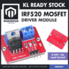 IRF520 MOSFET Driver Module PWM Output Power Control for Arduino Raspberry Pi DC Motor Control
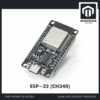 NodeMCU ESP32 Wi-Fi + Bluetooth Development Board CH340/CP2012 - For IOT Project - ESP-32 (CH340)
 Data Cable Type-A Type-C MicroUSB Type-B 0.5m 1m 30cm 0.3m 100cm Data Transfer Upload Code - TYPE-A TO TYPE-B (1.0M)
The IRF520 MOSFET module switches silently with no contacts to wear, but it interrupts the negative side rather than the positive and its gate is not logic-level — read our IRF520 guide before swapping it in. The ESP32 board is the upgrade if you want schedules or a web page instead of a fixed threshold; the same relay works from its 3.3 V pins in the low-trigger jumper position — but low trigger inverts the resting state, so pick a GPIO that is not held low at boot and drive it high in the first line of setup(). The A-to-B cable fits the Uno's Type-B port.
The mist maker box holds four pieces, not a bare board: the green driver PCB, the 20 mm transducer already soldered to a lead ending in a white JST plug, a cotton wick stick, and two black housing halves. The wick slides into the tube of the lower half and the disc drops face-up into the cap, so pushing the cap on rests the disc’s underside on the wick — that contact is the entire water path. The plug then goes into the driver board’s white socket, which mates one way round only.
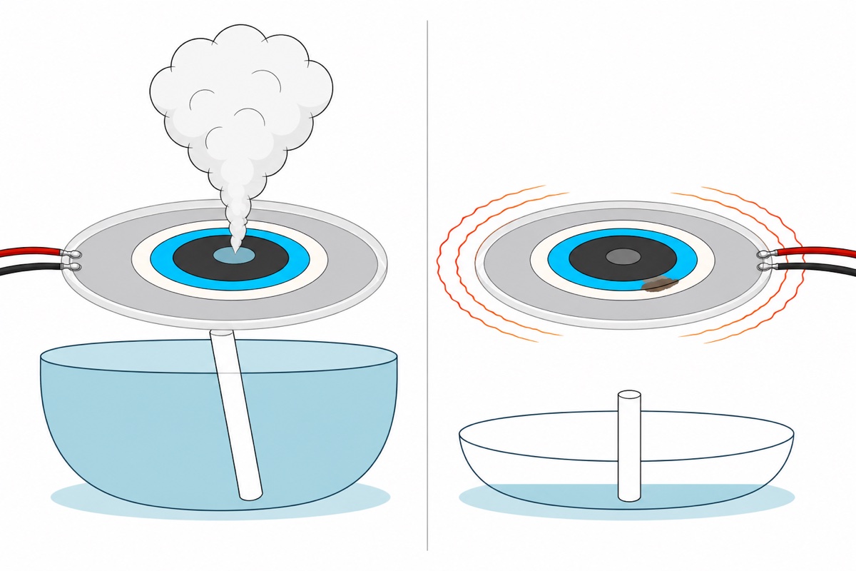
Why does the plate die in seconds if it runs dry?
Water on a mist maker’s plate is doing three jobs at once: it is the working fluid, it is the mechanical load, and it is the only heatsink the ceramic has.
Take it away and all three go together. Every droplet thrown carries energy out with it, and the surface film damps the plate’s motion; unloaded, the same drive produces a much larger swing with nothing to spend the energy on. It becomes heat instead, in a ceramic ring a few tenths of a millimetre thick whose cooling path is the water that is no longer there.
The damage is permanent rather than a fault you can reset. Piezoelectric ceramic works because its internal domains were aligned once, at the factory, by a strong field; heat scrambles that alignment and the material depolarises, and it does not repolarise on cooling. A cooked plate can still look perfect and still draw current — it simply makes less mist, or none.
Nothing on the driver board is watching for this. Its oscillator runs open-loop, with no feedback from the plate at all, so it cannot tell a flooded disc from a bone-dry one — it keeps driving either. The only dry-running measure the driver-board documentation for this class describes is a timed auto-shutdown after four or eight hours, and a clock is not a water sensor. The case that matters is a partly wet plate: a wick that has stopped reaching water leaves a film over some holes and nothing over the rest, so the mist thins but never stops, and the dry area cooks while the board carries on.
How much current does the module draw, and why can a pin not supply it?
The mist module is rated 5 V, 300 mA and 2 W in that same class documentation, and those three figures do not quite agree with one another: 300 mA at 5 V is 1.5 W, while 2 W ÷ 5 V = 0.4 A. Design for the larger of the two and you are covered either way, so budget 0.4 A.
An Arduino Uno‘s I/O pin is specified for 20 mA as its recommended figure. Four hundred milliamps is twenty times that, so this is not a marginal call — the pin’s output transistor would be asked to behave like a piece of wire, and it fails short or open, usually permanently.
The Uno’s own 5 V rail is not the answer either. A USB 2.0 port hands the whole board 500 mA, and the microcontroller, the USB-serial chip and the relay coil are already spending it, so a 0.4 A load leaves barely a hundred milliamps for everything else. Push past it and the port’s own overcurrent protection cuts the rail — which takes the Uno down together with the mist, and your dry-run guard with it.
| Load | Current it needs | Where it may be powered from |
|---|---|---|
| Mist maker module | Rated 300 mA; budget 0.4 A (2 W ÷ 5 V) | Its own 5 V USB charger rated 1 A or better, switched |
| Relay coil (Songle SRD-05VDC-SL-C) | 0.36 W ÷ 5 V = ~72 mA | The Uno’s 5 V rail, via the module’s own transistor |
| Relay opto-isolator input | A few mA | An Arduino digital pin |
| HW-038 water level sensor | Under 20 mA | An Arduino digital pin, energised only to read |
How do you switch the module’s own supply?
The 1-way relay module exists to split exactly this problem. Its IN terminal drives an LED inside an optocoupler; light crosses the package to a phototransistor, and a transistor on the far side pulls the coil from the board’s own DC+ rail. So the Arduino pin supplies only a few milliamps of LED current while the 72 mA coil (0.36 W ÷ 5 V) runs off the 5 V rail — and the contacts are galvanically isolated from the coil, which this build needs, because the mist module’s ground belongs to the charger, not to the Uno.
Those contacts go into the module’s supply, and the cable is the easiest place to reach it. Treat the microUSB cable as sacrificial: slit the outer jacket mid-length, find the red conductor — that is +5 V — and cut only that one. Strip both ends, screw the charger side into COM and the module side into NO. Black and the data pair stay continuous, and closing the relay completes the +5 V path. Every terminal here is a screw, so the build needs no soldering.
The charger at the other end of that cable has one rating: 5 V, 1 A or better. The documented working range for this driver board is 2.8–6 V, so a 9 V or 12 V adapter is not a stronger version of the same thing — it is straight past the ceiling and it kills the driver IC. The range bites at the bottom end too: the board keeps running on a sagging rail, but the drive amplitude follows the supply, so a long thin cable that pulls the module down towards 4 V gives a weak, spitting plume. Check that before you blame the disc.
Use NO and not NC, so the resting state — Arduino unplugged, sketch crashed, power lost — is mist off. Set the H/L jumper to H as well: at reset every Uno pin is a high-impedance input, so with high-trigger selected no current reaches the opto LED and the relay stays open through the whole boot. Our relay module guide covers the ratings; the cube’s printed 10 A 250 VAC is headroom on a 0.4 A DC job, not an invitation.
| From | To | Wire |
|---|---|---|
| 1 A+ USB charger, then the cut red +5 V conductor | Relay COM screw terminal | The cable’s own conductor |
| Module side of cut red +5 V conductor | Relay NO screw terminal | The cable’s own conductor |
| Uno D8 | Relay IN screw terminal | M-M jumper, male pin clamped in the terminal |
| Uno 5V | Relay DC+ screw terminal | M-M jumper |
| Uno GND | Relay DC- screw terminal | M-M jumper |
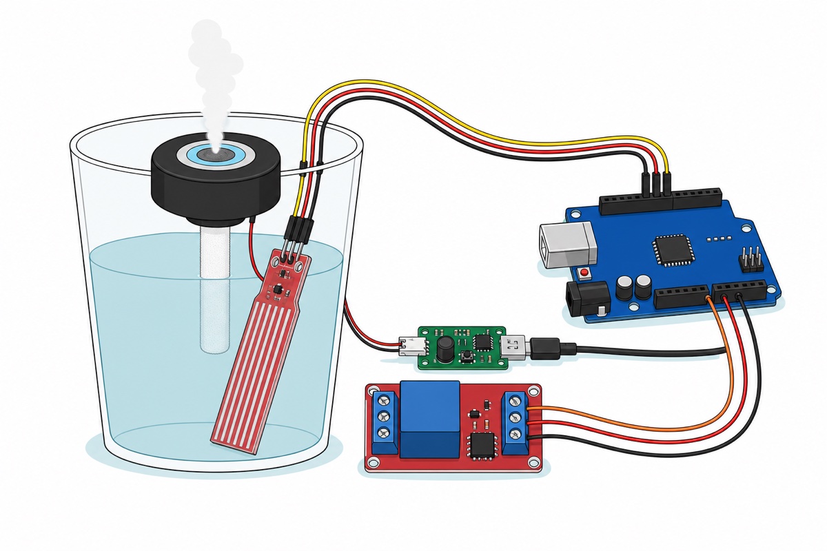
| Uno A0 | HW-038 S pin | M-F jumper |
| Uno D7 | HW-038 + pin | M-F jumper |
| Uno GND | HW-038 – pin | M-F jumper |
| Transducer JST plug | Driver board CN1 socket | Supplied lead, one orientation only |
Two supplies run this build and they never meet: the mist module drinks from its own charger through the cut cable, while the Uno keeps its own USB lead to a computer or a second charger port. No row above joins charger negative to Uno GND, and that gap is deliberate — it is the isolation you bought when you chose an opto-coupled relay.
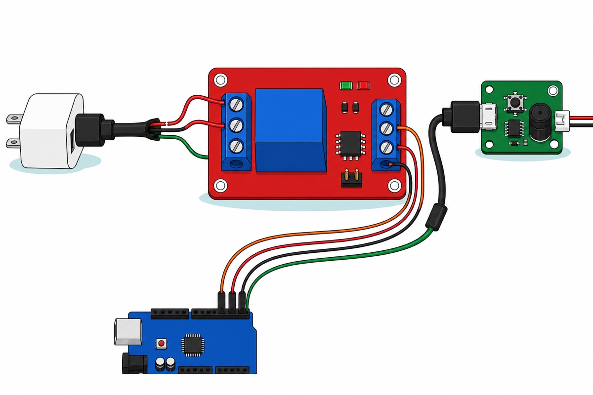
A MOSFET works here too, but it switches the negative conductor instead — see the FAQ and our IRF520 module guide.
How do you stop the mist maker from ever running dry?
The HW-038 water level sensor is not a float switch. Its ten exposed silver fingers are two interleaved combs, and water bridging them is simply a resistor: the deeper the paddle sits, the more parallel conducting paths there are and the lower that resistance falls. A transistor turns the change into a voltage, so A0 reads a number that climbs with depth across the paddle’s 40 mm sensing zone — a relative reading, not millimetres, so it needs calibrating in your own tank.
Because it senses by pushing current through water, leaving it permanently powered electrolyses its own electrodes and the exposed traces corrode within days. Power it from a digital pin instead: under 20 mA sits right at the Uno’s recommended per-pin figure — no margin, but nothing exceeded — and the sketch holds that pin high for only ten milliseconds per reading.
Where the paddle sits decides whether any of this works. Its lowest finger must be above the depth at which the wick stops reaching water, so the cut happens while the plate is still wet. A threshold set for an empty glass is the same as no sensor at all.
Calibrate first: print the value with the paddle in air, then at the lowest level you will run, and set TOO_DRY just under that with WET_ENOUGH comfortably above. The gap is deliberate — without it the mist chatters around one boundary value. Our water level sensor guide and plant watering build use the same pattern.
One more thing the sketch does, and it is what separates a cut-off that usually works from one you can rely on: it checks the sensor before trusting it. A signal wire working loose would quietly defeat the whole design, because a disconnected A0 is not a low reading — it is a floating input holding charge from the previous conversion, so it can sit above the wet threshold and keep the mist running over an empty tank. Powering the sensor from a pin buys a free test for that: read A0 once before energising D7. A connected sensor can only pull that line down, so anything more than a small residue means it is not there, and the sketch refuses to mist.
/*
  Mist maker with dry-run shutoff - Arduino Uno
  The Uno never powers the mist module. It only closes a relay contact
  that sits in the +5V conductor of the module's own charger cable.

  D8  -> relay IN   (H/L jumper on H, so HIGH = contacts closed = mist on)
  D7  -> HW-038 "+" (sensor is only powered for the instant of a reading)
  A0  <- HW-038 "S"
  GND -> HW-038 "-" and relay DC-, 5V -> relay DC+
*/

const uint8_t RELAY_PIN  = 8;
const uint8_t SENSOR_PWR = 7;
const uint8_t SENSOR_SIG = A0;

// Calibrate these on YOUR tank: print the raw value with the fingers dry,
// then with the water at the lowest level the disc may still run at.
const int TOO_DRY     = 260;  // below this, cut the mist immediately
const int WET_ENOUGH  = 320;  // above this, it is safe to start again

// With SENSOR_PWR low, a connected sensor can only pull A0 down. A reading
// above this with the sensor unpowered means the S wire is off and the input
// is floating - never mist on a value we cannot trust.
const int UNPOWERED_MAX = 100;

const unsigned long MIN_OFF_MS  = 60000UL;  // settle time after a dry cut
const unsigned long READ_EVERY  = 1000UL;

bool misting = false;
unsigned long lastOff = 0;
unsigned long lastRead = 0;

int readLevel() {
  analogRead(SENSOR_SIG);           // flush the stale sample first
  if (analogRead(SENSOR_SIG) > UNPOWERED_MAX) {
    return -1;                      // sensor missing or miswired
  }
  digitalWrite(SENSOR_PWR, HIGH);   // energise the electrodes
  delay(10);                        // let the divider settle
  analogRead(SENSOR_SIG);           // throw the first conversion away
  int value = analogRead(SENSOR_SIG);
  digitalWrite(SENSOR_PWR, LOW);    // and de-energise them again
  return value;
}

void setup() {
  pinMode(RELAY_PIN, OUTPUT);
  digitalWrite(RELAY_PIN, LOW);     // mist off before anything else happens
  pinMode(SENSOR_PWR, OUTPUT);
  digitalWrite(SENSOR_PWR, LOW);
  Serial.begin(9600);
  Serial.println(F("mist guard ready"));
  lastOff = millis();
}

void loop() {
  if (millis() - lastRead < READ_EVERY) {
    return;
  }
  lastRead = millis();

  int level = readLevel();
  if (level < 0) {
    Serial.println(F("sensor not answering - mist stays OFF"));
  } else {
    Serial.print(F("level = "));
    Serial.println(level);
  }

  if (misting && level < TOO_DRY) {
    digitalWrite(RELAY_PIN, LOW);
    misting = false;
    lastOff = millis();
    Serial.println(F("water low - mist OFF"));
  } else if (!misting && level > WET_ENOUGH &&
             millis() - lastOff > MIN_OFF_MS) {
    digitalWrite(RELAY_PIN, HIGH);
    misting = true;
    Serial.println(F("water back - mist ON"));
  }
}
That compiles to 2,694 bytes, eight percent of the Uno’s flash. Note what setup() does first: it drives the relay pin low, so the mist cannot start before the sensor has been read once. MIN_OFF_MS then holds it off for a minute after any dry cut, so a ripple or a splash cannot restart a hot plate the instant the water brushes the threshold — and because setup() starts that timer as well, the first minute after power-up is quiet too. That opening pause is deliberate, not a fault.
Common mistakes we see
Connecting the disc’s red and black leads straight to 5 V DC. The transducer is not a DC load — it needs 108 kHz alternating drive, which is the driver board’s entire job. On DC it does nothing, which gets read as a dead disc.
Running it dry for a few seconds “just to check it works”. There is no safe short version of that check. Wet the wick, or float the disc in a saucer, first.
Letting the wick sit above the water line. A wick lifts water only while its lower end is submerged, so it goes dry long before the tank looks empty.
Submerging the disc to “make sure it stays wet”. This type mists from a wetted face into open air — water underneath, mist off the top. Sink it and you get bubbles and a muffled buzz instead of a plume; the wick exists precisely so the disc can stay above the waterline while the water comes up to it.
Standing the electronics beside an open plume. Fog that does not drift away condenses on whatever is nearest, and a film of water across the relay board or the sensor’s own header pins is how a build that worked on day one starts reading strangely in week two.
FAQ
Can I control an ultrasonic mist maker module directly from an Arduino pin?
No. The module is rated 5 V, 300 mA and 2 W, and the figure to design with is the larger one those ratings imply: 2 W ÷ 5 V = 0.4 A, about twenty times the 20 mA an Uno pin is specified for. Switch its supply instead: relay contacts or a MOSFET in the 5 V line from its own charger, with the pin driving only the relay’s opto-isolator input.
Why did my mist maker stop making mist after a few minutes?
Most likely the plate ran dry. The water is the working fluid, the mechanical load and the ceramic’s only cooling, so once it goes the drive energy becomes heat, and piezoelectric material depolarises when it gets hot enough without recovering on cooling. Usually the wick lost contact with a falling level rather than the tank being empty.
Do I need a water level sensor, or will the module shut itself off?
Fit the sensor. A teardown of this class of driver shows an open-loop oscillator with no feedback from the plate, so the board cannot tell wet from dry; the only measure its documentation describes is a timed auto-shutdown after four or eight hours, which is a clock, not a water sensor. The dangerous case is a partly wet plate: the mist thins but never stops, and the dry area overheats. A resistive sensor such as the HW-038 answers unambiguously.
How much mist does one module make, and can it humidify a room?
One plate of this class is quoted at around 50 ml of water an hour — about 1.2 litres a day flat out. That is desk, terrarium, display-piece and cabinet territory, not bedroom territory; a room humidifier moves several times as much. For a custom humidifier with real output you gang plates, and each plate needs its own driver board — the board’s oscillator and output stage carry a 2 W, 300 mA budget sized for exactly one transducer, so hanging a second disc on the same output splits the drive between them and neither one mists properly.
Can I use tap water in a DIY ultrasonic humidifier?
It works, but it costs plate life and puts dust on your furniture. Everything dissolved in the water stays behind as each droplet evaporates: inside holes a few microns wide that becomes scale, and in the room it becomes fine white dust. Distilled water avoids both, and keep essential oils out — oil does not evaporate off the plate, so it clogs the holes.
Can I use a MOSFET instead of a relay to switch the mist module?
Yes, and it is quieter with no contacts to wear, but two things change. A low-side MOSFET module interrupts the negative conductor rather than the positive, so you cut the black wire of the sacrificial cable instead of the red. And the IRF520 is not logic-level: a 5 V gate turns it on only partially and a 3.3 V gate barely at all, showing up as heat rather than a clean switch.
Last updated August 2026. Stuck? Chat with us on WhatsApp.
