

Tutorials
Blynk + ESP32: Control a Relay From Your Phone
Aug
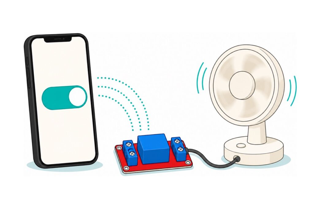
Yes — your phone can switch a relay through the free Blynk IoT cloud: create a template at console.blynk.cloud, copy its three #define lines to the very top of the sketch below, and wire a 5 V relay module to an ESP32 with three jumper wires. It also builds the part most tutorials skip: a switch that still works when the internet dies.
What do you need to control a relay from your phone?
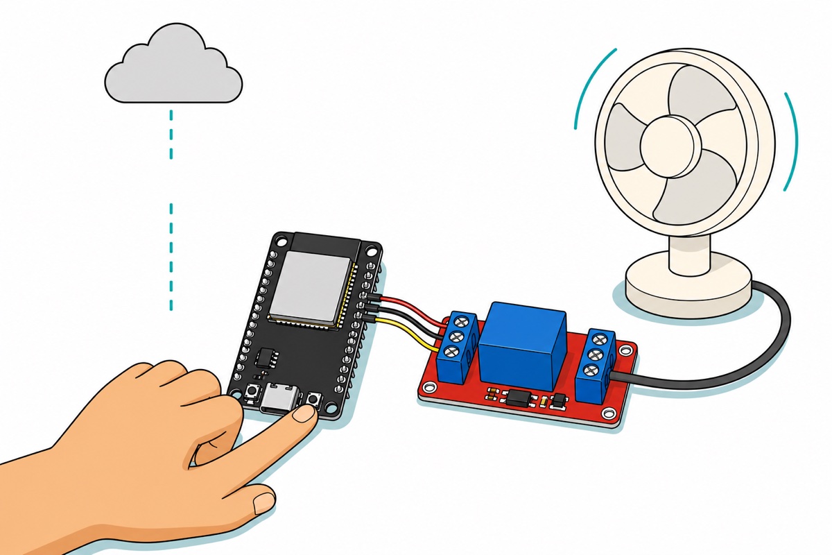
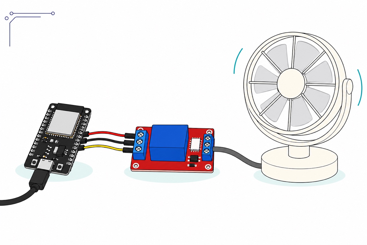
A Blynk relay build is a four-link chain: the Blynk app on your phone talks to Blynk’s cloud, the cloud pushes each toggle to your ESP32 over home Wi-Fi, and one ESP32 pin drives a relay module whose contacts switch the real load — a 12 V fan, LED strip or pump.
Parts list — phone-controlled relay, fully solder-free
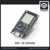 NodeMCU ESP32 Wi-Fi + Bluetooth Development Board CH340/CP2012 - For IOT Project - ESP-32 (CH340)
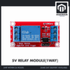 Relay Module 3.3V 5V 12V 1/2/4/8 Ways Optocoupler Trigger Relay Module 1 2 4 8 Channel Relay Module - 5V RELAY MODULE(1WAY)
 40pcs Dupont Wire 10cm 20cm 30cm for Breadboard DIY Experiment Jumper Wire Breadboard wire - DUPONT WIRE M-F 20CM
 Data Cable Type-A Type-C MicroUSB Type-B 0.5m 1m 30cm 0.3m 100cm Data Transfer Upload Code - TYPE-A TO TYPE-C CABLE (1.0M)
Parts list
| Item | Price | Qty | |
|---|---|---|---|
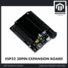 NodeMCU ESP32 Wi-Fi + Bluetooth Development Board CH340/CP2012 - For IOT Project - ESP32 30PIN EXPANSION BOARD32DEVBD-X32ECH34 NodeMCU ESP32 Wi-Fi + Bluetooth Development Board CH340/CP2012 - For IOT Project - ESP32 30PIN EXPANSION BOARD32DEVBD-X32ECH34 | RM8.90 |
Optional 30-pin expansion board that seats this exact DevKit — every pin broken out beside 5 V and GND rails, plus a DC barrel jack. The tidy base once you start adding more relays and sensors.
The purple ESP32-C2 board is this DevKit’s compact single-core RISC-V sibling for ESP-IDF work — the standard Arduino board manager does not support the C2, so it cannot follow this Arduino-IDE tutorial; every Blynk example is written for the classic 30-pin CH340 DevKit. The same relay family also comes with a 12 V coil — pick the coil that matches a supply you already have; the 5 V version runs straight off USB power.
What are a Blynk Template, Datastream and Auth Token?
Blynk IoT organises everything around three ideas. A Template is the blueprint of a product: which data channels exist and what the dashboard looks like. A Device is one real board created from that blueprint, and the Auth Token is that device’s login key — a long random string telling the cloud who is connecting and what it may control. A Datastream is one named channel between app and board; ours is Virtual Pin V0, carrying 0 or 1.
The setup takes five minutes at console.blynk.cloud — Blynk’s own quick-setup guide mirrors these clicks: Developer Zone → My Templates → New Template (hardware ESP32, connection WiFi). Inside it, add a Datastream on Virtual Pin V0, type Integer, range 0–1, and, on the web dashboard, a Switch widget bound to V0. Then create a New Device from the template — its Device Info tab shows the three #define lines ready to copy. The phone dashboard is separate: in the Blynk IoT app, open the device, tap the wrench icon and add a Button widget bound to V0, mode Switch — until then the app shows an empty screen.
Those three lines must sit above every #include: an #include is a textual paste, and the Blynk library reads the defines at the moment it is pasted in. Put them lower and the library sees nothing there — the build stops with the library’s own error, “Please specify your BLYNK_TEMPLATE_ID and BLYNK_TEMPLATE_NAME”.
Treat the token like a password — anyone holding it can operate your relay from anywhere, so keep it out of chats, screenshots and public repos. If yours has leaked, delete the device in the console and create a new one from the same template — the replacement carries a fresh token, and the leaked one no longer matches anything.
Prefer to see the console setup clicked through on screen first?
How do you wire the relay module to the ESP32?
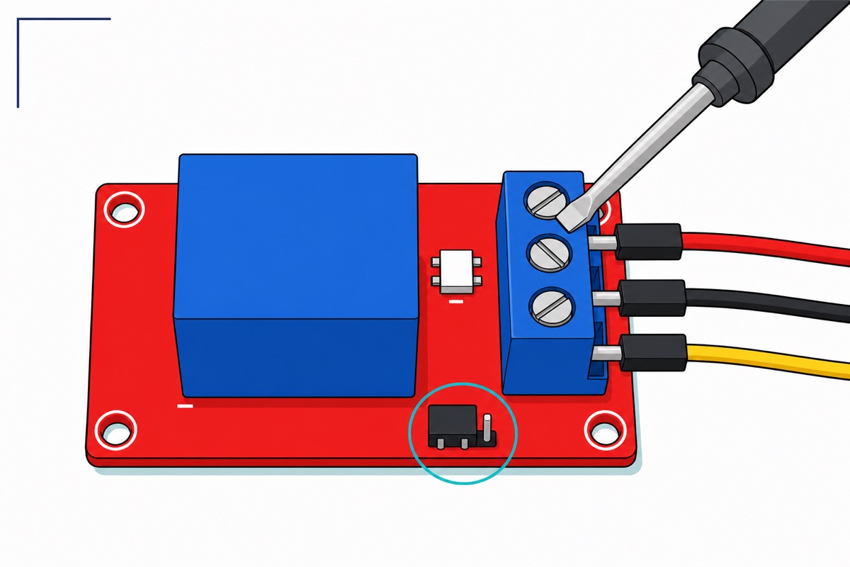
The 1-way relay module’s control side is a 3-way screw terminal marked IN, DC− and DC+ — not header pins — so the parts list uses male-to-female jumpers: female ends onto the DevKit’s pre-soldered pins, bare male tips clamped under the screws.
| Relay terminal | DevKit pin | Why |
|---|---|---|
| DC+ | VIN | The coil is a 5 V electromagnet — VIN carries the USB port’s 5 V straight through |
| DC− | GND | Common return for coil current and the control signal |
| IN | D26 | GPIO26 — an ordinary full output pin that stays quiet from power-up |
Your load connects to the output terminal on the other edge: COM in the middle, NO (normally open) beside it, so the circuit is dead until the relay pulls in. The relay is just a switch spliced into the load’s own supply line: positive from that supply into COM, out from NO to the load, negative straight through. Power the coil from VIN, not the 3V3 pin: the SRD-05VDC coil measures about 70 Ω, so at 5 V it draws roughly 70 mA — trivial for USB power (more in our ESP32 power guide). The 3V3 pin also cannot close it: Songle rates pull-in at 75% of the rated coil voltage — about 3.75 V — so 3.3 V may never pull the armature in at all.
At reset the ESP32 samples its strapping pins — GPIO0, 2, 5, 12 and 15 — to decide how to boot, and wobbles them while it does, which clicks a relay at every restart. GPIO34, 35, VP and VN fail differently: input-only, no output driver at all. D26 has neither problem.
The black trigger-select jumper ships on L (low-level trigger) — leave it there. Low-trigger is what lets a 5 V module obey a 3.3 V board: the ESP32 pin never has to supply 5 V, only to sink a few milliamps from the optocoupler’s input LED, fed from the module’s own DC+ rail. Pull IN low and that current flows — relay on. Drive IN high at 3.3 V and only 5 − 3.3 = 1.7 V remains across the input chain, well below the ~3 V the indicator LED and opto LED in series need to conduct — so it stays off cleanly in both states.
Safety first: the blue relay cube is printed with mains-sized contact ratings, but this build stays strictly on low-voltage DC loads. Switching mains needs enclosures, creepage clearance and strain relief a bare module on a desk does not have — our relay safety guide explains the contact side properly.
What does the Blynk ESP32 code look like?
The sketch is built around Blynk.config() instead of the Blynk.begin() every copy-paste example uses — that choice is the whole offline story, explained next. Install the Blynk library by Volodymyr Shymanskyy from Library Manager, select ESP32 Dev Module as the board, swap in your own three #define lines and Wi-Fi details — a 2.4 GHz network name, since the ESP32’s radio cannot see 5 GHz-only SSIDs — and upload.
// Blynk + ESP32 phone-controlled relay, with an offline manual override.
// These three defines MUST stay ABOVE every #include - the Blynk library
// reads them while it is being included. Copy the real values from YOUR
// device page at console.blynk.cloud; these are placeholders.
#define BLYNK_TEMPLATE_ID   "TMPL_PASTE_YOURS"
#define BLYNK_TEMPLATE_NAME "Phone Relay"
#define BLYNK_AUTH_TOKEN    "PASTE-YOUR-OWN-TOKEN-HERE"  // SECRET - never share it

#define BLYNK_PRINT Serial            // connection log in Serial Monitor

#include <WiFi.h>
#include <BlynkSimpleEsp32.h>

const char WIFI_SSID[] = "YourWiFiName";
const char WIFI_PASS[] = "YourWiFiPassword";

const int  RELAY_PIN = 26;            // silkscreen D26 - quiet at boot
const int  BOOT_BTN  = 0;             // the DevKit's own BOOT button
const int  RELAY_ON  = LOW;           // trigger jumper ships on L (low = on)
const int  RELAY_OFF = HIGH;

bool relayState = false;              // what the relay should be doing
unsigned long lastRetry = 0;
const unsigned long RETRY_EVERY = 30000UL;   // ms between cloud retries

void applyRelay() {
  digitalWrite(RELAY_PIN, relayState ? RELAY_ON : RELAY_OFF);
}

// Runs every time the app's V0 switch changes
BLYNK_WRITE(V0) {
  relayState = param.asInt();         // 1 = on, 0 = off
  applyRelay();
}

// Runs each time the cloud link comes (back) up
BLYNK_CONNECTED() {
  Blynk.syncVirtual(V0);              // ask the server for V0's last value
}

void setup() {
  pinMode(RELAY_PIN, OUTPUT);
  applyRelay();                       // relay OFF before anything else
  pinMode(BOOT_BTN, INPUT_PULLUP);    // pressed = LOW
  Serial.begin(115200);

  WiFi.begin(WIFI_SSID, WIFI_PASS);   // starts connecting in the background
  Blynk.config(BLYNK_AUTH_TOKEN);     // configure only - never blocks
  Blynk.connect(5000);                // try for 5 s, then move on regardless
}

void loop() {
  if (Blynk.connected()) {
    Blynk.run();                      // service the cloud link
  } else if (millis() - lastRetry > RETRY_EVERY) {
    lastRetry = millis();             // one bounded retry every 30 s
    if (WiFi.status() == WL_CONNECTED) Blynk.connect(5000);
  }

  // Manual override: BOOT button toggles the relay, internet or not
  static bool lastBtn = HIGH;
  bool btn = digitalRead(BOOT_BTN);
  if (lastBtn == HIGH && btn == LOW) {          // a new press
    delay(30);                                  // debounce
    if (digitalRead(BOOT_BTN) == LOW) {
      relayState = !relayState;
      applyRelay();
      if (Blynk.connected()) Blynk.virtualWrite(V0, relayState);
    }
  }
  lastBtn = btn;
}
It compiles to 913,759 bytes — about 69% of the DevKit’s app space. Flip the app’s switch and the relay answers within a fraction of a second. No relay on the desk yet? Change RELAY_PIN to 2 and swap the RELAY_ON and RELAY_OFF values, and the same template runs the classic Blynk LED on-off demo on the DevKit’s blue onboard LED — a strapping pin, fine for a blink, never for the relay.
How does the switch keep working when the internet is down?
Blynk.begin() is why most Blynk switches are dumber than a wall switch. Inside the library it is two unbounded waits: a loop spinning until Wi-Fi connects, then while(connect() != true) {} until the cloud answers. If the router is off, the sketch never leaves setup(): no loop, no button, a relay frozen in its last state.
The replacement splits the job: Blynk.config() only stores the token and server name, so it cannot block; Blynk.connect(5000) tries for five seconds, then returns and lets the sketch run either way; and the loop retries once every 30 seconds while Wi-Fi is up. The trade: during a retry the button can wait up to five seconds, once per half-minute — both numbers are tunable.
The manual override uses the DevKit’s own BOOT button (GPIO0) — only special at reset, when the chip samples it to decide whether to enter the bootloader; afterwards it is an ordinary input with a pull-up, reading LOW while pressed. The sketch watches for that edge and toggles the relay.
When the link returns after an outage, BLYNK_CONNECTED() fires and syncVirtual(V0) replays the switch’s last server value — the app’s setting wins, so the phone display never lies. Prefer the wall-button state to win? Replace that line with Blynk.virtualWrite(V0, relayState), which pushes the board’s state up instead.
Common mistakes we see from real customers
“so can include with the blynk?” — Asked about everything from medical-robot FYPs to ESP32-CAM streams — almost always yes: Blynk bolts onto whatever the sketch already does, on two conditions. The three defines go at the very top, and nothing in loop() may block — a long delay() starves Blynk.run(), the cloud misses its heartbeat, and the app shows the device offline. Time slow work with millis(), like the retry timer above.
“what you gonna monitor in the blynk?” — the answer is whatever you give a datastream. V0 here carries a command down to the relay; monitoring is the same machinery pointed up — one datastream per reading, written with Blynk.virtualWrite() from your sensor code, in the same template.
Pasting a live auth token into a group chat. Whole sketches get shared for help with the token still inside — whoever scrolls past can now flip your relay. Blank it before sharing code; replace a leaked one as described above.
Uploading through a charge-only USB cable. The board powers up and looks alive, but no serial port ever appears — two of the cable’s four wires are missing. That is what the parts list’s USB-C data cable is for; if the port still hides, our ESP32 upload-fix guide walks the chain.
FAQ
Why does Blynk say “Invalid auth token”?
The token in the sketch no longer matches any device — a copy-paste that lost a character, a device deleted and re-created after a leak, or a template from another account. Copy the three lines fresh from Device Info and re-upload.
Is the free Blynk plan enough for this build?
Yes — one template, one device and a switch widget sit comfortably inside the free tier. Blynk adjusts limits from time to time, so check the console’s plan page rather than numbers printed in tutorials.
Can I use the 12 V relay module instead?
Yes, if your system already has a 12 V supply: DC+ to that supply, DC− to a ground shared with the ESP32, and IN still to D26 — the optocoupler works the same way. A 12 V coil fed from the DevKit’s 5 V VIN simply will not pull in.
Why does my relay click on its own when the ESP32 restarts?
The IN wire is on a strapping pin — GPIO0, 2, 5, 12 or 15 — which the chip wiggles at every reset while deciding how to boot. Move it to a quiet full-output pin such as D26, D27, D25 or D33.
Once the phone controls the relay, the same wiring carries into our other builds: the offline voice-control relay drives this exact module with spoken commands instead of an app, and our ESP32-CAM stream guide adds the camera half of many FYP briefs. Template, token, three wires — and the relay answers to your pocket.
Last updated August 2026. Stuck? Chat with us on WhatsApp.

Pingback: ESP-01S Wi-Fi Relay Module: How to Flash It and Wire a Load