

Tutorials
12V Timer Relay Module: Wiring, Modes and Setting the Time
Aug
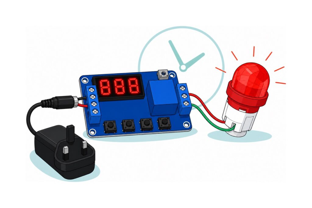
A 12 V delay timer relay module is wired in two halves and programmed with two decisions. One screw terminal takes 6–30 V and a trigger; the other is a bare switch — NO, COM, NC — carrying the load’s own circuit. Then pick the P mode, which sets the behaviour, and place the decimal point, which decides whether the digits mean tenths of a second, seconds or minutes.
What goes into a 12V delay timer relay build?
The multi-function relay module is a royal-blue board roughly 62 × 38 mm carrying a red three-digit display, four buttons silkscreened STOP, SET, UP and DOWN, and one blue screw terminal at each end. Everything else here gives it a supply, a trigger and something visible to switch — no soldering, no code.
Parts list — 12V delay timer relay auto-off light, no soldering and no code
 Multi Function Relay Module Time Delay Timer Switch Control Board DC 12V 24V AC 110V 220V Programmable Automation
 Power Supply Adapter DC Universal AC to DC Converter PSU 5V2A 5V3A 9V2A 12V2A - P.S. ADAPTOR (12V2A)
 5.5x2.1mm DC Power Male Connector Plug Jack Adapter for Arduino DIY Electronics Projects - 5.5x2.1 DC CONNECTOR (F)
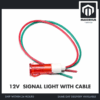 Signal Light 12V 24V Red Yellow Green Indicator Warning Light with Optional Cable Industrial Safety Light - 12V SIGNAL LIGHT WITH CABLE (RED)
 40pcs Dupont Wire 10cm 20cm 30cm for Breadboard DIY Experiment Jumper Wire Breadboard wire - DUPONT WIRE M-M 20CM
Optional — a cheaper single-mode board, and a fan for the off-delay demo
 Delay Trigger Relay Module DC 12V Time Delay Switch Circuit Timer Control Board Adjustable Timing
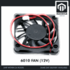 DC Cooling Fan 5V/12V Brushless Small Fan for 3D Printer DIY Projects Electronics Cooling - 6010 FAN (12V)
The NE555 delay board is the fixed-and-forget alternative: one trimmer, one behaviour, no display. The 60 mm 12 V fan is the second worked load, used to demonstrate the run-on (off-delay) setting.
Connector shape decides whether the parts fit at all. The 12 V 2 A adapter ends in a 5.5 × 2.1 mm male barrel plug, which is what the female barrel pigtail receives, and the pigtail’s other end is bare red and black wire — what a screw terminal wants. The 12 V signal light also ends bare, but in red and green rather than the red and black most people expect, so read green as return. The male-to-male dupont pack supplies the short links, since a square male pin clamps under a screw as well as stripped wire does. The rows above render live stock; if one reads zero, message us.
The NE555 delay board is the fixed-and-forget lane: a trimmer instead of a display. Its contacts read CK / COM / CB, the pinyin initials of 常开 (normally open) and 常闭 (normally closed), so CK is NO and CB is NC; its silkscreen name 延时导通 means the delay runs from power-up, not from a trigger. Its trimmer spans roughly 0–10 seconds, not minutes, and with no display you set it against a stopwatch.
Which timer relay mode do you need — on-delay, off-delay or cycle?
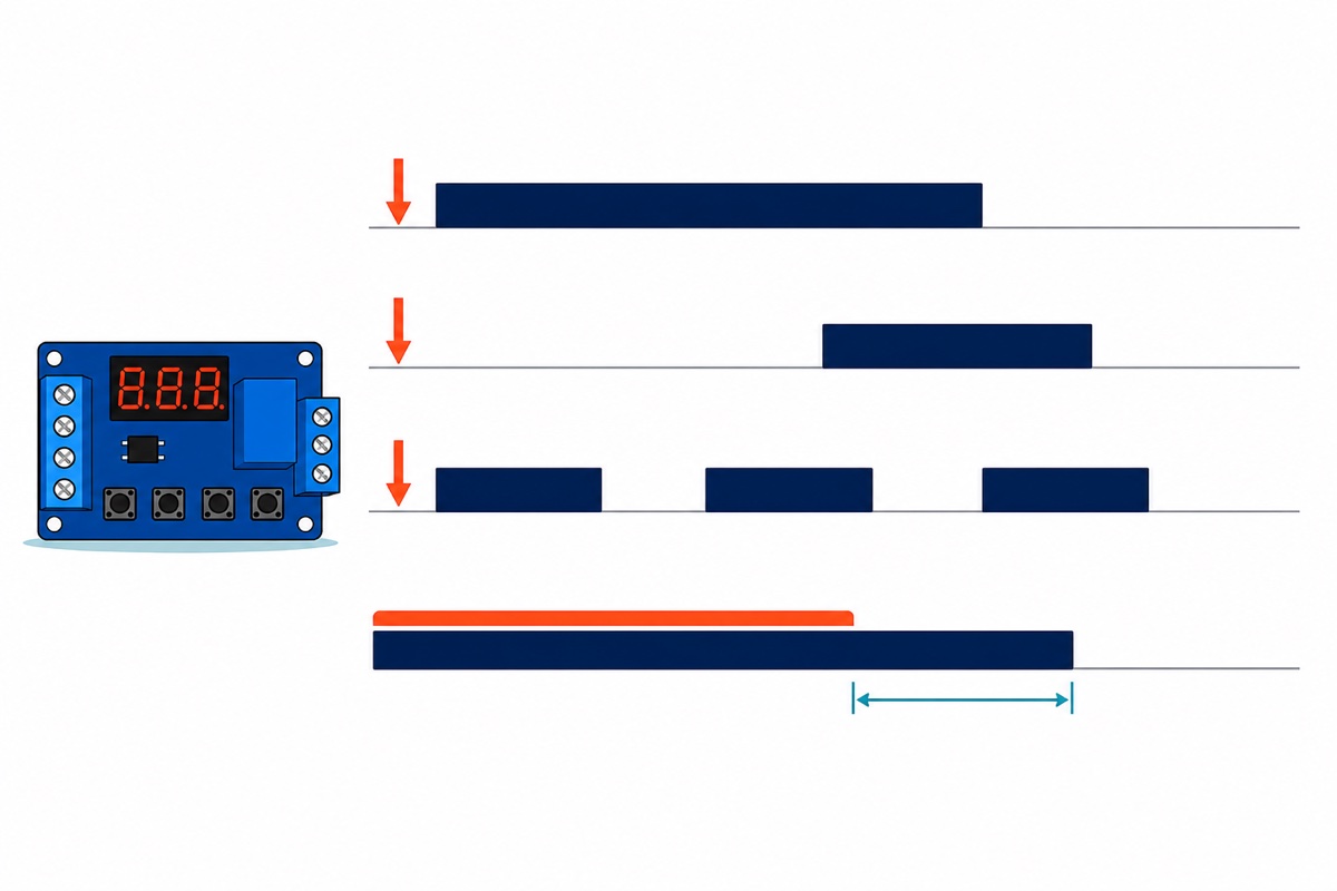
The multi-function relay module is an XY-J02-family board, and its seven modes are why one part does the work of several fixed-function time delay switches. OP is the on time, CL the off time, LOP a cycle count.
| Mode | What the relay does | Parameters |
|---|---|---|
| P1.1 | Trigger → on for OP, then off. A second trigger during OP is ignored | OP |
| P1.2 | Same, but a second trigger during OP restarts the clock from zero | OP |
| P1.3 | Same, but a second trigger during OP cancels it: relay off, timing stopped | OP |
| P2 | Trigger → stays off for CL, then on for OP, then off. This is on-delay | CL, OP |
| P3.1 | Trigger → on OP, off CL, repeating LOP times; a trigger mid-cycle stops it | OP, CL, LOP |
| P3.2 | The same cycle, but free-running from power-on with no trigger at all | OP, CL, LOP |
| P4 | On while the trigger is present; once it disappears, off after OP. This is off-delay | OP |
A push-button that switches something on and lets it turn itself off is P1.1. A pump that must not start the instant a float switch closes is P2. Anything repeating unattended is P3.2, with LOP set to --- for an endless loop — the job our plant watering guide hands to a microcontroller. No mode latches: every one ends with the relay released. A delay that switches something on and leaves it on until you pull the plug is not a setting here — it is P2 with OP wound out to its 999-minute maximum, about sixteen and a half hours. Elapsed time is all this board reasons about, so once the decision depends on a threshold or a phone you want something that runs code, like the ESP32 in our Blynk relay guide.
This walkthrough steps through P1 to P4 on the same board:
How do you set the time on a three-digit display?
The multi-function relay module spans 0.1 seconds to 999 minutes, and three digits cannot express both ends at once. So the decimal point is not decoration: its position is the unit band, and a short press of STOP walks it along while a parameter is being set.
| Decimal point | Display looks like | Range it selects |
|---|---|---|
| After the tens digit | XX.X | 0.1 – 99.9 seconds |
| After the ones digit | XXX. | 1 – 999 seconds |
| All three lit | X.X.X. | 1 – 999 minutes |
So 03.2 is 3.2 seconds, 030. is 30 seconds, and 030 with all three points lit is 30 minutes. The order is fixed: hold SET two seconds to enter mode selection, short-press UP or DOWN to your mode, short-press SET to reach the first parameter, which flashes. Adjust with UP and DOWN — short press moves one unit, long press runs fast — short-press STOP to place the decimal point, short-press SET for the next parameter, then hold SET again to save and leave.
Parameters are shared across modes rather than stored per mode: set OP to 5 seconds in P1.1, switch to P1.2, and OP is still 5 seconds. The main screen reads 000 with no decimal point while the relay is idle, with a point lit while timing runs, so the display doubles as a state indicator. A short press of SET there replays the mode’s parameters, and a press of STOP aborts a run already under way — timing stops, the relay releases, the display returns to 000.
How do you wire the 12V auto-off light?
The multi-function relay module prints its four-way terminal labels on the rear silkscreen only, so turn it over once and then work from the front: display up and buttons along the bottom edge, the left block reads ~30V, GND, Trigger, GND_T from top down and the right block NO, COM, NC. Only the power side needs that flip — the contact labels are printed on the front. Trigger and GND_T are not connected to the board’s ground at all: they are the two legs of the LED inside the PC817 optocoupler sitting mid-board, with a series resistor ahead of it. That is why the trigger accepts anything from 3.0 V to 24 V — the LED itself drops only about 1.2 V and wants a few milliamps; the resistor swallows the rest. It is also why GND_T is its own terminal: that LED needs a return path, and on a single supply that path does not exist until you make it.
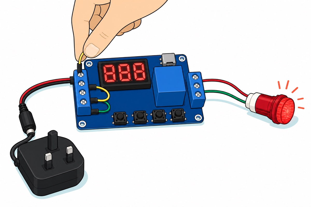
So the first jumper links GND_T to GND — leave it out and the trigger wire can sit at 12 V all day with nothing happening.
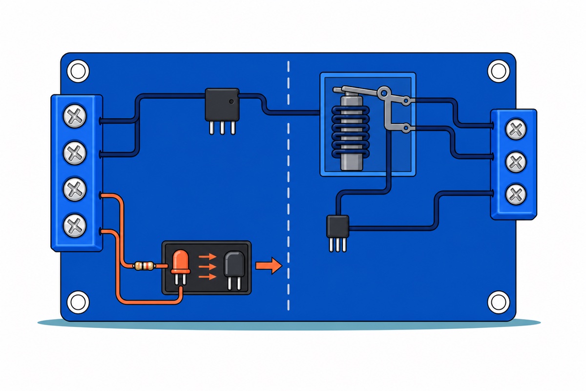
The contact side is a bare mechanical switch. The coil drags an armature across, and that armature carries no power of its own — NO and COM cannot supply the lamp, only join it to something else. The lamp’s current comes from the adapter instead: a second dupont link from ~30V to COM brings 12 V to the switch, NO carries it out when the relay pulls in, and the lamp returns to GND. That jumper is the load’s supply, so the load has to suit whatever the board runs on — the same link on a 24 V adapter puts 24 V across a 12 V lamp. It need not be the same rail either: dry contacts will carry a separate circuit with its own battery. NC is the same switch inverted, closed until the relay operates — our relay module guide takes all three apart.
| From | To | Why |
|---|---|---|
| Adapter barrel plug | Pigtail barrel socket | The only tool-free joint in the build |
| Pigtail RED | ~30V |
Board supply, anywhere in 6–30 V — this screw takes two wires |
| Pigtail BLACK | GND |
Board ground — this screw takes two wires |
GND_T |
GND (dupont link) |
Return path for the optocoupler LED; without it nothing triggers |
~30V |
COM (dupont link) |
The contacts carry no power of their own — this is the lamp’s supply |
NO |
Lamp RED lead | Open until the relay pulls in |
| Lamp GREEN lead | GND_T |
Same node as GND once the jumper is in, so GND_T doubles as a second ground post |
COM |
Trigger (momentary touch) |
Same node as ~30V once the jumper is in; 12 V sits inside the 3.0–24 V trigger window |
Count the wire ends first: nine of them land in five screws, so four screws hold two each — ~30V takes the pigtail’s red and the jumper to COM, GND takes the pigtail’s black and the jumper to GND_T, which leaves those jumped terminals as spare posts for the trigger lead and the lamp’s green. Nothing holds three. Strip each pair the same short length, twist the strands tight, then lay them side by side in the jaw rather than stacked, because a stacked pair looks clamped and works loose. Power the board with nothing on the contact side first, set P1.1 with an OP of 030., brush the free end of the trigger lead against the Trigger screw and listen for the click, and only then wire the lamp.
The relay cube is a Songle SRD-05VDC-SL-C, a 5 V coil on a module sold for 12 V and 24 V. The black three-pin 78M05 regulator beside it turns whatever arrives at ~30V into a fixed 5 V for the microcontroller, the display and the coil, which is why the input range can be so wide — the coil only ever sees 5 V. The micro-USB socket feeds that same rail, so a power bank will run the buttons before any 12 V is connected.
Swapping the lamp for the 60 mm 12 V fan demonstrates off-delay properly: set P4 with an OP of two minutes, hold the trigger lead against the Trigger screw and the fan runs; lift it away and the fan keeps going two minutes more. The fan ends in a small white JST plug, so push a male dupont pin into each socket or snip the plug off. A brushless fan commutates its own windings behind a driver chip in the hub and draws a fraction of an amp at 12 V, so contacts rated in amps barely notice it. Heavier DC inductive loads — a brushed motor, a solenoid, a pump — are the ones that wear contacts, because direct current has no zero current point at which an arc can quench itself. A diode across such a load’s own terminals, banded end to the positive side, gives that stored energy somewhere to circulate and spares the contact faces.
Can a 12V timer relay module switch 220V mains?
The Songle relay’s case is printed 10A 250VAC and 10A 30VDC, and those ratings are real — the contacts are metal, and metal does not care what is on the other side. The module around them is not built for mains: no enclosure, no earth, and nothing but bare board between the contact screws and the low-voltage terminals and buttons you handle while setting the time. Permanent mains work in Malaysia belongs to a contractor registered with the Energy Commission, and for an appliance on a timer the honest answer is a ready-made plug-in timer socket.
Common mistakes we see with timer relay modules
The trigger voltage is present and the board ignores it. GND_T has usually been left empty, so the optocoupler LED’s far leg is floating and voltage on the near one lights nothing. Link GND_T to GND on a single supply, or run the signal source’s ground there.
The delay is sixty times too long. That is the decimal point, not a fault: 030 with every point lit is thirty minutes, 030. is thirty seconds.
The relay clicks but the load stays dead. COM and NO are a switch, not an output. Nothing leaves through them unless a supply has been brought into COM — here, the dupont link from ~30V.
Changing mode quietly changed the time. It did not — OP, CL and LOP are shared, so re-check them after every mode change.
FAQ
What is the difference between an on-delay and an off-delay timer relay?
An on-delay waits before switching on: the signal arrives, nothing happens for the set time, then the relay operates — mode P2. An off-delay does the reverse, holding on while the signal is present and releasing only once it has been gone for the set time — mode P4, which is what a fan run-on needs.
Can I trigger the module from a sensor or a microcontroller?
Yes, if the source presents between 3.0 V and 24 V. An HC-SR501 outputs about 3.3 V on detection, clearing the 3.0 V threshold with little margin, so check on the bench that the relay actually fires before you rely on it — our PIR motion light guide covers it. A 3.3 V ESP32 pin is the same case; a 5 V Arduino pin has room to spare. Run the source’s ground to GND_T, not GND.
How do I set the timer to minutes instead of seconds?
While the parameter is flashing, short-press STOP until all three decimal points are lit. That selects the 1–999 minute band, so the value you dial is read as minutes.
Why does the display show 000 and nothing happens?
000 with no decimal point is the normal idle screen: powered, waiting, relay released. A decimal point appears while timing runs, so if none appears when you trigger, the fault is in the trigger loop — check GND_T first.
Does this timer relay need programming or an Arduino?
No. The board carries its own microcontroller and the four buttons are the whole interface, so this build has no code in it. A microcontroller earns its place only when the switching must depend on something other than elapsed time.
Last updated August 2026. Stuck? Chat with us on WhatsApp.

Pingback: Mini Aquaponics System for a School Project (RBT)