

Tutorials
ESP32 Web Server: Control a Relay From Any Browser
Aug
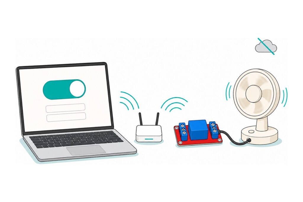
Yes — the ESP32 hosts the control page itself: flash the sketch below, open http://esp32.local/ or the board’s IP address in any browser on the same WiFi, and two buttons switch a 5 V relay module wired with three jumper wires. Nothing to install on the phone, no account, no internet — the request never leaves your router.
What do you need to control a relay from a browser?
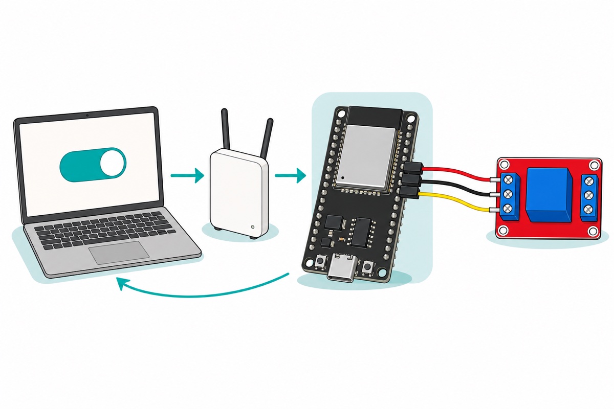
The ESP32 DevKit is the whole server here, and every link in this build sits inside your house: a browser asks it for a page, the board answers over your WiFi, and one of its pins drives a relay module whose contacts switch the real load — a 12 V fan, LED strip or pump.
Parts list — browser-controlled relay, no soldering and no breadboard
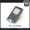 NodeMCU ESP32 Wi-Fi + Bluetooth Development Board CH340/CP2012 - For IOT Project - ESP-32 (CH340)
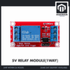 Relay Module 3.3V 5V 12V 1/2/4/8 Ways Optocoupler Trigger Relay Module 1 2 4 8 Channel Relay Module - 5V RELAY MODULE(1WAY)
 40pcs Dupont Wire 10cm 20cm 30cm for Breadboard DIY Experiment Jumper Wire Breadboard wire - DUPONT WIRE M-F 20CM
 Data Cable Type-A Type-C MicroUSB Type-B 0.5m 1m 30cm 0.3m 100cm Data Transfer Upload Code - TYPE-A TO TYPE-C CABLE (1.0M)
Optional — expansion base for when one relay becomes three
| Item | Price | Qty | |
|---|---|---|---|
 NodeMCU ESP32 Wi-Fi + Bluetooth Development Board CH340/CP2012 - For IOT Project - ESP32 30PIN EXPANSION BOARD32DEVBD-X32ECH34 NodeMCU ESP32 Wi-Fi + Bluetooth Development Board CH340/CP2012 - For IOT Project - ESP32 30PIN EXPANSION BOARD32DEVBD-X32ECH34 | RM8.90 |
Optional 30-pin expansion board that seats this exact DevKit: a DC barrel jack for 6.5–16 V input and every pin broken out beside its own 5 V and GND rails. The tidy base once one relay becomes three.
That expansion board’s breakouts are male pins, so pair it with female-to-female jumpers. Two nearby parts are deliberately absent: the purple ESP32-C2 is an ESP-IDF board the standard Arduino boards manager does not carry, and the same red relay board also comes with a 12 V coil — buy that one only if your system already runs a 12 V rail.
How does a web server fit inside an ESP32?
The ESP32 core’s WebServer library is a socket plus a lookup table. WebServer server(80) tells the chip to listen on TCP port 80, the port a browser uses for a plain http:// address. Open http://192.168.1.50/on and the browser sends one line of text: GET /on HTTP/1.1.
Each server.on("/on", handleOn) adds one row to that table — the path /on maps to the C function handleOn. That pairing is a route. server.handleClient(), called from loop(), checks whether a request is waiting, reads its path, finds the matching row and calls that function; the function writes text back down the same connection with server.send(), and the browser draws it.
Nothing else is involved, which is why there is no account to create. Packets go browser → router → ESP32 and back, so the switch keeps working when your internet line drops — only the WiFi has to be alive. The flip side: it works on your network only, which is what our Blynk phone-control guide trades away for a cloud hop that reaches you on mobile data. That also makes your WiFi password the only lock on the page: anyone already on the network can open it, so keep the board on the network you control rather than one you hand around.
Prefer to watch one serve its first page?
How do you wire the relay module to the ESP32?
The 1-way relay module’s control side is a 3-way screw terminal marked IN, DC− and DC+, not header pins — hence the male-to-female jumpers: female ends onto the DevKit’s pins, bare male tips clamped under the screws. Three wires, no breadboard, nothing to solder.
| Relay terminal | DevKit pin | Why |
|---|---|---|
| DC+ | VIN | The coil is a 5 V electromagnet; VIN carries the USB port’s 5 V straight through |
| DC− | GND | Common return for coil current and for the control signal |
| IN | D26 | GPIO26 — an ordinary full output pin that stays quiet through boot |
Feed the coil from VIN, not the 3V3 pin, and the numbers say why. The SRD-05VDC coil measures about 70 Ω, so 5 V pushes roughly 71 mA through it — nothing for USB power — but Songle specifies pull-in at 75% of rated coil voltage, about 3.75 V, so 3.3 V may never drag the armature across. Our ESP32 power guide covers the supply side.
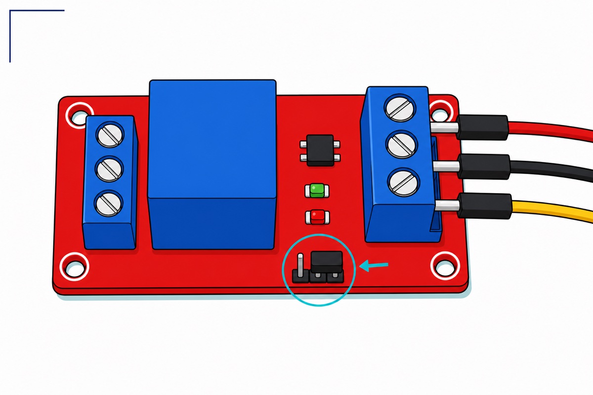
Set the module’s black trigger jumper to H, the high-level position, and RELAY_ON is HIGH. That jumper is the three-pin header along the board’s lower edge, beside the IN/DC−/DC+ terminal: the centre pin is the common one and the two outer pins are silkscreened L on the left and H on the right, so the black shunt bridges the centre pin to the right-hand pin. On H the optocoupler’s LED is driven from IN down to DC− through the module’s own 1 kΩ resistor, so a 3.3 V high pushes roughly 2 mA through it — a load an ESP32 pin sources comfortably — and 0 V stops it dead. L is the trap on a 3.3 V board: there the same LED hangs off the module’s DC+ rail instead and keeps conducting until IN climbs to within about 1.5 V of that rail, which is roughly 3.5 V on a 5 V module (traced schematic of this module). A 3.3 V high never reaches that line, so seated on L the relay pulls in the moment the module is powered and never releases.
GPIO26 is chosen for the same reason. At reset the ESP32 reads its strapping pins — GPIO0, 2, 5, 12 and 15 — to decide how to boot, wobbling them while it decides, which clicks a relay at every restart. GPIO34, 35, 36 and 39 fail the other way: input-only pads with no output driver, so they cannot switch anything. GPIO26 has neither problem, and while it is still an unconfigured input at power-up it sources nothing into the H-position chain, so the relay starts off.
The load goes on the opposite edge: positive from its own supply into COM, out from NO (normally open) to the load, and the load’s negative straight back to that same supply — dead until the relay pulls in. Wire it to NC instead and the load runs until the relay fires. Those three terminals are a mechanical switch sealed inside the blue cube, isolated from the coil and from the ESP32, so the load’s supply needs no ground in common with the board. Keep it low-voltage DC: the blue cube carries mains-sized contact ratings, but mains switching needs enclosure, creepage clearance and strain relief a bare desk board has not got. Our relay safety guide covers that side.
What does the ESP32 web server sketch look like?
The ESP32 sketch needs only libraries the ESP32 core already installs — WiFi.h, WebServer.h and ESPmDNS.h. That core is the one thing a fresh Arduino IDE still needs: paste Espressif’s board package URL into Preferences → Additional Boards Manager URLs, then install esp32 by Espressif Systems from Boards Manager. Without it there is no ESP32 Dev Module entry and no WebServer.h. Select that board, fill in your 2.4 GHz network name and password, and upload. One design decision is worth copying: /on and /off draw no page of their own. They change relayState, then answer with an HTTP 303 redirect back to /, which rebuilds the page from that variable — so the page reports what the relay is really doing, and a refresh re-asks for / instead of firing the last command again.
// ESP32 web server relay - switch a relay from any browser on your own WiFi.
// No app, no cloud account, no internet needed. Board: ESP32 Dev Module.

#include <WiFi.h>
#include <WebServer.h>   // ships inside the ESP32 core - nothing to install
#include <ESPmDNS.h>     // lets the board answer to esp32.local

const char WIFI_SSID[] = "YourWiFiName";       // must be a 2.4 GHz network
const char WIFI_PASS[] = "YourWiFiPassword";
const char HOSTNAME[]  = "esp32";              // becomes http://esp32.local/

const int RELAY_PIN = 26;      // silkscreen D26 - not a strapping pin
const int RELAY_ON  = HIGH;    // trigger jumper on H: driving IN high = on
const int RELAY_OFF = LOW;

bool relayState = false;       // the one true state, kept on the board
WebServer server(80);          // HTTP listens on port 80

void applyRelay() {
  digitalWrite(RELAY_PIN, relayState ? RELAY_ON : RELAY_OFF);
}

// The page is BUILT from relayState every time it is asked for,
// so a refresh always shows what the relay is really doing.
String buildPage() {
  String html = "<!DOCTYPE html><html><head><meta charset='utf-8'>"
                "<meta name='viewport' content='width=device-width,initial-scale=1'>"
                "<title>ESP32 Relay</title><style>"
                "body{font-family:sans-serif;text-align:center;margin-top:12vh}"
                "a{display:inline-block;padding:18px 40px;margin:8px;border-radius:12px;"
                "color:#fff;font-size:20px;text-decoration:none}"
                ".on{background:#0a7d5a}.off{background:#9b2226}</style></head><body>";
  html += "<h1>Relay is ";
  html += relayState ? "ON" : "OFF";
  html += "</h1><p><a class='on' href='/on'>Turn ON</a>"
          "<a class='off' href='/off'>Turn OFF</a></p></body></html>";
  return html;
}

// After acting, send the browser back to "/" so a page refresh
// does not fire the same command again.
void redirectHome() {
  server.sendHeader("Location", "/");
  server.send(303, "text/plain", "");
}

void handleRoot() { server.send(200, "text/html", buildPage()); }
void handleOn()   { relayState = true;  applyRelay(); redirectHome(); }
void handleOff()  { relayState = false; applyRelay(); redirectHome(); }

void setup() {
  pinMode(RELAY_PIN, OUTPUT);
  applyRelay();                       // relay OFF before anything else runs
  Serial.begin(115200);

  WiFi.mode(WIFI_STA);
  WiFi.setHostname(HOSTNAME);         // must be set BEFORE begin()
  WiFi.begin(WIFI_SSID, WIFI_PASS);
  Serial.print("Connecting");
  while (WiFi.status() != WL_CONNECTED) {
    delay(500);
    Serial.print(".");
  }
  Serial.println();
  Serial.print("Open http://");
  Serial.print(WiFi.localIP());       // write this address down
  Serial.println("/ in any browser on this WiFi");

  if (MDNS.begin(HOSTNAME)) {         // only works once WiFi is connected
    MDNS.addService("http", "tcp", 80);
    Serial.println("Also try http://esp32.local/");
  }

  // Each server.on() maps one URL path to one C function - that is a "route"
  server.on("/",    handleRoot);
  server.on("/on",  handleOn);
  server.on("/off", handleOff);
  server.onNotFound([]() { server.send(404, "text/plain", "No such page"); });
  server.begin();
}

void loop() {
  server.handleClient();   // check for a waiting request and answer it
}
It compiles to 956,512 bytes — 72% of the 1,310,720-byte app partition in the default 4 MB scheme, so nothing needs repartitioning. Open the Serial Monitor at 115200 baud after upload: the board prints the address to type into any browser on the same WiFi.
How do you reach the board — esp32.local or a fixed IP?
The ESPmDNS library gives the board a name with no DNS server anywhere. MDNS.begin("esp32") joins the multicast group 224.0.0.251 and listens on UDP port 5353; when a device on the LAN asks aloud “who is esp32.local?”, the board answers with its address. A shout and a reply — which is why it never crosses your router.
The catch is that the asking device must speak mDNS. macOS, iOS, Windows 10 and newer and most Linux desktops do. Android only gained .local resolution in the browser from Android 12, and even there it is inconsistent — on plenty of phones the address simply times out. Guest networks and routers with client isolation block multicast outright.
So treat esp32.local as convenience and a fixed address as reliability. Because the sketch calls WiFi.setHostname("esp32") before connecting, the board appears under that name in your router’s attached-devices list; note the MAC address beside it and add a DHCP reservation binding that MAC to an address you pick. The router then hands the board the same address at every boot — safer than hard-coding a static IP that can collide with the router’s own lease pool.
Every router’s admin page arranges this differently:
WebServer.h or ESPAsyncWebServer — which should you use?
ESPAsyncWebServer is what most ESP32 web-server examples reach for, and for a light switch it buys nothing but two extra installs: the server plus its AsyncTCP layer, version-matched to each other and to your core. WebServer.h arrives with the ESP32 core.
| WebServer.h (core) | ESPAsyncWebServer | |
|---|---|---|
| Installs needed | None | Two libraries |
| Who runs it | handleClient() in your loop() |
TCP stack callbacks |
| Clients at a time | One | Several |
A slow loop() |
Delays every request | Does not block requests |
| WebSockets, file uploads | Awkward | Built in |
The difference is who owns the waiting. handleClient() serves a whole request inside your loop(), so nothing is answered while your own code is busy — though with no request pending it returns almost immediately, which is why two links and a relay never feel slow. ESPAsyncWebServer runs on its own FreeRTOS task that the TCP stack wakes when a packet arrives, so your loop() is never in the path at all. That is the whole of the “does not block” row above. Graduate when you add live sensor updates over WebSockets, serve files from LittleFS, or expect a household of phones at once.
Common mistakes we see from real customers
Trying to join a 5 GHz network. The ESP32’s radio is 2.4 GHz only, so a 5 GHz-only SSID is invisible to it and the Serial Monitor prints connecting dots forever. Routers publishing both bands under one name usually work; if not, split them and give the board the 2.4 GHz one.
Browsing from mobile data or the guest network. The page has no public address — it exists only on your LAN — so a phone that dropped to 4G, or joined the guest SSID, times out exactly like a dead board.
Putting a delay() in loop(). Requests are answered only when handleClient() runs, so a delay(2000) beside it makes the page take up to two seconds to respond. Time slow work with millis().
Uploading through a charge-only USB cable. The board powers up and looks alive, but no serial port appears — two of the cable’s four wires are not there. That is what the parts list’s USB-C data cable is for. If the port does appear but the upload stalls on Connecting........, hold the board’s BOOT button until the dots start advancing; if the port still hides, our ESP32 upload-fix guide walks the chain.
FAQ
Why does esp32.local work on my laptop but not my Android phone?
Because the phone, not the board, resolves the name. Android added .local lookups in the browser only from Android 12, and support is patchy. Use the board’s IP address on that phone, made permanent with a DHCP reservation in your router.
Can I switch the relay when I am away from home?
Not with this sketch, and that is deliberate. Do not port-forward the page either — it has no login, so anyone who found the address could operate your relay. For control from outside, use an account-protected cloud link such as our Blynk phone-control build.
Why does my relay click on its own when the ESP32 restarts?
The IN wire is on a strapping pin — GPIO0, 2, 5, 12 or 15 — which the chip toggles at every reset while deciding how to boot. Move it to a quiet full output — GPIO26, 27, 25 or 33.
Can I use the 12 V relay module instead?
For a 12 V load, usually you do not need to. Coil voltage and load voltage are independent — the 5 V module’s contacts are printed 10 A 30 V DC, so they already switch a 12 V fan while the coil runs off USB. The 12 V version is for builds whose only rail is 12 V: DC+ to that supply, DC− to a ground shared with the ESP32, IN still to D26 and the jumper still on H — on H the optocoupler switches at about 1.5 V above DC− whatever the coil voltage, so 3.3 V logic drives it identically. Move that jumper to L on a 12 V module and the relay never releases, because IN would have to climb to within about 1.5 V of 12 V to stop it — and the module’s 12 V-referenced input then sits against a 3.3 V pin, which is not a state to leave a GPIO in. A 12 V coil fed from the DevKit’s 5 V VIN pin will not pull in at all.
Can I add more relays to the same page?
Yes. Give each relay its own pin and state variable, add a server.on() route pair per relay, and build the page from all of them. Each 5 V coil adds about 71 mA, so past two or three, feed the modules from their own 5 V supply with the grounds tied together.
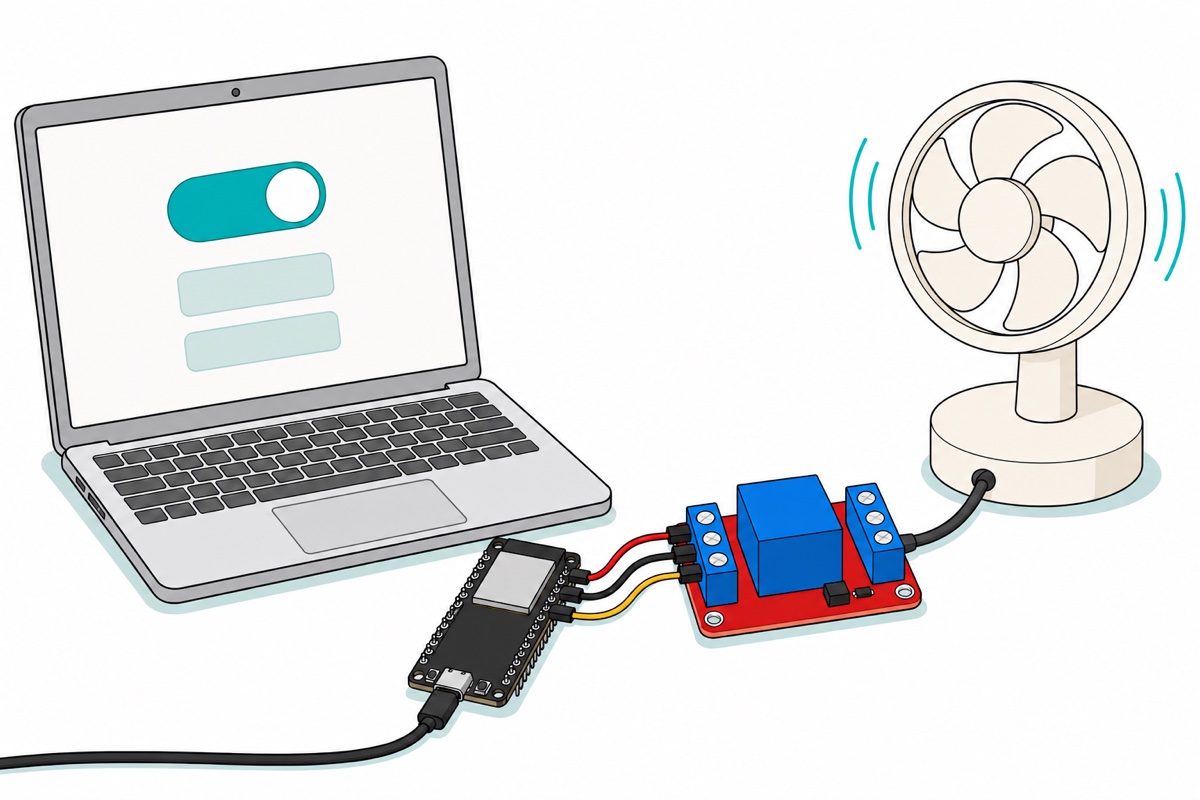
Once the board serves its own page, the rest is just more routes: a sensor reading beside the button, a second relay, a schedule that flips it at dusk. Want it switched by voice instead? Our offline voice-control relay drives the same module with no network at all.
Last updated August 2026. Stuck? Chat with us on WhatsApp.
