

Tutorials
L298N Motor Driver Arduino: Direction and Speed Control
Jun
On the L298N, direction and speed live on different pins. IN1 HIGH with IN2 LOW turns the motor one way, IN1 LOW with IN2 HIGH turns it the other, and analogWrite() on ENA sets how fast. The catch that stops most first builds: ENA ships with a black jumper cap fitted, so your speed command does nothing until it comes off.
What do IN1 and IN2 actually tell the L298N to do?
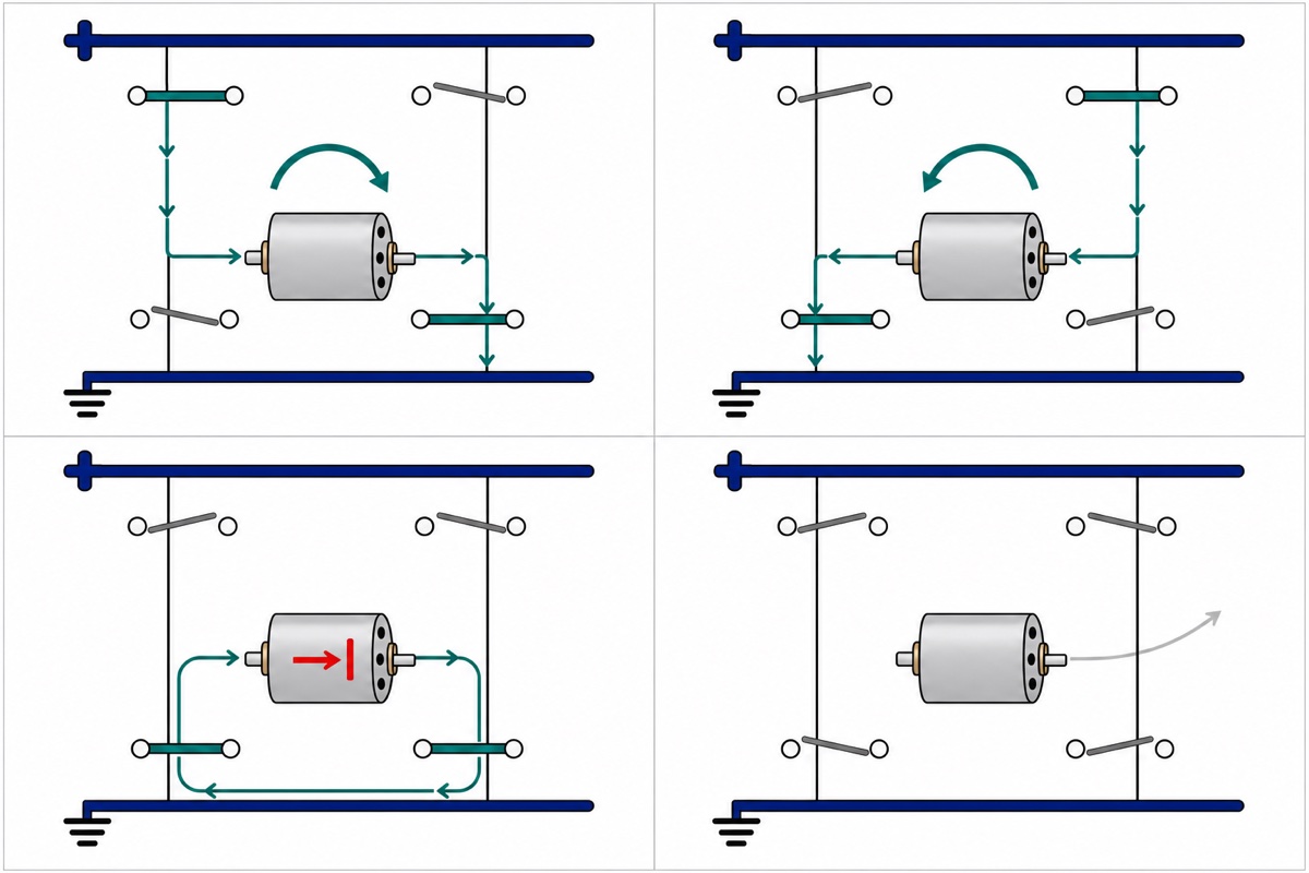
The L298N module is built around ST’s L298 dual full-bridge driver, and a full bridge is four switches arranged in an H around the motor. Close the top-left and bottom-right pair and current crosses the motor one way; close the other diagonal and it crosses the other way. The supply never changes polarity — only which way round the motor hangs across it. IN1 and IN2 are therefore two bits, and two bits have four states.
| ENA | IN1 | IN2 | What the motor does |
|---|---|---|---|
| HIGH | HIGH | LOW | Turns one way |
| HIGH | LOW | HIGH | Turns the other way |
| HIGH | LOW | LOW | Brake — fast stop |
| HIGH | HIGH | HIGH | Brake — fast stop |
| LOW | anything | anything | Coast — free-running stop |
Whenever IN1 and IN2 match, both ends of the motor are tied to the same rail, so the motor is shorted across itself — and a spinning motor is a generator. A generator into a short pushes current, that current makes torque, and that torque opposes the spin. So 00 and 11 both brake, and neither is “off”.
Off comes from the enable pin. Pull ENA low and all four transistors open at once. The winding’s stored current has no driven path left, so it flows backwards through the board’s flyback diodes into the supply, which opposes it and kills it almost at once — and with no current there is no braking torque, so the rotor freewheels down. ST’s own truth table calls this state “Free Running Motor Stop”. Brake is an input-pin state; coast is an enable-pin state. ENB, IN3 and IN4 repeat all of it for a second motor.
Parts list
 L298N Motor Driver Module Arduino Compatible Dual H Bridge Dual DC Motor Control Arduino Robotic Car
 DC Solar Motor DC 1.5V 3V 3.3V 5V Mini Round DC Motor For Arduino IOT Solar Project
 Arduino Uno Compatible SMD UNO R3 with Type B Cable - ATMEGA328P with CH340G-Microcontroller Project
 Sensor Shield V5.0 Arduino Uno R3 Shield For Arduino Protoype Application
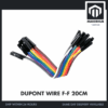 40pcs Dupont Wire 10cm 20cm 30cm for Breadboard DIY Experiment Jumper Wire Breadboard wire - DUPONT WIRE F-F 20CM
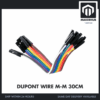 40pcs Dupont Wire 10cm 20cm 30cm for Breadboard DIY Experiment Jumper Wire Breadboard wire - DUPONT WIRE M-M 30CM
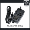 Power Supply Adapter DC Universal AC to DC Converter PSU 5V2A 5V3A 9V2A 12V2A - P.S. ADAPTOR (5V2A)
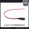 5.5x2.1mm DC Power Male Connector Plug Jack Adapter for Arduino DIY Electronics Projects - 5.5x2.1 DC CONNECTOR (F)
Optional: a multimeter
| Item | Price | Qty | |
|---|---|---|---|
 XL830L Digital Multimeter with backlight Portable Multimeter Electronics ProjectMULTIME XL830L Digital Multimeter with backlight Portable Multimeter Electronics ProjectMULTIME | RM25.95 |
Two five-second checks it makes easy: telling the enable pin from the +5V pin under each jumper cap, and reading the real voltage the bridge delivers to the motor.
Why does analogWrite() on ENA do nothing?
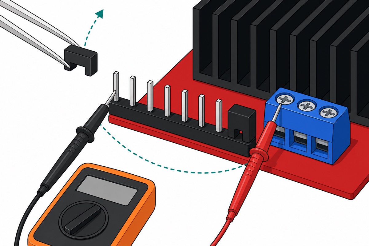
The L298N’s logic row is eight positions wide: a two-pin header at each end wearing a black shorting cap — ENA nearest the three-way screw terminal, ENB at the far end — with the four IN pins between. A cap joins its two pins, and a schematic teardown of this board states that the ENA and ENB jumpers “tie them high to the +5V power plane”. Enable is already held HIGH in hardware, so your PWM pin has nothing left to enable. Lift both caps off and keep them.
Then tell the two bared pins apart, because they look identical. Board unpowered, meter on continuity: hold one probe on the +5V screw terminal and touch the other to each pin. The one that beeps is the +5V side the cap was bridging to; its neighbour is the enable input, and that is where your jumper goes. Worth the ten seconds: land the wire on the +5V pin instead and the first time your sketch drives that Arduino pin LOW, you have shorted the board’s 5V rail to ground through the Arduino’s own output transistor.
The next thing people try is PWM on IN1 instead. That is a different control. PWM on ENA alternates drive and coast: each off-slice opens all four switches, the stored current freewheels through the board’s flyback diodes, and the rotor carries on under its own momentum. PWM on IN1 with IN2 held LOW alternates drive and brake, because IN1 going low makes both inputs match — every off-slice fights the rotor you just pushed. Reverse, and IN2 is HIGH, so the high slices become brake and the duty inverts. Speed belongs on the enable pin: it is the only pin whose meaning does not flip with direction.
How do you wire the L298N to an Arduino Uno?
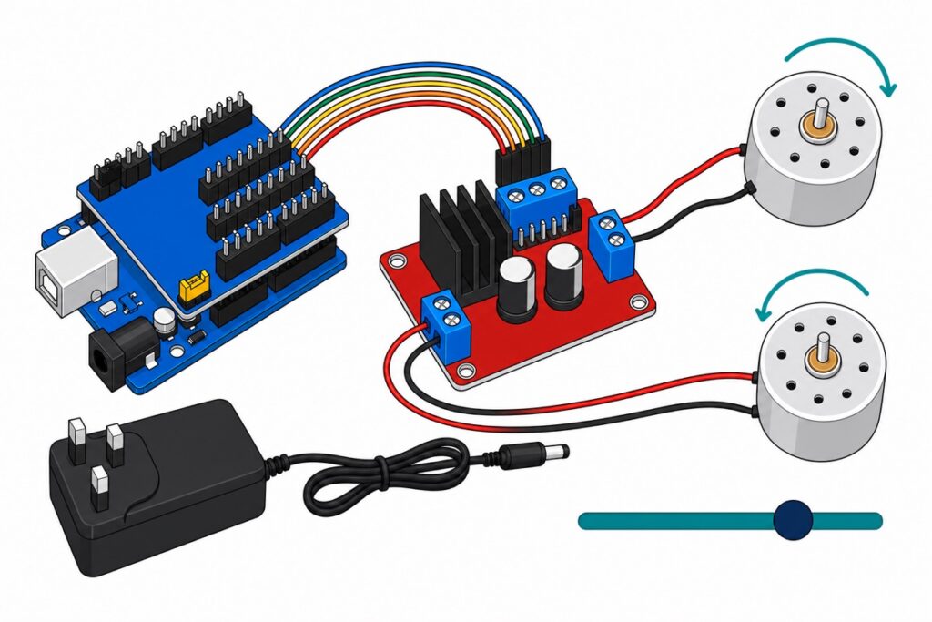
The L298N’s six control pins are male and stand straight up off the PCB — the Arduino Uno‘s headers are female, and those upright pins keep the module out of a breadboard too. The Sensor Shield V5.0 settles it: it presses down onto the Uno’s headers and re-presents every digital pin as a male S pin in a G/V/S triple, so plain female-to-female jumpers bridge male to male with nothing soldered. All six signals come off two neighbouring blocks, 11 10 9 8 and 7 6 5 4.
Three jumper caps come off the L298N before you wire anything: ENA and ENB, which you lifted in the section above, and the 5V jumper beside the three-way screw terminal, which gets its own section below. Do that third one now, because taking it off is what turns the +5V terminal from an output into an input — and feeding it from the Arduino while the cap is still on is what kills these boards.
| L298N | Goes to | Wire |
|---|---|---|
| ENA (cap removed) | S pin of column 10 → D10 | F-F jumper |
| IN1 | S pin of column 8 → D8 | F-F jumper |
| IN2 | S pin of column 7 → D7 | F-F jumper |
| ENB (cap removed) | S pin of column 9 → D9 | F-F jumper |
| IN3 | S pin of column 6 → D6 | F-F jumper |
| IN4 | S pin of column 5 → D5 | F-F jumper |
| +5V screw terminal | Any V pin on the shield → Uno 5V | F-F chained to M-M |
| GND screw terminal | Any G pin on the shield → Uno GND | F-F chained to M-M |
| +12V screw terminal | Barrel socket’s centre-pin lead | Bare tinned wire |
| GND screw terminal | Barrel socket’s other lead | Bare tinned wire |
| OUT1 / OUT2 | First motor’s red and black leads | Bare tinned wire |
| OUT3 / OUT4 | Second motor’s red and black leads | Bare tinned wire |
Two rows need a gender change. A screw terminal clamps bare metal and a female jumper hides its metal inside a shell, so push a male-to-male jumper into the free socket of the F-F lead and clamp its square pin under the screw. The GND screw takes two wires: the adaptor’s negative and that common-ground link, so tug both after tightening. Which motor lead goes into OUT1 and which into OUT2 is yours to pick: if the shaft turns the wrong way, swap those two leads or flip the boolean in the sketch.
The common-ground wire is not optional. HIGH only means something measured against a reference, so until the Uno and the L298N share a ground the module has no fixed idea what 5V on IN1 is — a driver that ignores the Arduino is usually this, not a dead board. Notice what that wire does not carry: motor current returns to the adaptor through the GND terminal, never through the Uno. These motors draw 12mA each at their rated 3V, but a stalled one draws many times that, and the Uno’s 5V pin is not where you want to find out.
Safety, none of it fussiness. Everything here is low-voltage DC; the 5V adaptor is a sealed unit you never open. Buzz the barrel socket pigtail before connecting it — continuity from the socket’s centre pin finds the positive lead, and this adaptor is centre-positive. Never pull a motor lead with the supply live: breaking current in a coil makes a voltage spike, and flyback diodes only protect an intact loop. The heatsink barely warms at these currents, but on a motor pulling amps it gets hot enough to hurt, so look before you grab it.
If you would rather see the board wired up and the motors actually turning before you commit your own screws, DroneBot Workshop’s L298N build covers this hardware on camera:
Why must the 5V jumper come off on a 5V build?
The L298N carries a third jumper, a separate two-pin cap beside the three-way screw terminal. Fitted, it feeds the motor supply into the on-board 78M05 regulator, which makes the logic 5V and hands it out on the +5V terminal — perfect on a 12V rail, impossible on a 5V one. A 78M05 needs roughly two volts of headroom, so from 5V in it produces something nearer 3V, and the L298’s logic supply pin is specified with a 4.5V minimum. Below that, ST guarantees nothing about how the chip reads IN1 or ENA — and it does not fail cleanly, because the motors are pulling on the very rail the regulator is working from, so every load surge drags the logic supply down with them. It behaves exactly like a bug in your sketch.
Pull the jumper and the same teardown says the +5V terminal “becomes an input port to accept external power”. Feed it a real 5V from the Uno — running on USB here — through any V pin on the shield, and the logic supply sits where the datasheet wants it. The shield’s yellow SEL jumper stays fitted exactly as it ships: that link is what ties its V pins to the Uno’s 5V.
Leave the L298N’s own 5V jumper fitted and feed that terminal and you have wired the Uno’s 5V straight onto the 78M05’s output pin: two regulators holding one node at slightly different voltages, the stronger one pushing current into the weaker for as long as they are joined, and neither built to absorb it. That is the usual way these boards die.
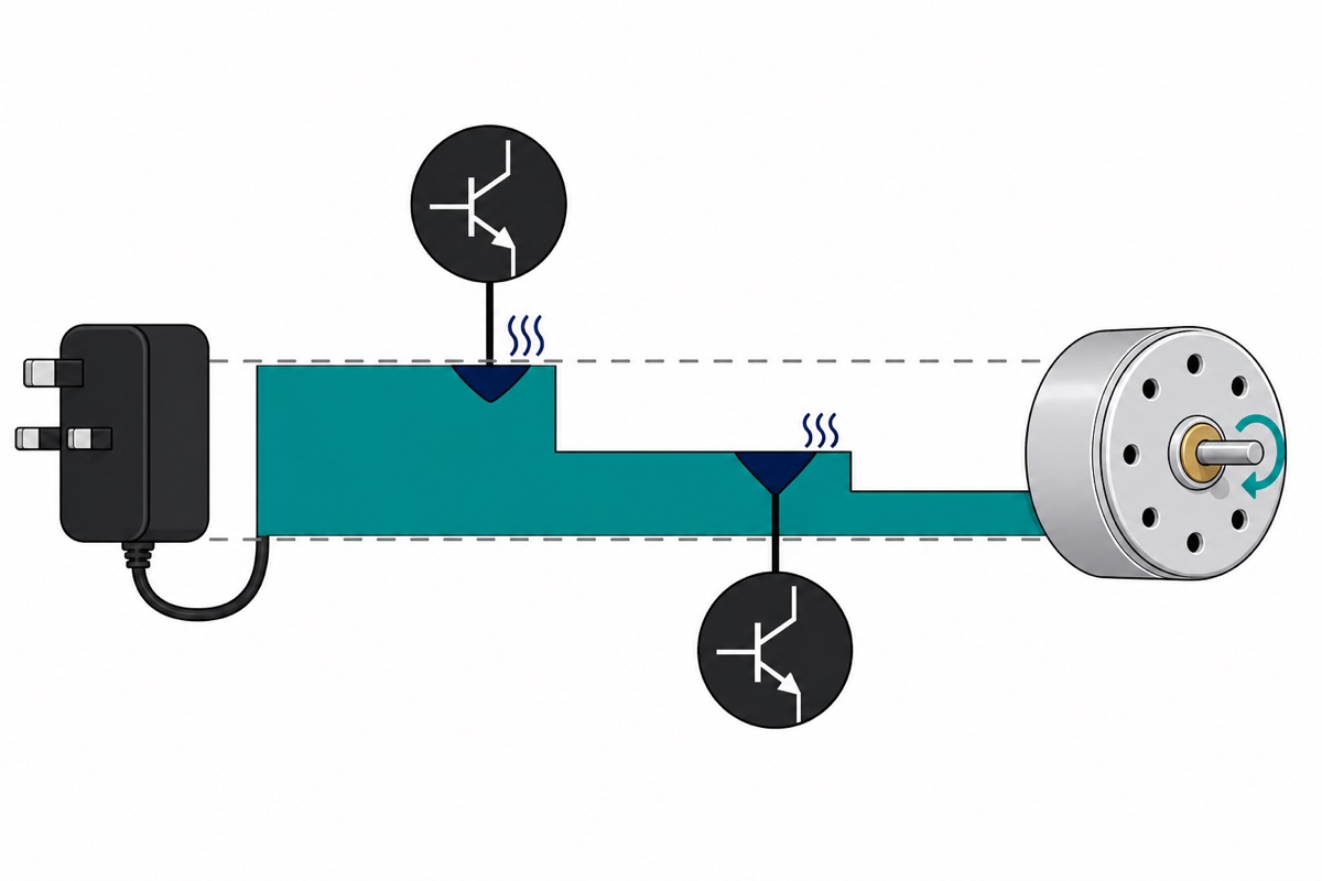
Why does the L298N lose about two volts before the motor?
The L298’s outputs are Darlington pairs — two bipolar transistors stacked for current gain — and a Darlington cannot pull its output all the way to its rail. Current in an H-bridge passes through two of them in series, one sourcing from the supply and one sinking to ground, so you pay the toll twice. ST’s numbers at 1A: 1.35V typical sourcing, 1.2V typical sinking, and a Total Drop row whose minimum is 1.80V, with a 3.2V maximum at 1A and 4.9V at 2A. Read that minimum column again — even at its best, at 1A this chip keeps 1.8V for itself.
Small motors draw far less and the drop falls with current, but never to zero: the current still climbs through base-emitter junctions that cost their fraction of a volt however little flows. Budget roughly 1.5–2V lost inside the bridge at hobby currents. That is why L298N builds so often feel weak.
So: choose a supply about two volts above the voltage you want at the motor. Ours is rated 1.5V to 5V, 3V nominal, and a 5V adaptor lands it near 3.5V — right on its rating. A 9V supply would put about 7.5V across a motor whose ceiling is 5V; bigger is not safer here, it is how windings cook. Already own a 12V brick? Dial it down with an LM2596 buck converter. And measure it on your own board: with a motor running at full duty, read DC volts from the +12V terminal to GND, then across OUT1 and OUT2. The difference is what the bridge kept for itself (our multimeter guide covers the settings).
What does the Arduino code for the L298N look like?
The Uno’s analogWrite() needs no library, and D10 and D9 are deliberate picks: both sit on Timer1 at roughly 490 Hz, so the two channels behave identically. Pins 5 and 6 run near 980 Hz on the timer that also drives millis(), which skews their duty cycles — so they carry plain direction outputs here.
// L298N dual H-bridge: direction lives on the IN pins, speed on the EN pins.
// Pull the black shorting caps off ENA and ENB first. While a cap is fitted
// the enable pin is tied to the board's +5V plane and analogWrite() on it
// has nothing left to switch - the motor just runs flat out.

const int ENA = 10;   // PWM pin, Timer1, ~490 Hz
const int IN1 = 8;
const int IN2 = 7;

const int ENB = 9;    // PWM pin, Timer1 as well, so both channels match
const int IN3 = 6;
const int IN4 = 5;

// A 5V rail loses roughly 1.5V inside the bridge, so full duty puts about
// 3.5V across the motor. This motor's own minimum is 1.5V, and 1.5 / 3.5
// of full scale is 255 * 1.5 / 3.5 = 109 counts. Below about 110 the
// average falls under that minimum and the motor tends to sit and buzz.
const int MIN_DUTY = 110;
const int MAX_DUTY = 255;
const int KICK     = 200;   // brief shove to break stiction from rest

// EN LOW opens all four transistors of that bridge at once: both motor
// terminals float, no current can circulate, and the rotor freewheels down.
void coast(int en) {
  digitalWrite(en, LOW);
}

// Both IN pins at the same level, with the bridge enabled, ties both motor
// terminals to the same rail. A spinning motor is a generator, and here it
// is a generator into its own short - that current is braking torque.
void brake(int en, int inA, int inB) {
  digitalWrite(inA, LOW);
  digitalWrite(inB, LOW);
  digitalWrite(en, HIGH);
}

// 1,0 is one direction and 0,1 the other. Speed never touches these pins.
void drive(int en, int inA, int inB, bool forward, int duty) {
  digitalWrite(inA, forward ? HIGH : LOW);
  digitalWrite(inB, forward ? LOW  : HIGH);
  analogWrite(en, constrain(duty, 0, MAX_DUTY));
}

void ramp(int en, int inA, int inB, bool forward, int from, int to) {
  int stepDir = (to >= from) ? 1 : -1;
  for (int duty = from; duty != to; duty += stepDir) {
    drive(en, inA, inB, forward, duty);
    delay(15);
  }
  drive(en, inA, inB, forward, to);
}

void setup() {
  Serial.begin(9600);

  const int pins[] = {ENA, IN1, IN2, ENB, IN3, IN4};
  for (unsigned int i = 0; i < sizeof(pins) / sizeof(pins[0]); i++) {
    pinMode(pins[i], OUTPUT);
    // The L298 datasheet asks for Enable LOW before the motor supply comes
    // up and before it goes down. Starting everything low honours that.
    digitalWrite(pins[i], LOW);
  }

  Serial.println(F("L298N ready: channel A on D10/D8/D7, channel B on D9/D6/D5"));
}

void loop() {
  Serial.println(F("A forward - kick, then settle to the slowest duty that still turns"));
  drive(ENA, IN1, IN2, true, KICK);
  delay(200);
  ramp(ENA, IN1, IN2, true, KICK, MIN_DUTY);
  delay(1500);

  Serial.println(F("A forward - ramp up to full"));
  ramp(ENA, IN1, IN2, true, MIN_DUTY, MAX_DUTY);
  delay(1500);

  Serial.println(F("A brake - the shaft stops dead"));
  brake(ENA, IN1, IN2);
  delay(1200);

  Serial.println(F("A reverse at full, B forward at half - both bridges at once"));
  drive(ENA, IN1, IN2, false, MAX_DUTY);
  drive(ENB, IN3, IN4, true, 128);
  delay(2000);

  Serial.println(F("A and B coast - both shafts freewheel down"));
  coast(ENA);
  coast(ENB);
  delay(2500);
}
Compare the brake against the coast that closes each loop: brake halts the shaft inside a fraction of a turn, coast lets it wind down over a second or two.
Common mistakes we see from real customers
The pattern that reaches us most often with the L298N is a motor stuck at one speed — sketch right, D10 wire right, enable cap still fitted. Close behind is a driver that ignores the Arduino entirely, which is almost always a missing common ground and not a dead board.
Then the motor that hums without turning at low numbers: below roughly analogWrite(110) here the average sits under the motor’s own 1.5V minimum, so a brief kick then a drop back is the fix, not a bigger supply. And the expensive one — a 12V adaptor bought because the terminal is silkscreened +12V. That label names the common case, not a ceiling and not an instruction: the pin is simply the motor supply input — it takes anything from 5V to 35V — and the number that decides your adaptor is your motor’s rating plus the bridge drop.
FAQ
Why does my L298N run at full speed no matter what I write to ENA?
The black shorting cap over ENA is still fitted. It bridges the enable pin to the board’s +5V plane, holding the bridge permanently on, so analogWrite() has nothing left to switch. Pull it off, and off ENB too if you use the second channel.
Can I PWM IN1 instead of ENA?
It moves the motor, but it is a different control: IN1 going low while IN2 is low makes both inputs match, which brakes rather than coasts. It also inverts when you reverse, because with IN2 HIGH the high slices become brake.
How much voltage does the L298N lose?
Current passes through two Darlington stages in series, one sourcing and one sinking. ST specifies the total drop as a 1.80V minimum and 3.2V maximum at 1A. At hobby milliamps it is nearer 1.5–2V, so size the supply about two volts above the motor’s rating.
Should I remove the 5V jumper on the module?
Remove it whenever the motor supply is below about 7V: the 78M05 cannot make 5V out of a 5V input, and the L298’s logic supply needs at least 4.5V. The +5V terminal then becomes an input you feed from the Arduino. Leave it fitted for a 9V or 12V rail, but not much above that: the 78M05 burns off every volt of the difference as heat, so a 24V rail with 200mA drawn from that terminal is nearly four watts inside a small surface-mount regulator that has no heatsink of its own.
Can the L298N hold a motor at an exact speed?
No — analogWrite() sets duty cycle, not RPM, so the motor slows under load and nothing tells the Arduino. Closing that loop needs a motor that reports its own rotation, such as our TT gear motor with encoder, whose six-way JST tail wants a matching header rather than jumper wires. On drivers: one direction needs only a single MOSFET, unipolar steppers want a Darlington array, and this board is the hub inside our line follower guide.
Last updated August 2026. Stuck? Chat with us on WhatsApp.

Pingback: Stepper vs Servo vs DC Motor: Which for Your Arduino?
Pingback: Small 5V DC Fan or Fan Module? How to Choose and Drive It