

Tutorials
IRF520 MOSFET Module: Why Your Arduino Fan Spins Then Stops
May
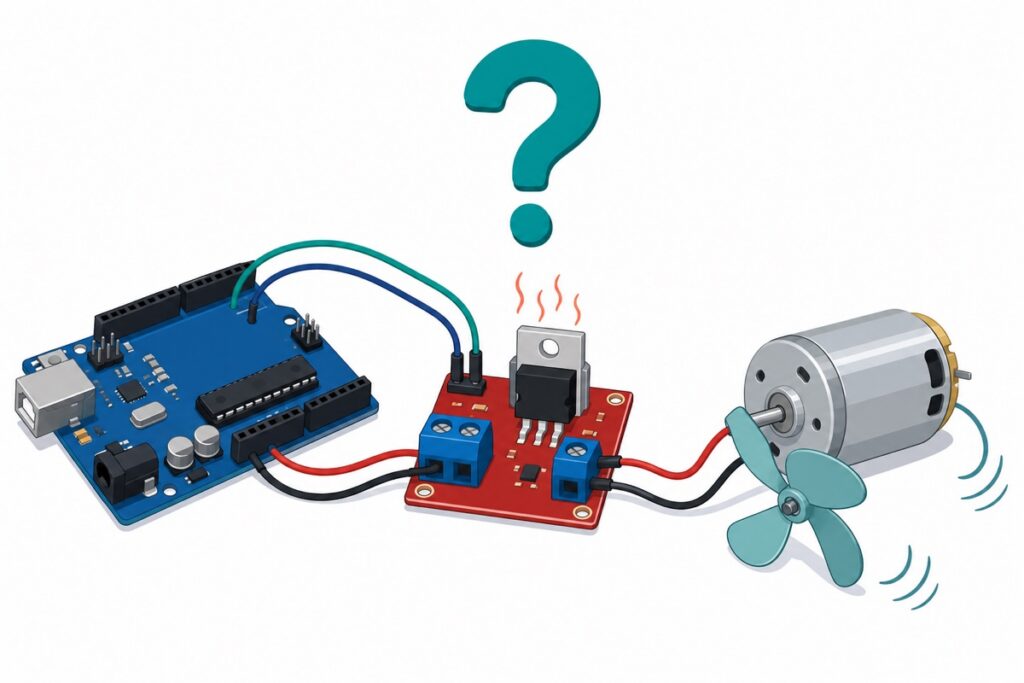
A fan that spins then stops on the IRF520 MOSFET module usually means the transistor is only half on. The IRF520 needs about 10 V on its gate to switch fully on — an Arduino’s 5 V only partially opens it, so voltage is lost as heat and the motor stalls. Bypassing the module works because the fan sees full voltage.
Why does the fan spin and then stop on the IRF520 module?
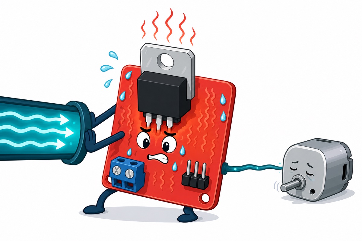
The IRF520 on this module is a standard-gate power MOSFET, designed for gate drivers that supply 10 V or more. At a 5 V gate it is only partially enhanced: instead of a closed switch, it behaves like a resistor of half an ohm to several ohms in series with your fan.
That resistance explains the symptom: a fan draws little current at low speed, so it starts to spin — but as it accelerates its demand climbs, the drop across the half-open MOSFET grows, and the motor voltage sags until the fan stalls. The heat is the evidence, not the trigger: the missing volts were being burned in the transistor from the first moment. Bypassing proves the supply and fan are healthy — gate drive is the culprit.
None of this makes the module junk — within its envelope it is genuinely useful, and this guide maps that envelope honestly.
Parts list
 Arduino Uno Compatible SMD UNO R3 with Type B Cable - ATMEGA328P with CH340G-Microcontroller Project
 IRF520 MOSFET Driver Module PWM Output Power Control for Arduino Raspberry Pi DC Motor Control
 3V 140 DC Motor Small Electric Motor for DIY Projects Arduino Robotics RC Car Robot Smart Car
What does the IRF520’s gate threshold voltage actually mean?
The IRF520’s datasheet lists a gate threshold voltage of 2.0–4.0 V, measured at a drain current of just 250 µA. Vgs(th) is where the transistor barely begins to conduct, not where it is usefully on — the most misunderstood number on any MOSFET datasheet. “Threshold 2–4 V, my Arduino outputs 5 V, so we’re fine” is the reasoning behind this exact failure.
The number that matters is the on-resistance condition: the IRF520’s famous 0.27 Ω figure is specified at Vgs = 10 V, and every headline rating — the 9.2 A drain current, the low loss — assumes that gate voltage. At 5 V you get a compromised, hotter version of the part; at 3.3 V, almost nothing.
| Gate voltage (Vgs) | What the datasheet says | What your motor experiences |
|---|---|---|
| 2–4 V (threshold) | Conduction just begins — 250 µA test current | Nothing useful; a twitch at best |
| 3.3 V (ESP32 pin) | Barely past threshold on many units | Weak, unreliable, unit-to-unit lottery |
| 5 V (Uno pin) | Typical transfer curve shows about 2 A — far less on high-threshold units | Small loads work; volts are lost as heat |
| 10 V (spec condition) | 0.27 Ω max on-resistance, 9.2 A rating applies | The full performance the part is sold on |

How much current can the module really switch at 5 V?
The IRF520 module’s listings usually print “0–24 V, up to 5 A” — numbers that describe the screw terminals and the transistor’s outer limits, not what a 5 V gate delivers. Careful suppliers derate it plainly: the IRF520 is not fully 5 V-logic compatible, and at 3.3 V logic the sensible limit is about 1 A.
At a 5 V gate, treat roughly an amp of continuous current as the honest budget. The datasheet’s typical transfer curve shows about 2 A at a 5 V gate — but that is a typical-part figure, and with a 2.0–4.0 V threshold spread a high-threshold unit delivers far less; budgeting an amp keeps the worst unit in the bag comfortable. Below that it is a fine little switch; push toward the printed 5 A and the FET must dissipate watts it was never given the gate voltage to avoid.
Does the IRF520 module include a flyback diode?
The IRF520 module exists in several revisions: some include a protection diode across the load, many carry only the MOSFET, two resistors and an indicator LED. Check your board, not a listing photo: unpowered and disconnected, probe the load terminals (V+ and V−) both ways in diode mode — about 0.2–0.7 V one way means a diode is fitted (Schottky types read at the low end); open both ways means none.
Either way, fit an external flyback diode on any brushed motor or fan — a basic 1N4007-class rectifier across the motor terminals, striped end (cathode) toward V+. It gives the motor’s switch-off voltage spike a safe loop instead of letting it hammer the transistor — the same physics as the relay-coil diode in our relay module safety guide.
How do you wire the IRF520 module to an Arduino Uno?
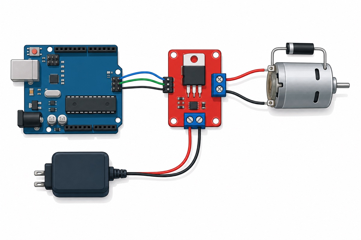
The IRF520 module has three zones: the 3-pin header (SIG, VCC, GND) for the control signal, one screw-terminal pair for the load supply, and one for the load — the silkscreen on your batch tells you which is which. This wiring assumes a plain two-wire DC fan or motor; a four-wire computer fan wants PWM on its dedicated control wire.
| Module terminal | Connects to | Note |
|---|---|---|
| SIG | Uno D9 | PWM-capable pin for speed control |
| VCC | Uno 5V | Header supply for the indicator circuit |
| GND (header) | Uno GND | Must be shared — no common ground, no switching |
| Supply pair (VIN / GND) | Load supply + / − | 5V bench supply for the small 140 motor |
| Load pair (V+ / V−) | Motor red / black | Flyback diode across the motor, stripe toward V+ |
The little 3V 140 motor is a perfect first load, well inside the budget; since it is a 3 V motor on a 5 V supply, the sketch caps the PWM duty to keep its effective voltage sensible. The soft-start ramp avoids the stall-current surge that can drag a shared supply down and reset the Uno.
// IRF520 module + Arduino Uno — PWM motor control with soft-start
// Control: SIG -> D9, VCC -> 5V, GND -> GND (shared with load supply GND)
// Load: small DC motor on V+ / V-, flyback diode across the motor (stripe to V+)

const int MOTOR_PIN = 9;    // PWM pin
const int MAX_PWM   = 150;  // cap for a 3V motor on a 5V supply (150/255 x 5V = ~2.9V)
                            // use 255 only if your motor is rated for the supply voltage

void setup() {
  pinMode(MOTOR_PIN, OUTPUT);
  // Soft-start: ramp up gently so the stall-current surge
  // does not drag the supply down and brown out the board
  for (int duty = 0; duty <= MAX_PWM; duty++) {
    analogWrite(MOTOR_PIN, duty);
    delay(15);               // about 2 seconds from stopped to cruise
  }
}

void loop() {
  analogWrite(MOTOR_PIN, MAX_PWM);   // cruise
  delay(4000);
  for (int duty = MAX_PWM; duty >= 0; duty--) {  // gentle stop
    analogWrite(MOTOR_PIN, duty);
    delay(10);
  }
  delay(2000);
  for (int duty = 0; duty <= MAX_PWM; duty++) {  // gentle restart
    analogWrite(MOTOR_PIN, duty);
    delay(15);
  }
}
To see the module switching a real load before wiring your own:
What if you have a 3.3 V board or a bigger load?
The IRF520 module is the wrong part to drive directly from an ESP32 or any 3.3 V board — 3.3 V barely clears the threshold lottery, and our ESP32 vs ESP8266 vs Uno comparison explains that logic-level divide. The textbook fix is a logic-level MOSFET (IRLZ44N-class), which reaches its rated on-resistance at a 5 V gate.
For 3.3 V boards and anything beyond the one-amp budget, a relay module is the honest answer: its opto input triggers happily from 3.3 V and its contacts don’t care about gate physics — exactly how our automatic plant watering build switches its pump. If you want PWM speed control, keep the IRF520 module and drive it from a 5 V-logic board like the Uno.
Common mistakes we see from real customers
The mystery this article is named after. A customer reported, in effect: “IRF520 fan spins then stops (bypass ok)”. The bypass test was the smart move — it cleared the fan and the supply. The fix: the fan drew more than the module’s 5 V-gate budget, so it moved to the relay path.
Driving SIG from a 3.3 V board. The motor twitches, hums, or works on one module and not its twin — threshold-lottery behaviour, not a defective board. Use a 5 V-logic board or a relay module.
No shared ground. A separate load supply with the header GND left unconnected to the Uno gives erratic, half-working switching. Gate voltage is measured against module ground; join them.
Budgeting for the printed 5 A. That figure assumes gate drive the Arduino cannot provide — at a 5 V gate, plan around an amp and watch the heatsink.
Skipping the flyback diode. It may run for weeks without one, but every switch-off spike is a gamble a one-component diode eliminates.
FAQ
Can I use the IRF520 module with an ESP32 or ESP8266?
Not directly. At a 3.3 V gate the IRF520 sits barely past its threshold, so behaviour varies unit to unit and current capability collapses. Use a relay module (its opto input works at 3.3 V) or drive the module from a 5 V-logic board instead.
Why does my IRF520 module get hot even with a small motor?
At a 5 V gate the transistor is only partially on, so it drops real voltage and dissipates it as heat. Some warmth is normal; too hot to touch means the load is beyond the 5 V-gate budget — reduce the current or switch to a relay.
Can the IRF520 module do PWM speed control?
Yes — that is its best trick, something a plain relay cannot do. Use analogWrite on a PWM pin; on an Uno, pin D9 runs at about 490 Hz, and a faint motor whine at that frequency is normal.
Do I really need the flyback diode for a small fan or motor?
Fit it. A brushed motor kicks back a voltage spike at every switch-off, and PWM means hundreds of switch-offs per second on an Uno. The IRF520 often survives without one, but a single rectifier diode turns “often survives” into “protected”.
Is the IRF520 module a bad product?
No — it is a good board often listed with optimistic numbers. Inside its envelope (5 V signal, around an amp, PWM control, flyback diode on motors) it is cheap, simple and reliable. Outside that envelope, pick the relay path instead.
Last updated August 2026. Stuck? Chat with us on WhatsApp.

Pingback: Vibration Motor vs Vibration Sensor for Arduino