

Tutorials
Small 5V DC Fan or Fan Module? How to Choose and Drive It
Sep
Match the fan to the supply you already have, then switch it with a transistor, a driver module or a relay — never straight off an Arduino output pin. A bare 5V or 12V case fan is two wires and spins the moment it has power. A fan module is the other thing entirely: a bare motor sitting on a driver chip, so your pin only has to command the chip while the chip carries the motor’s current.
What is the difference between a DC cooling fan and a “fan module”?
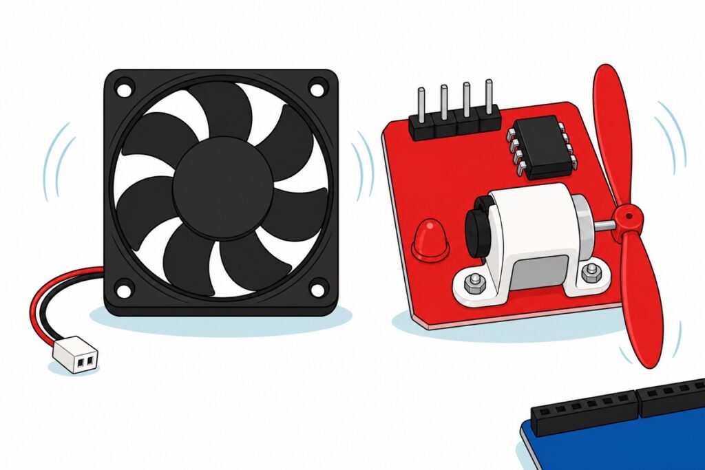
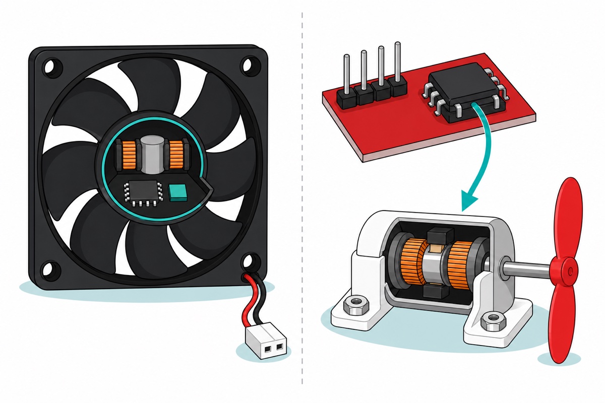
The 4010 case fan is a sealed brushless unit: a black 40 × 40 × 10 mm frame, a red-and-black lead, a small white two-pin plug. Two wires is all it needs because the rest lives in the hub — a driver chip and a Hall sensor that tracks the rotor and switches the coils in step with it. It commutates itself, which is also why it arrives with its speed already decided: there is no control input on those two wires, so anything you do to the supply you also do to the driver chip inside.
The L9110 fan module is built the other way round: a red board marked “Fan Motor” carrying a socketed eight-pin L9110 H-bridge, a small white brushed motor under a bracket, and a red propeller you push onto the shaft. That motor is bare — brushes and a commutator, no electronics — so the chip is the product. Four pins marked GND, VCC, INA and INB hand the job to your board: drive one IN pin high and it turns, the other and it turns back.
Want air pushed through a project box? Case fan plus a switch. Want a fan your code can start, throttle and reverse? Module.
Parts for the worked example — a temperature-triggered 5V fan, no soldering
 Arduino Uno Compatible SMD UNO R3 with Type B Cable - ATMEGA328P with CH340G-Microcontroller Project
 DC Cooling Fan 5V/12V Brushless Small Fan for 3D Printer DIY Projects Electronics Cooling - 4010 FAN (5V)
 Relay Module 3.3V 5V 12V 1/2/4/8 Ways Optocoupler Trigger Relay Module 1 2 4 8 Channel Relay Module - 5V RELAY MODULE(1WAY)
 DHT 11 DHT 22 Temperature and Humidity Sensor DHT22 High Sensitivity Sensor DHT11 For Aduino IOT - DHT11 SENSOR
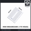 MB102 Breadboard 170 400 830 Holes Breadboard Donut Board Arduino Prototype Multi Color - MINI BREADBOARD 170 HOLES (WHITE)
 40pcs Dupont Wire 10cm 20cm 30cm for Breadboard DIY Experiment Jumper Wire Breadboard wire - DUPONT WIRE M-M 20CM
The other lanes — pick what your build actually needs
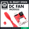 DIY Fan Module DC Small Motor Fan for Fire Fighting Project L9110
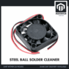 DC Cooling Fan 5V/12V Brushless Small Fan for 3D Printer DIY Projects Electronics Cooling - 4010 FAN (12V)
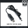 USB To 9V DC Jack Cable 5.5 x 2.1 mm 5V 9V DC Power USB Cable Connector Jack - USB TO 12V DC JACK
 5.5x2.1mm DC Power Male Connector Plug Jack Adapter for Arduino DIY Electronics Projects - 5.5x2.1 DC CONNECTOR (F)
 40pcs Dupont Wire 10cm 20cm 30cm for Breadboard DIY Experiment Jumper Wire Breadboard wire - DUPONT WIRE M-F 20CM
 IRF520 MOSFET Driver Module PWM Output Power Control for Arduino Raspberry Pi DC Motor Control
These are alternatives, not extras to the list above. The L9110 fan module is the all-in-one lane: motor, propeller and driver on one board. The 4010 12V fan plus the USB-to-12V boost cable and a female barrel-jack pigtail is the 12V lane, whose bare wire ends clamp straight into the relay's screw terminals. The M-F jumpers suit a build without a breadboard, and the IRF520 module is the MOSFET lane for real PWM speed control on a bare fan.
Why can a 5V fan not hang off an Arduino output pin?
The ATmega328P on an Uno-compatible board is generous about voltage and mean about current. Its datasheet caps a pin at 40 mA absolute, but design to 20 mA, because that is as far as the output-voltage tables go. Past it the chip stops guaranteeing a pin driven high is near 5V: the pin’s output transistor has resistance, and the harder you pull the more of your supply it eats. The pin goes soft long before it goes bang.
Now look at what a motor asks at switch-on. The rotor is not moving, so it generates no back-EMF to oppose the supply and the only thing limiting current is the bare resistance of the winding. That surge — repeated whenever a blade jams — is a large multiple of a running current already in the wrong order of magnitude for 20 mA. A 40 mm fan is a motor. If you would rather have the figure for the fan in your hand than a rule of thumb, put a multimeter in series with it in DC current mode and read it while it spins freely; start and stall draw is several times that, and the stall figure is the one a pin would have to survive.
The flyback-diode advice people quote here is true of one of these parts, not the other. A brushed motor’s winding, or a relay’s coil, is an inductor: interrupt its current and the collapsing field makes the coil produce whatever voltage keeps that current flowing — a spike above your supply, in the wrong direction, which is what punctures a transistor. A diode across the coil gives it a harmless loop to die in, and the L9110 and relay modules carry theirs on board. A brushless fan is not that kind of load: its own driver absorbs that switching internally. It still may not touch a pin — for the current, not the spike.
What are the three honest ways to switch a fan?
A MOSFET low-side switch is the cheapest lane. The transistor — MOSFET or bipolar — sits between the fan’s negative wire and ground; the pin drives its gate or base, which costs a small fraction of the load current, and the fan’s current flows through the transistor to ground instead of the chip. It is called low-side because the switch sits in the ground end, and that is not an arbitrary choice: an N-channel MOSFET conducts when its gate is a few volts above its source, and down there the source is ground, so a 5V pin can reach it. Put the same part in the positive wire and the source rides up at the supply, the gate would have to go above the supply to turn on, and you are into charge pumps or a P-channel part. The IRF520 module is that lane packaged, with one failure mode our IRF520 guide takes apart: a gate that never gets enough voltage from 5V logic to turn fully on, so the fan spins up and dies.
The L9110 fan module is the only lane where fan and driver arrive together. The L9110 is a single H-bridge — one motor, not two — rated 800 mA continuous per channel over a 2.5–12V supply, with kick-back diodes built in and two control pins instead of one — which is where reverse comes from, as our L298N guide shows.
A relay earns its place when the fan’s supply and your logic are different voltages. Our 1-way 5V relay module uses an SRD-05VDC-SL-C stamped 10A 30VDC, and its coil side and contact side share no metal: the IN terminal only lights the optocoupler you can see on the red board, the module’s own transistor pulls the coil in from DC+, and the contacts that coil throws are moving metal fingers joined to none of it — which is how they can pass a 12V circuit that knows nothing about your board; our relay guide goes deeper.
| Lane | What carries the fan current | Speed control | Fan supply may differ from logic | Our part |
|---|---|---|---|---|
| Transistor / MOSFET low-side switch | The transistor, to ground | Yes — real PWM | Yes, if you join the grounds | IRF520 module |
| H-bridge driver module | The L9110 chip | Yes, plus reverse | Only within the chip’s 2.5–12V range | L9110 fan module |
| Relay | Mechanical contacts | No — on/off only | Yes, completely isolated | 5V relay module |
A transistor passing a load current, watched rather than drawn:
How do you wire the L9110 fan module?
The L9110 fan module takes four wires and nothing else. GND and VCC go to your board’s ground and 5V, and that single VCC feeds both the chip’s logic and the motor it drives — so whatever powers the module has to carry the motor as well, the same rule as the fan: if the board resets when the propeller starts, give the module its own supply and join the grounds. INA and INB go to two digital pins, and the chip reads them as a pair.
| INA | INB | What the propeller does |
|---|---|---|
| LOW | LOW | Stops |
| HIGH | LOW | Turns one way |
| LOW | HIGH | Turns the other way |
| HIGH | HIGH | Stops — same as both LOW |
Both inputs at the same level stop the motor, and they stop it the same way: the H-bridge ties the motor’s two terminals together, so a still-turning armature generates into its own short and brakes instead of freewheeling. Speed comes from the same two pins — hold one LOW and analogWrite the other, and the winding’s inductance averages the bursts into a lower steady current. On an Uno only the six pins marked with a tilde (3, 5, 6, 9, 10 and 11) produce real PWM; analogWrite anywhere else gives you full on or full off.
One honest limit on this module: the red propeller is a press-fit part you push onto the shaft yourself, and the result is an open blade on a bare board. It moves air across a bench and reverses on command, but it does not bolt into the wall of a project box the way a square case fan does. If the job is cooling an enclosure, the case fan is still the part — the module is for a fan your code owns.
Why does PWM make a cheap fan buzz or refuse to start?
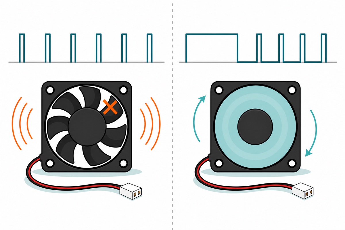
A brushed motor takes PWM without complaint. Chopping its supply lowers the average voltage across the winding, the winding’s own inductance smooths the pulses into a steadyish current, and the motor slows. That is what the L9110 module does when you analogWrite to an IN pin.
A two-wire brushless case fan misbehaves because chopping its supply chops the driver chip inside the hub as well. Every off-period that chip’s rail collapses, it loses the Hall reading and its place in the commutation sequence, and starts again on the next pulse. At low duty it never gets a long enough run to bring the rotor round, so the coils are merely kicked at the PWM rate and the fan stands still, humming at your PWM frequency. Every fan has a duty floor below which it will not run.
Kick-starting is the working answer. Command full duty for a few hundred milliseconds so the rotor is moving and the driver gets a clean spell to find commutation, then drop to the duty you want — a turning rotor needs far less torque than a stopped one needs to break away. Hard-code that floor as the minimum your code may command: a fan told to run at 15% and silently stalled is a fan you believe is cooling something.
The module’s brushed motor has none of this to fight:
Should you buy the 5V fan or the 12V one?
The 4010 case fan is sold in a 5V and a 12V version, and the one to buy is the voltage of the supply already in your project, not the fan you liked. A brushless fan’s driver has an undervoltage floor below which it cannot commutate, so a 12V fan fed 5V twitches, crawls or does nothing — and that is not a fault. The other direction is worse: a 5V part on 12V does not run fast, it cooks.
On USB, the 4010 5V fan is the answer. With a 12V brick, take the 12V fan and keep the board on its own 5V; with only USB, the boost cable and barrel pigtail above make a 12V pair of bare wires. Plug sizes and polarity are the subject of our DC supply guide.
Frame size is a separate decision. Swept area grows with the square of the diameter while noise climbs steeply with blade tip speed, so a bigger frame moves the same air more slowly and quietly. Take the biggest your hole allows.
| Frame | 5V | 12V | Suits |
|---|---|---|---|
| 40 × 40 × 10 mm | 4010 5V | 4010 12V | Small project boxes, 3D-printer electronics bays, tight lids |
| 60 × 60 × 10 mm | 6010 5V | 6010 12V | Bigger enclosures, where the extra hole is affordable and quiet matters |
Fitting the fan has two rules worth knowing before you drill. An axial fan draws air in through its open blade face and pushes it out of the side where the hub is carried on struts — the side the label is on — so a fan bolted in back to front will faithfully blow warm air back into the box. And a fan on its own does nothing in a sealed enclosure: air can only leave as fast as it gets in, so cut a second opening at the far end, high if the fan is low, and let the fan sweep the length of the case instead of pushing against a closed wall. The four corner holes are ø4 mm and sit on a 32 mm square pitch for a 40 mm frame, 50 mm for a 60 mm one, per Sunon’s dimensional drawings — M3 screws pass through them with room to spare, and those are the numbers to mark your panel with before the fan even arrives.
How do you build a temperature-triggered fan?
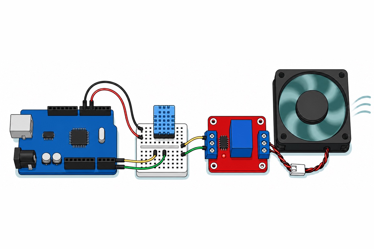
The DHT11 sensor reads air temperature, the Uno decides, and the relay module breaks the fan’s red wire. Nothing is soldered: both relay terminal blocks are screw clamps, and the fan’s white plug takes male jumper pins. The relay is not here for its isolation — sensor, board and fan all run on the same 5V — it is here because a thermostat only ever needs on or off, and a screw-terminal relay is the one lane that gets there with no soldering and no transistor to size. Move to the MOSFET lane the day you want the fan quieter rather than off.
One detail decides the layout: the Uno has one 5V socket, but this build needs 5V in three places — the relay’s DC+, the sensor’s VCC and the fan. That is the mini breadboard‘s job. This SYB-170 has no power rails, so pick one ordinary five-hole row as 5V and another as ground; our breadboard guide explains which holes join. Count the wires before you start: four land in the 5V row (in from the Uno, out to the relay’s DC+, to the sensor’s VCC and on to the relay’s COM) and four in the ground row, so five holes is exactly enough and a stray extra wire has nowhere to go.
| From | To | Why |
|---|---|---|
| Uno 5V | Breadboard row A | Row A becomes the shared 5V junction |
| Uno GND | Breadboard row B | Row B becomes the shared ground |
| DHT11 VCC / GND / S | Row A / Row B / Uno D2 | Three right-angle pins; S is the signal |
| Relay DC+ / DC− | Row A / Row B | Powers the coil side |
| Relay IN | Uno D8 | The control pin |
| Row A (5V) | Relay COM | Supply into the contact |
| Relay NO | Fan red wire | Contact closes → the fan gets 5V |
| Fan black wire | Row B (GND) | Completes the fan’s loop |
Where the DHT11 sits decides whether the loop behaves. It reads the air immediately around itself, not the part you are cooling, so mount it inside the box near whatever gets warm and out of the fan’s own draught: a sensor sitting in the airflow is the first thing cooled, falls back through the lower threshold within seconds and switches the fan straight off again. That short-cycling is what the two-degree gap in the sketch exists to damp, and a badly placed sensor will out-run it. The DHT11 is an ambient-air sensor rated to 50 °C — it watches the temperature inside the enclosure, and is not a probe to press against a regulator or a driver chip.
Two checks before power-up. The jumper near the relay’s bottom edge selects whether HIGH or LOW on IN energises the coil — set it so HIGH energises, or swap the digitalWrite levels below. Either way, an Uno’s pins are inputs driving nothing from the moment power arrives until setup() runs, so for that window the relay is left to whatever the module’s own pull does: press reset once with the fan connected and watch, so you meet that behaviour now rather than after the lid is on. And on USB the Uno’s 5V pin comes from the host port through the board’s resettable fuse, so the fan drinks from the board’s supply: if the board resets when the fan starts, give the fan its own, joined at ground only.
Keep fingers and cable ties clear of the blades, and keep the build on low-voltage DC — nothing here belongs near mains wiring.
// Temperature-triggered 5V fan: DHT11 -> Uno -> relay module -> fan.
// The relay is on/off only, so the fan runs at full speed or not at all.
#include <DHT.h>

const uint8_t DHT_PIN   = 2;    // DHT11 "S" pin
const uint8_t RELAY_PIN = 8;    // relay module IN screw terminal
const float   FAN_ON_C  = 30.0; // switch the fan on at or above this
const float   FAN_OFF_C = 28.0; // switch it off at or below this
// The 2 degC gap between the two numbers is the hysteresis: without it,
// a reading that flickers across one threshold chatters the relay.

DHT dht(DHT_PIN, DHT11);
bool fanRunning = false;

void setup() {
  Serial.begin(9600);
  pinMode(RELAY_PIN, OUTPUT);
  digitalWrite(RELAY_PIN, LOW);  // released: fan off before the first read
  dht.begin();
}

void loop() {
  float tempC = dht.readTemperature();

  if (isnan(tempC)) {            // a failed read must not change the fan
    Serial.println(F("DHT11 read failed"));
    delay(2000);
    return;
  }

  if (!fanRunning && tempC >= FAN_ON_C) {
    fanRunning = true;
  } else if (fanRunning && tempC <= FAN_OFF_C) {
    fanRunning = false;
  }

  digitalWrite(RELAY_PIN, fanRunning ? HIGH : LOW);

  Serial.print(tempC, 1);
  Serial.println(fanRunning ? F(" C  fan ON") : F(" C  fan OFF"));

  delay(2000);                   // the DHT11 needs about 2 s between reads
}
It needs the DHT sensor library from the IDE’s Library Manager; for the reading on a screen, see our DHT11 and OLED guide.
Common mistakes we see from real customers
Treating “only 5V” as “safe for a pin”. Voltage is what the fan needs; current is what it asks of whatever switches it. A 5V fan on a 5V pin is still a motor on 20 mA.
Expecting a case fan to reverse. Swapping its red and black wires does not run it backwards; the driver inside assumes one polarity. Reversing is an H-bridge job.
Expecting a relay to give speed control. Its contacts either touch or they do not. Wanting the fan quieter, not off, is the MOSFET or module lane.
FAQ
Can I connect a small 5V DC fan directly to an Arduino pin?
No. The ATmega328P’s pins are specified for 20 mA and absolute-maxed at 40 mA, while a motor’s start and stall current is a large multiple of a running current already in the wrong order of magnitude. Put a transistor, a driver module or a relay in between.
Why does my 5V fan buzz instead of spinning when I use analogWrite?
Because chopping the supply also chops the driver chip inside the fan’s hub. It loses its commutation state every off-period and restarts on each pulse, so at low duty the rotor never comes round and you hear the PWM frequency instead. Kick-start it at full duty for a few hundred milliseconds, then drop to the speed you want.
What is the difference between a DC cooling fan and a fan module?
The cooling fan is a sealed brushless unit with its driver inside the hub and two wires out; it only spins. The fan module is a bare brushed motor and propeller on an L9110 H-bridge board, so a microcontroller can start, stop, throttle and reverse it.
Do I need a flyback diode across a brushless case fan?
No, and this is where the usual advice misleads. A flyback diode protects your switch from the collapsing field of a bare coil — a brushed motor or a relay coil. A brushless fan’s own driver handles that internally. What rules out a pin is the current, not the spike.
Can I run a 12V fan on 5V?
Not usefully. The driver inside a brushless fan has an undervoltage floor, so on 5V a 12V fan twitches, crawls or sits still — that is the fan behaving correctly, not a faulty part. Buy the 5V version, or lift your 5V to 12V with a boost cable and a barrel pigtail. Never the reverse: a 5V fan on 12V does not run faster, it overheats.
Last updated September 2026. Stuck? Chat with us on WhatsApp.

Pingback: DHT11 vs DHT22: Which Humidity Sensor to Buy