

Tutorials
28BYJ-48 Stepper Motor with ULN2003: Your First Rotation
Jun
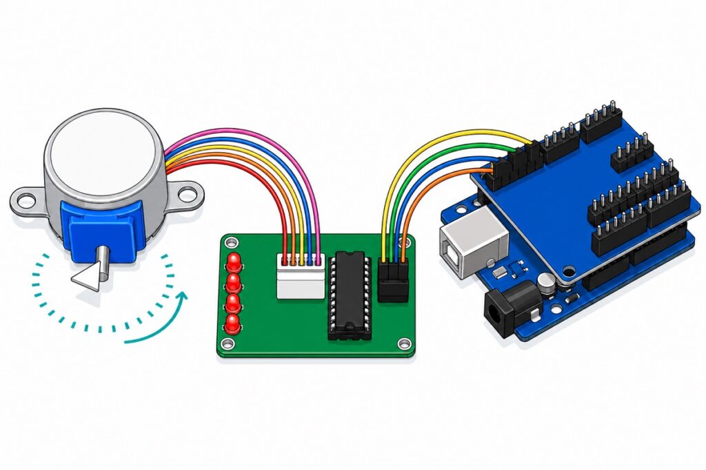
Connect the ULN2003 board’s IN1–IN4 to Arduino pins 8, 9, 10 and 11, feed the board 5V, and instantiate the motor as Stepper(2038, 8, 10, 9, 11) — middle two arguments deliberately swapped. One turn of the output shaft is 2038 countable steps, not the 2048 nearly every sketch assumes, and that ten-step gap is why beginners’ motors slowly drift.
What comes in the 28BYJ-48 kit, and why can’t the driver reach the Uno?
The 28BYJ-48 kit is two items in one bag. The motor’s five wires — blue, pink, yellow, orange and a red common — end in a keyed plug that mates with the green ULN2003 driver board. On that board only four things matter: the IN1–IN4 header (IN5–IN7 are bare holes), the − and + pins under the legend 5–12V, the shunt beside them that switches the motor supply on and off, and the four LEDs.
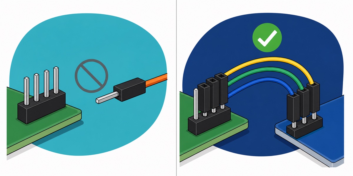
The catch no wiring diagram shows: every connection point on the driver is a male pin, and every header on the Arduino Uno is a female socket. Male-to-female jumpers solve that directly. This guide instead adds a Sensor Shield V5.0, which re-presents every Uno pin as a male G/V/S triple, so plain female-to-female wires bridge male to male.
Do not press the driver into a breadboard. Its two headers run perpendicular to each other, so whichever one crosses the strips has every pin shorted into a single five-hole net — IN1–IN4 tied together, or + straight to −. A snapped length of male header strip in the Uno’s sockets is a cheaper fix that works.
Parts list
 28BYJ-48 Stepper Motor + ULN2003 Motor Driver 5V DC Motor For Arduino Robotic
 Arduino Uno Compatible SMD UNO R3 with Type B Cable - ATMEGA328P with CH340G-Microcontroller Project
 Sensor Shield V5.0 Arduino Uno R3 Shield For Arduino Protoype Application
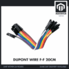 40pcs Dupont Wire 10cm 20cm 30cm for Breadboard DIY Experiment Jumper Wire Breadboard wire - DUPONT WIRE F-F 20CM
Optional: a separate 5V supply
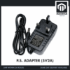 Power Supply Adapter DC Universal AC to DC Converter PSU 5V2A 5V3A 9V2A 12V2A - P.S. ADAPTOR (5V2A)
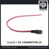 5.5x2.1mm DC Power Male Connector Plug Jack Adapter for Arduino DIY Electronics Projects - 5.5x2.1 DC CONNECTOR (F)
A dedicated 5V rail, for running the motor continuously or adding a second one. Read the power paragraphs first — the shield's SEL jumper must come off before you connect it.
How do you wire and power the ULN2003 board?
The Sensor Shield V5.0 groups digital pins 11, 10, 9 and 8 into one four-wide block, each column a G (ground), V (5V) and S (signal) triple — so that one block carries everything this project needs, and six female-to-female jumper wires finish the job.
| ULN2003 board | Sensor Shield | Uno pin behind it |
|---|---|---|
| IN1 | S pin of the “8” column | D8 |
| IN2 | S pin of the “9” column | D9 |
| IN3 | S pin of the “10” column | D10 |
| IN4 | S pin of the “11” column | D11 |
| + (marked 5–12V) | V pin of any column in that block | 5V |
| − (marked 5–12V) | G pin of any column in that block | GND |
| IN5, IN6, IN7 | Nothing — unpopulated holes | — |
| White 5-pin socket | Motor’s white keyed plug | — |
One shield detail saves an hour: the row silkscreened POWER / RESET 3V3 5V GND VIN is bare plated holes, not pins. Take 5V and GND from the V and G rows of a digital triple instead. And leave the small silver shunt beside the driver’s − and + pins fitted — it switches the motor supply on, so a board that looks wired right yet does nothing is often just that shunt gone missing.
Two safety points before power-up. The PCB is marked 5–12V because that is the motor supply the board passes straight through to the windings — the ULN2003 itself is rated to 50V, so nothing on the board protects the motor. The bundled motor is the 5V model, and 12V will overheat its windings. And never unplug the motor’s connector while the board is powered: breaking an energised coil sends an inductive kick somewhere you did not choose.
USB is enough here. Each phase measures roughly 50 Ω, so at 5V it draws 5 ÷ 50 = 0.1 A, and the sequence holds two phases on at once — about 200 mA moving, against a USB port’s 500 mA and the Uno’s own 40 mA. Take it from USB rather than the Uno’s barrel jack, though: fed 12V, the Uno’s regulator has to burn the surplus as heat, roughly 7 V × 0.24 A = 1.7 W.
A second motor, or one held energised for long stretches, does not fit. The optional row gives it its own rail: the 5V adaptor into the barrel socket pigtail, bare tails into the shield’s blue screw terminal — the barrel’s centre-pin tail to the V/VCC screw, the other to G/GND. The adaptor is centre-positive, so a continuity check settles which tail is which before power-up; swapping the pair feeds the driver backwards. Take the yellow SEL jumper off first. SEL feeds the digital block’s V pins from the Uno’s own 5V, so leaving it fitted shorts the adaptor onto the Uno’s 5V rail and the USB port behind it, which can damage both. The G rail stays common ground regardless, which is what keeps the Uno’s logic levels meaningful to the driver. Never open the mains adaptor or modify its plug end.
Where does 2048 steps per revolution come from?
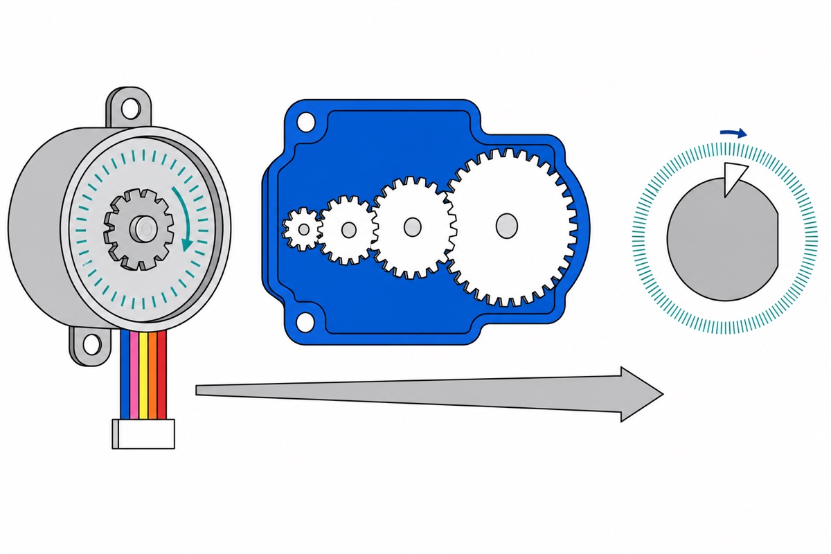
The 28BYJ-48’s rotor, before any gearing, advances 11.25° per full step — 32 full steps per internal revolution. Half-stepping splits each in two, giving the datasheet’s 5.625° stride angle and 64 half-steps per turn. The gearbox then reduces that by a nominal 64:1, so 32 × 64 = 2048 full steps (or 4096 half-steps) at the output shaft.
Except the gearbox is not really 64:1. People who opened one and counted teeth found a four-stage train of exactly (31 × 32 × 26 × 22) ÷ (11 × 10 × 9 × 9) = 63.68395:1. Same arithmetic, honest number: 32 × 63.68395 = 2037.9 steps.
| Quantity | Nominal (64:1) | Measured (63.68395:1) |
|---|---|---|
| Full steps per output revolution | 2048 | 2037.9 |
| Half-steps per output revolution | 4096 | 4075.8 |
| Degrees per full step | 0.1758° | 0.1767° |
That gap is not academic. Command 2048 steps and the shaft rotates 2048 ÷ 2037.9 × 360° = 361.8° — 1.8° of overshoot per revolution, always the same way, so twenty turns later your pointer is 36° out. This is the whole point of a stepper: position falls out of counting, so the count has to be right.
Why is the pin order 8, 10, 9, 11 instead of 8, 9, 10, 11?
The 28BYJ-48’s four phases sit around the stator in connector order, and its published drive sequence energises neighbouring pairs: IN1+IN2, then IN2+IN3, IN3+IN4, IN4+IN1. Each step shares a coil with the one before, and that overlap walks the magnetic field round the ring.
Arduino’s bundled Stepper library drives its four pins in the pattern 1010, 0110, 0101, 1001 — that is, it energises (arg1,arg3), (arg2,arg3), (arg2,arg4), (arg1,arg4). Arguments 1 and 3 pair up first, not 1 and 2.
Line the two lists up and the mapping falls out: arg1 = IN1, arg3 = IN2, arg2 = IN3, arg4 = IN4 — as pin numbers, Stepper(2038, 8, 10, 9, 11). Not a typo everybody copied: a translation between the library’s pairing convention and this motor’s coil order.
Pass the intuitive 8, 9, 10, 11 and every pair lands wrong. Steps 1 and 3 become IN1+IN3 and IN2+IN4 — phases on opposite sides of the stator, pulling against each other into almost no net field at all. Steps 2 and 4 give IN2+IN3 and IN1+IN4: real positions, but 180° apart. The field goes nowhere, one side, nowhere, the other side, so the rotor rocks between two points instead of walking round the ring. Prove it in ten seconds: swap the middle two arguments and listen.
What is the ULN2003 actually doing?
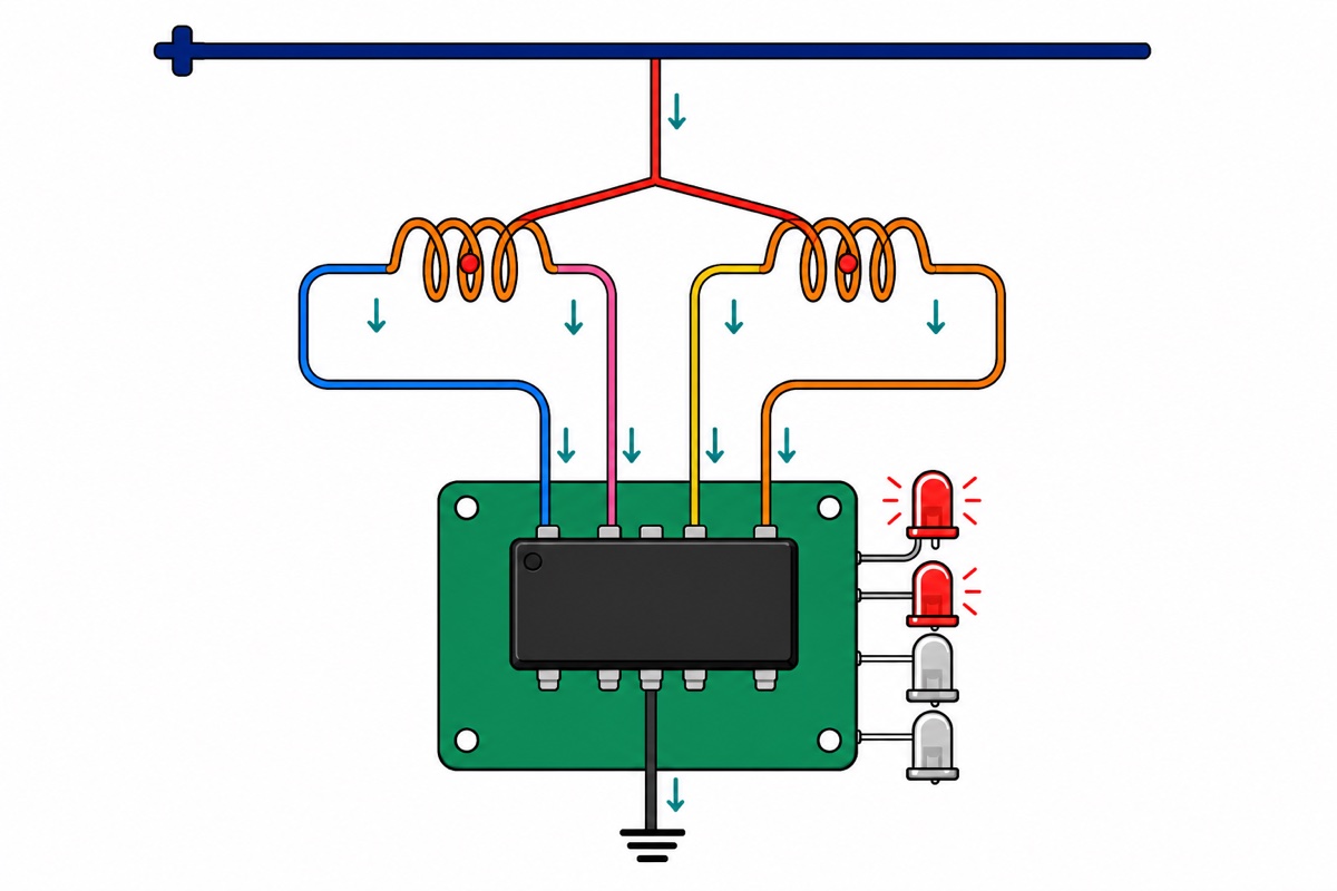
The ULN2003AN packs seven identical Darlington pairs into one 16-pin chip — which is why the board’s silkscreen reaches IN7 while only IN1–IN4 carry pins. The load-bearing word is sink: each channel can only pull its output down to ground, never supply current. That is why the motor’s red wire is a common centre tap held at +5V — current leaves the 5V rail, runs through half a coil, into the chip and out to ground.
Each channel is just a low-side switch, the same job the IRF520 module does with one MOSFET — so current can never reverse in a coil half. That is a unipolar drive: half the copper idle at any instant, torque traded for simplicity.
It also explains the four LEDs: they sit on the outputs, so each lights exactly when its coil is energised — a free logic analyser. Chasing LEDs with a still shaft means a mechanical fault or a half-seated plug; LEDs that never chase mean your pins or your sketch.
A Darlington conducts as long as its input stays HIGH, so the last two coils stay energised when a move ends. That is holding torque, and why the motor gets warm sitting still. Write all four pins LOW when idle, and never leave a stalled motor energised unattended.
What does the complete sketch look like?
The Stepper library ships with the Arduino IDE, so there is nothing to install. This sketch makes four quarter turns with a pause after each, then returns to its origin in one move — working from an absolute step count, so rounding never accumulates.
#include <Stepper.h>

// ULN2003 board -> Arduino Uno (through the Sensor Shield's S pins)
const int IN1 = 8;
const int IN2 = 9;
const int IN3 = 10;
const int IN4 = 11;

// The gearbox is nominally 64:1, but the real gear train measures
// 63.68395:1, so one output revolution is 32 * 63.68395 = 2037.9 steps.
// 2038 is the honest number; 2048 overshoots by about 1.8 deg per turn.
const int STEPS_PER_REV = 2038;

// IMPORTANT: the arguments are IN1, IN3, IN2, IN4 - not 8, 9, 10, 11.
// The library energises the pairs (arg1,arg3), (arg2,arg3), (arg2,arg4),
// (arg1,arg4); swapping the middle two makes those pairs land on coils
// that sit next to each other in the stator.
Stepper motor(STEPS_PER_REV, IN1, IN3, IN2, IN4);

long currentStep = 0;   // where the sketch believes the shaft is

// A Darlington conducts while its input is HIGH, so the coils stay
// energised (and warm) after a move. Let them go when idle.
void releaseCoils() {
  digitalWrite(IN1, LOW);
  digitalWrite(IN2, LOW);
  digitalWrite(IN3, LOW);
  digitalWrite(IN4, LOW);
}

// Move to an ABSOLUTE position counted from where we started.
// Working from an origin instead of adding increments means
// rounding error never accumulates.
void moveTo(long target) {
  motor.step((int)(target - currentStep));
  currentStep = target;
  releaseCoils();

  Serial.print(F("step "));
  Serial.print(currentStep);
  Serial.print(F("  ="));
  Serial.print(currentStep * 360.0 / STEPS_PER_REV, 1);
  Serial.println(F(" deg"));
}

void setup() {
  Serial.begin(9600);
  motor.setSpeed(10);   // rpm; this motor stalls somewhere above ~15 at 5V
  releaseCoils();
  Serial.println(F("28BYJ-48 ready"));
}

void loop() {
  // Four quarter turns, pausing so you can watch each one land
  for (int quarter = 1; quarter <= 4; quarter++) {
    moveTo((long)STEPS_PER_REV * quarter / 4);
    delay(600);
  }

  delay(1000);
  moveTo(0);            // straight back to the origin in one move
  delay(2000);
}
Open the Serial Monitor at 9600 baud: the count should march 509, 1019, 1528, 2038 and back to zero while the shaft makes four clean quarter turns and one full turn home. If it hums but will not move, check the argument order first. Note too that step() blocks until a move ends — nothing else in loop() runs while the shaft is turning.
Nikodem Bartnik’s beginner walkthrough shows the same motor and driver board running on a bench:
Common mistakes we see from real customers
The 28BYJ-48 mistake we see most, by a distance, is the sequential pin order — Stepper(2048, 8, 9, 10, 11) copied from a generic example. It compiles, the LEDs even flicker, and the shaft sits there buzzing.
Next is leaving 2048 in a job that runs for hours and calling the result lost steps. Nothing is lost: a 0.5% generous count shows as steady one-way creep, not the random jumps a real missed step produces.
After that: the breadboard reflex; 12V because the silkscreen says 5–12V; and a dead motor that turns out to be a connector pushed home half way.
FAQ
Should I use 2048 or 2038 steps per revolution?
Use 2038 wherever position matters over time — clocks, indicators, camera sliders. The measured gear ratio is 63.68395:1, not 64:1, so 2048 overshoots by roughly 1.8° per revolution, always the same way. On a demo that spins back and forth, either number looks identical.
Why does my motor get warm when it is not moving?
Because the ULN2003 keeps conducting while your Arduino pins stay HIGH, so the last two coils remain energised after the move ends. That is holding torque — useful when the shaft must stay put, otherwise write all four pins LOW between moves.
Stepper or servo for my project?
A servo when you want a held angle inside roughly 180° with position feedback built in; a stepper when you want unlimited rotation in countable increments and can accept that nothing tells you when a step was missed. Our servo 180 vs 270 vs 360 guide covers the other side.
Is the ULN2003 the right driver, or should I use an L298N or A4988?
The bundled ULN2003 is correct — the 28BYJ-48 is unipolar with a common centre tap, exactly what a Darlington sink array drives. H-bridge boards like the L298N in our line follower robot guide suit bipolar steppers and brushed DC motors; choppers like the A4988 suit NEMA-17 steppers. Different motor classes, not upgrades.
Last updated August 2026. Stuck? Chat with us on WhatsApp.

Pingback: DRV8833 vs L298N: Which Motor Driver to Buy