

Tutorials
Arduino Flame Sensor Fire Alarm with Buzzer (RBT Project)
Jul
A flame sensor module feels no heat at all. It is an infrared photodiode that sees 760–1100nm light; the blue trimmer on the board sets a reference voltage, and an LM393 comparator drops the DO pin from HIGH to LOW the moment the photodiode’s reading crosses that reference. That LOW is what sounds the buzzer — so “adjusting the sensitivity” really means choosing a threshold, and that threshold is something you can measure. Because it detects light in a direct line of sight, this is an RBT classroom demonstrator, not a replacement for a home smoke detector.
How does this flame sensor module know there is a fire?
The FLAME4P flame sensor module is a small teal-blue board with a single black bullet head at one end: a 5mm infrared photodiode that responds to 760nm through 1100nm inside a roughly 60-degree cone. Flames do radiate strongly in that band — but so do plenty of other things, and that one fact explains almost everything this module does.
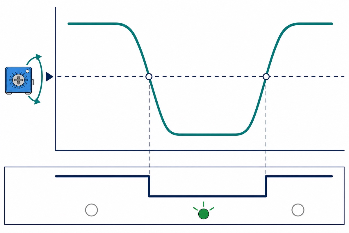
Infrared light landing on the photodiode makes it more conductive, so the divider voltage beside it falls — and that voltage is what comes out raw on the AO pin. The blue trimmer marked 103 (10k) is a second, separate divider, producing a fixed reference voltage that you choose yourself. The eight-legged black chip between them is TI’s LM393 dual comparator, and it has exactly one job: compare those two voltages and announce which is higher.
AO sits high when the air is clear and falls as IR rises — a closer flame gives a lower analogRead(). DO idles HIGH and drops to LOW when flame is detected, at the same instant the DO-LED lights. You can confirm both yourself without taking anyone’s word for it. The LM393 pulls its output LOW when its inverting input is higher than its non-inverting input. Here AO feeds the non-inverting input and the trimmer feeds the inverting one, so a flame that drags AO below the reference level makes the inverting input the higher of the two — and the output is duly pulled LOW. The bench observation and the comparator rule give the same answer.
The LM393’s output is also open-collector: inside there is only a transistor that can pull DO down to GND, and nothing at all that can push it back up. Without a pull-up resistor the pin floats and its HIGH means nothing. The module already carries that resistor on board, so pinMode(pin, INPUT) really is enough; INPUT_PULLUP merely adds a second pull-up in parallel with it.
Learn this board once and you hold the key to many more: the same teal layout with a blue trimmer, an LM393 and a VCC/GND/DO/AO header is our soil moisture module, our sound module, our IR obstacle sensor and our LDR module. The same IR photodiode also reads the floor reflection in a line follower robot — same physics, different job.
Parts list
 Arduino Uno Compatible SMD UNO R3 with Type B Cable - ATMEGA328P with CH340G-Microcontroller Project
 Infrared Flame Sensor Module Fire Detector Sensor Module For Arduino IOT Application
 SFM-20B Active Buzzer DC 3-24V Piezoelectric Long Continous Beep
 MB102 Breadboard 170 400 830 Holes Breadboard Donut Board Arduino Prototype Multi Color - MINI BREADBOARD 170 HOLES (WHITE)
 40pcs Dupont Wire 10cm 20cm 30cm for Breadboard DIY Experiment Jumper Wire Breadboard wire - DUPONT WIRE M-M 30CM
Optional: 9V power supply
| Item | Price | Qty | |
|---|---|---|---|
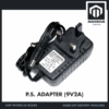 Power Supply Adapter DC Universal AC to DC Converter PSU 5V2A 5V3A 9V2A 12V2A - P.S. ADAPTOR (9V2A)PSA0902 Power Supply Adapter DC Universal AC to DC Converter PSU 5V2A 5V3A 9V2A 12V2A - P.S. ADAPTOR (9V2A)PSA0902 | RM13.95 |
So the alarm can stand on its own without a laptop. 9V lands right in the middle of the Uno's recommended input window; a 5V adapter is not enough for the on-board regulator to do its job.
Why is this a classroom alarm and not home protection?
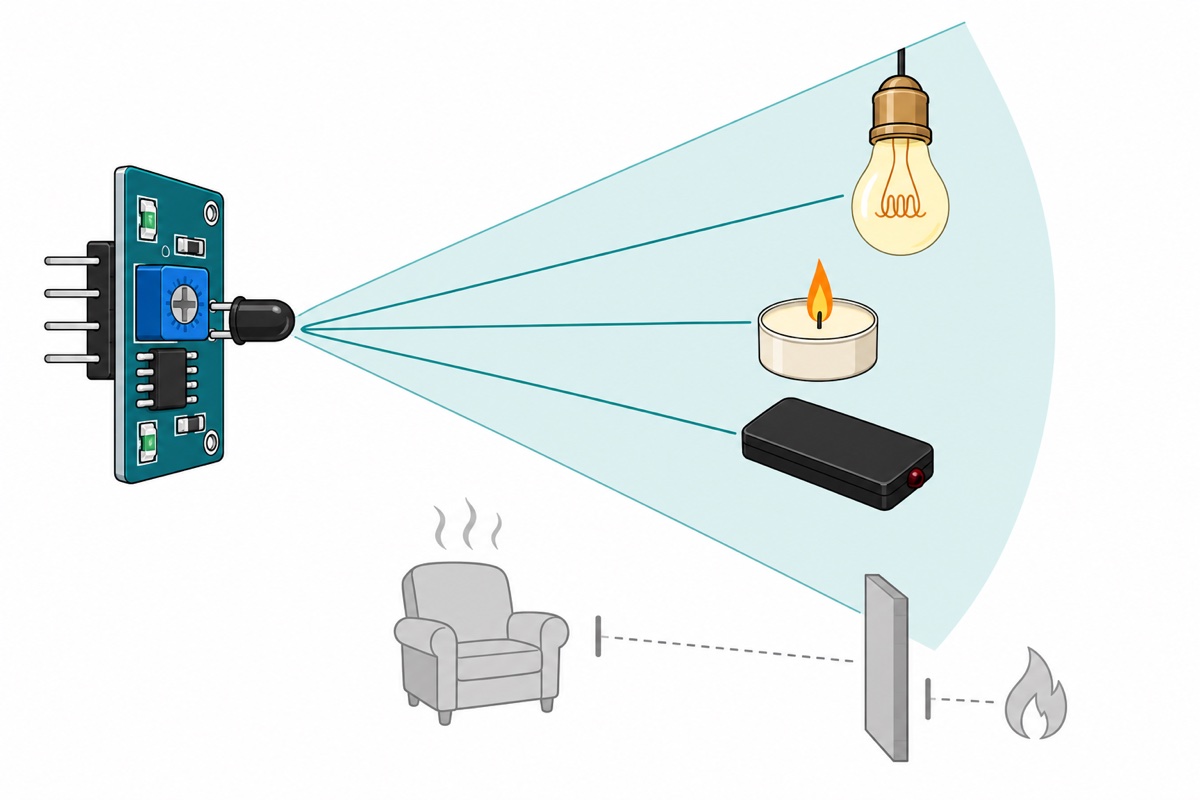
A flame sensor of this type needs a direct line of sight, and that is a physical limit that comes straight out of how it works: it detects light, not fire. So it misses a fire that smoulders slowly without flame, it cannot see smoke at all, and it is blind to a flame behind furniture or in the next room. What protects a house is a certified smoke detector, not this project. If particles and air quality are what you want to detect, our air quality and haze sensor guide is the place to go.
That same limit also explains every false alarm. Sunlight through a window, an incandescent or halogen bulb, the infrared illuminator on a CCTV camera, even the infrared pulses from a TV remote — all of them sit in the same 760–1100nm band. The pattern is easy: what fools this sensor is anything that glows, not merely anything hot.
Testing with a real flame follows ordinary lab discipline. A small candle or a lighter at arm’s length, with a teacher or another adult supervising, on a clear table with no flammable material nearby; don’t use a large flame, and never leave it unattended. Everything else in this build is entirely low-voltage DC — the only mains-related item is that optional wall adapter, a sealed double-insulated unit you simply plug into a socket, never open and never modify.
How do you wire the flame sensor, the buzzer and the Uno?
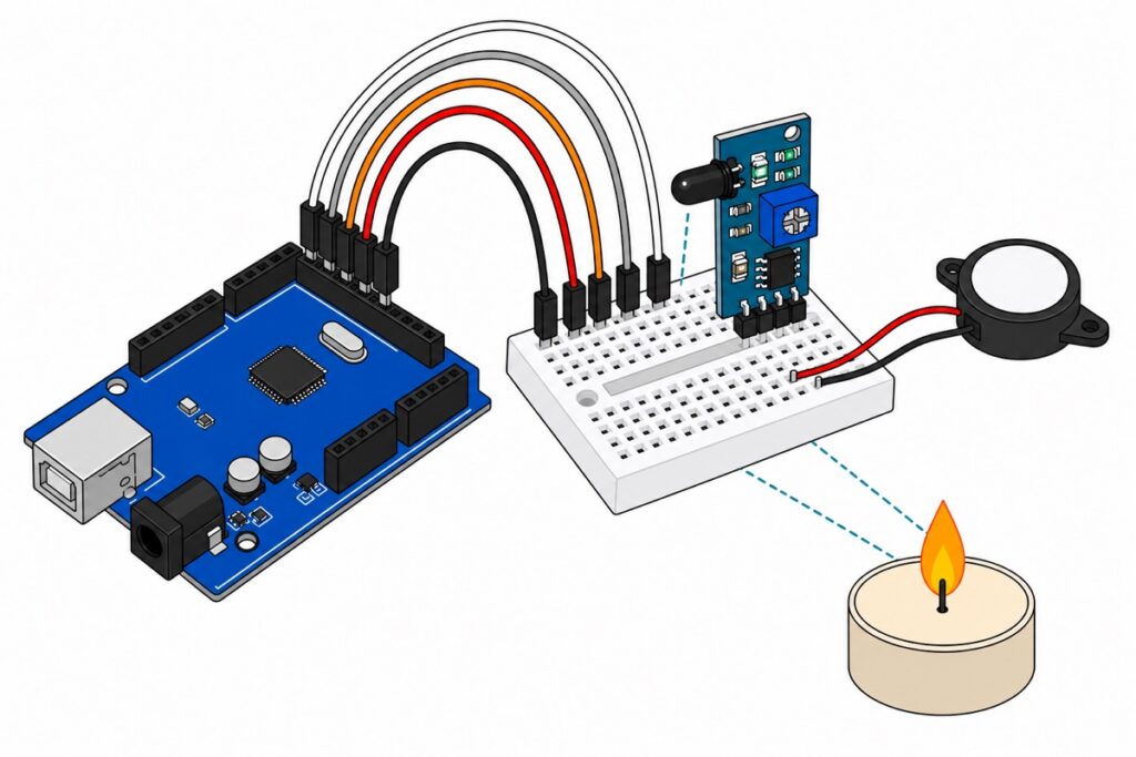
The FLAME4P comes out of the bag with one interface only: a row of four male 2.54mm header pins marked VCC, GND, DO, AO. The Arduino Uno‘s user-facing headers are all female sockets. Male pins do fit female sockets — the problem is a different one: the module’s four pins sit side by side, while the four signals it needs (5V, GND, D2 and A0) are scattered across three different Uno headers. So the module cannot be plugged straight into the board, and every signal needs its own wire. The SFM-20B buzzer has a different problem again: its two wires end in bare tinned copper with no connector at all — push them into a female header and they splay out and work loose halfway through the demo.
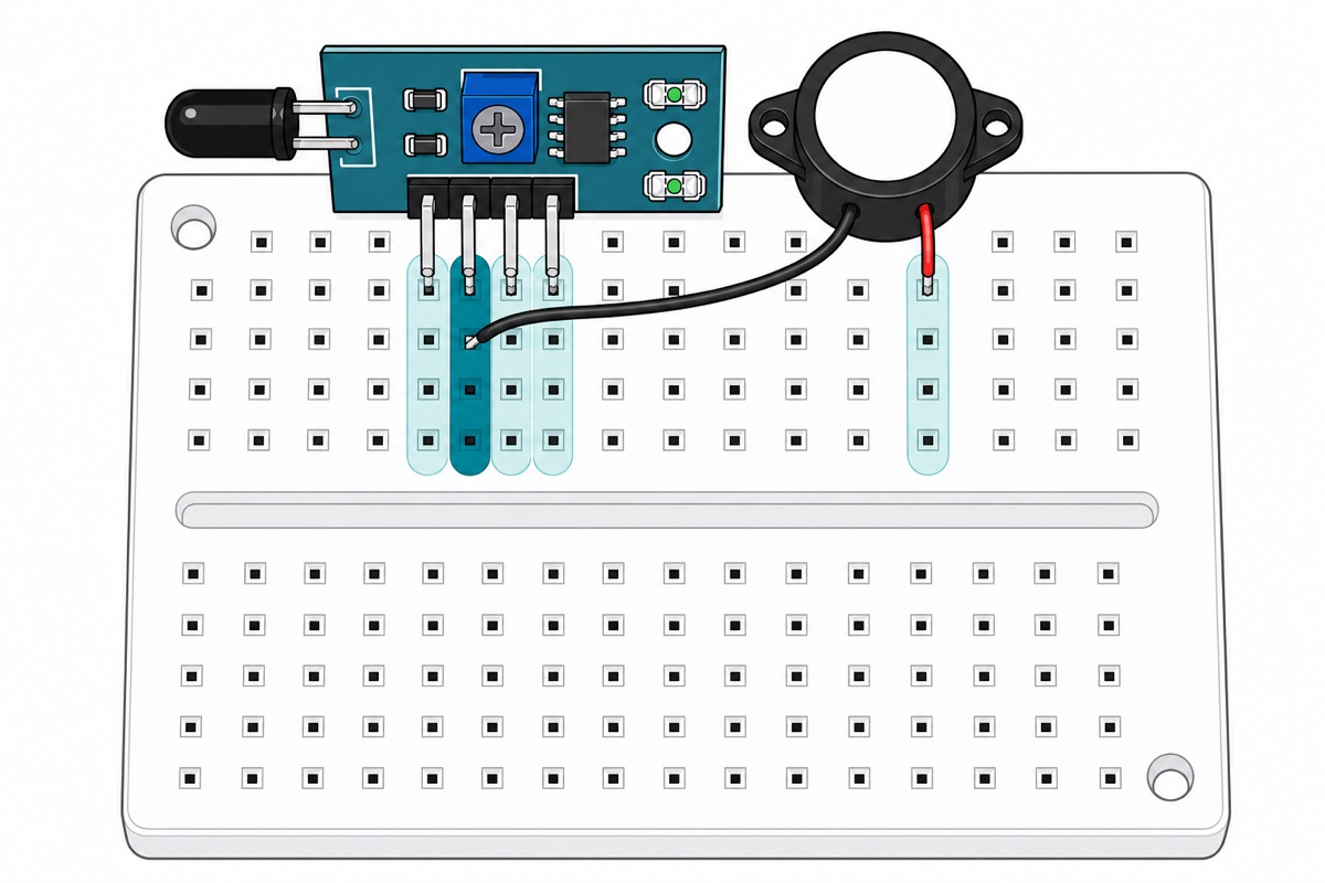
A 170-point mini breadboard solves both at once, because the spring clips inside it are made to grip male pins and bare wire ends. Note this: the 170-point size has no + and − power rails. Its own count proves it — two blocks × 17 columns × 5 holes = exactly 170, so every hole already belongs to a terminal strip and there is nothing left over for rails. Wire this build using columns only. The column numbers aren’t printed on this board either, so “Column 1” in the table below means the first of four adjacent columns you pick yourself.
That leads to the most useful thing about a breadboard: the five holes in one column are one and the same electrical point. That is why the buzzer’s black wire can go into the same column as the module’s GND pin — both are already joined inside the board, so only one Uno GND pin is needed. The module’s pins come out of the end of the board rather than its face, so the board stands upright when plugged in — and the black bullet head, which juts out of the opposite end, ends up looking at the ceiling instead of across the table. Bend its two legs gently, or tilt the module, so the head faces the area you want to cover; confirm with the DO-LED at the real distance.
| From | Breadboard column | To Uno | Wire |
|---|---|---|---|
| FLAME4P — VCC | Column 1 | 5V | M-M jumper |
| FLAME4P — GND | Column 2 (shared) | GND | M-M jumper |
| FLAME4P — DO | Column 3 | D2 | M-M jumper |
| FLAME4P — AO | Column 4 | A0 | M-M jumper |
| Buzzer — RED wire (+) | A separate column | D8 | M-M jumper |
| Buzzer — BLACK wire (−) | Column 2, with the module’s GND | — | No extra wire |
Five male-to-male jumpers and no more, because that last row is solved by the breadboard rather than by a wire. This buzzer is polarised: red to the driven pin, black to GND; reverse it and it simply stays silent.
This buzzer needs no transistor, and here is the arithmetic. The SFM-20B is rated at 12V DC with a maximum current draw of 12mA at that rating (operating range 3–24V, fixed 3300±500Hz tone), so driven at 5V it draws less. On the Uno side, the ATmega328P datasheet puts the Absolute Maximum DC current per I/O pin at 40.0mA, and guarantees its output levels at 20mA — at VCC 5V sourcing 20mA, a pin is still guaranteed at least 4.2V. Under 12mA sits comfortably below both figures.
The honest flip side: this buzzer’s headline loudness figure is quoted at that rated 12V, so at 5V it is quieter — enough for a bench or classroom demo, not a siren. Want the full scream? Run the buzzer at 12V and let a small transistor do the switching. Not a relay for this job — that is a mechanical switch, and a beep pattern several times a second would eat through its contact cycle life.
How do you calibrate that blue trimmer properly?
The FLAME4P’s 10k trimmer sets a threshold, so calibrating it is not “turn it until it works” — it is a measurement. That is why the sketch below prints analogRead(A0) to the Serial Monitor: that number gives you two boundary markers.
- Open the Serial Monitor at 9600 baud, clear table, no flame. Note the AO reading that settles — that is your “clear” number.
- Hold a flame at the distance you actually want to cover, say 20 centimetres. Note the new AO reading; it will be lower.
- Turn the trimmer slowly until DO changes state between those two numbers. The DO-LED switches at the same instant, so the trip point is visible without looking at the screen. There is no need to memorise which way to turn: with a clear table, turn a little and watch which direction lights the DO-LED — that is the more sensitive direction.
That is also why winding the trimmer hard to either end never works. One end puts the reference above your clear reading, so DO stays LOW and the alarm sounds without stopping; the other end puts it below your flame reading, so DO never moves at all. A useful threshold always sits between those two measurements.
Want to see that DO-LED actually snap over as the screw turns? This module demo films the same hardware:
What does the Arduino code for this fire alarm look like?
The SFM-20B is an active buzzer — its oscillator is built in, so digitalWrite(HIGH) sounds it and digitalWrite(LOW) silences it. tone() will not change its pitch and it cannot play a melody; the intermittent beeping comes from your code, not from the buzzer.
One more design decision worth explaining: this sketch demands five consecutive readings confirming flame before it sounds. Samples are taken every 20 milliseconds and the alarm only arms on the fifth, so a flame must hold for 80 to 100 milliseconds unbroken — 80ms is the gap between the first and fifth samples, and the rest depends on sampling phase. A camera flash lasts only a few milliseconds and a remote control sends short pulses with gaps between them — neither can fill that window, while a real flame fills it easily. A tenth of a second, meanwhile, delays nothing that matters.
// Fire alarm: flame sensor module (FLAME4P) + active buzzer SFM-20B.
// This module's DO is active-LOW: it idles HIGH and drops to LOW on flame.
// AO moves the other way - highest with no flame, and it falls as IR
// rises. Serial prints both so you can calibrate that blue trimmer from
// the real numbers your own unit gives.

const int PIN_DO   = 2;    // module's digital output (already pulled up on the board)
const int PIN_AO   = A0;   // photodiode divider voltage, raw
const int PIN_BUZZ = 8;    // buzzer's red wire

// Sample every 20 ms, and 5 consecutive hits before calling it flame:
// the flame must hold for 80-100 ms unbroken. A camera flash and the short
// pulses from a TV remote cannot fill that window; a real flame can.
const unsigned long SAMPLE_MS    = 20;
const int           CONFIRM_HITS = 5;

// Intermittent beeping is easier to hear than one continuous scream, and
// this active buzzer only understands HIGH or LOW - so the pattern has to
// come from the code.
const unsigned long BEEP_ON_MS  = 400;
const unsigned long BEEP_OFF_MS = 200;

// Print calibration readings 4 times a second so the Serial Monitor stays readable.
const unsigned long PRINT_MS = 250;

unsigned long lastSample = 0;
unsigned long lastPrint  = 0;
unsigned long beepMark   = 0;

int  hits     = 0;       // how many consecutive samples have confirmed flame
bool alarming = false;
bool beepHigh = false;

void setup() {
  Serial.begin(9600);

  // INPUT, not INPUT_PULLUP. The LM393 output is open-collector - it can
  // only pull LOW - and the module already carries its own pull-up
  // resistor, so the Uno's internal pull-up has no job here.
  pinMode(PIN_DO, INPUT);

  pinMode(PIN_BUZZ, OUTPUT);
  digitalWrite(PIN_BUZZ, LOW);

  Serial.println(F("Flame sensor ready. AO high = no flame. DO LOW = flame detected."));
}

void loop() {
  unsigned long now = millis();

  if (now - lastSample >= SAMPLE_MS) {
    lastSample = now;

    bool flameNow = (digitalRead(PIN_DO) == LOW);

    if (flameNow) {
      if (hits < CONFIRM_HITS) hits++;
    } else {
      hits = 0;
    }

    bool wantAlarm = (hits >= CONFIRM_HITS);

    if (wantAlarm && !alarming) {
      alarming = true;
      beepHigh = true;
      beepMark = now;
      digitalWrite(PIN_BUZZ, HIGH);
      Serial.println(F("FLAME DETECTED - alarm on"));
    } else if (!wantAlarm && alarming) {
      alarming = false;
      beepHigh = false;
      digitalWrite(PIN_BUZZ, LOW);
      Serial.println(F("Clear - alarm off"));
    }
  }

  // Intermittent beep pattern, without delay(), so the sensor keeps being read.
  if (alarming) {
    unsigned long span = beepHigh ? BEEP_ON_MS : BEEP_OFF_MS;
    if (now - beepMark >= span) {
      beepMark = now;
      beepHigh = !beepHigh;
      digitalWrite(PIN_BUZZ, beepHigh ? HIGH : LOW);
    }
  }

  // Calibration line: AO first, then the DO state the trimmer decides.
  if (now - lastPrint >= PRINT_MS) {
    lastPrint = now;
    Serial.print(F("AO="));
    Serial.print(analogRead(PIN_AO));
    Serial.print(F("  DO="));
    Serial.println(digitalRead(PIN_DO) == LOW ? F("LOW (flame)") : F("HIGH (clear)"));
  }
}
Notice there is no delay() inside loop(). The beep pattern is driven by millis(), so the sensor keeps being read every 20ms even while the buzzer is sounding — otherwise the alarm goes deaf to the world for the length of every single beep.
Notice the asymmetry as well: five samples to arm the alarm, but a single clear sample is enough to shut it off. A buzzer that stutters means your threshold sits too close to your flame reading. Want it to keep sounding until it is switched off? Hold alarming at true once it goes on, and let the Uno’s reset button be the only thing that clears it.
Common mistakes we see from real customers
The most frequent one with this flame sensor module is reading DO the wrong way round: code that treats HIGH as flame gives an alarm that sounds all the time and only goes quiet when a flame is shown to it. Number two: expecting a tune out of an active buzzer, trying tone(), then deciding the buzzer must be faulty.
Then there is the trimmer wound hard to one stop — permanently on at one end, stone deaf at the other — when its place is between two measured AO readings. It usually pairs with another: the test bench set up beside a window in direct sunlight, followed by the conclusion that the sensor is broken when it is working exactly as it should.
Two more are hardware. The buzzer’s tinned wires pushed straight into the Uno’s female headers, then splaying out and dropping free halfway through the demo — that is why a breadboard is in the parts list. And for power: pick a 9V adapter, not a 5V one. The Uno’s barrel jack feeds the on-board regulator, and a regulator can only step voltage down — which is why Arduino recommends 7–12V on that jack, and 9V sits neatly in the middle.
Arduino flame sensor FAQ
Why does my buzzer sound non-stop even with no flame?
Almost always DO read the wrong way round. This module is active-LOW, so your test has to be digitalRead(pin) == LOW. If the code is already right, a DO-LED that stays lit means the trimmer’s reference sits above your clear AO reading — turn it back until that LED goes out.
Can this sensor replace a smoke detector at home?
No, and it isn’t a question of component quality. It detects light in a direct line of sight, so a fire that smoulders without flame, smoke itself, and a flame behind a wall are all missed. Use it as an RBT demonstrator or a school electronics project, and let a certified smoke detector protect the house.
Why does the alarm go off when a light is switched on or the curtains open?
The photodiode responds to 760–1100nm, and sunlight, incandescent bulbs, halogen lamps and the infrared illuminators on CCTV cameras all radiate strongly in that band. Move the sensor out of direct sunlight, then recalibrate it where it will actually be used.
Can the SFM-20B buzzer play a melody with tone()?
No. It is an active buzzer with a built-in oscillator at 3300±500Hz, so there is only one pitch. digitalWrite() HIGH sounds it and LOW silences it; beep patterns are made by timing that pin in code.
Do I need a transistor to drive this buzzer from an Arduino pin?
No. The SFM-20B is rated at 12V with a maximum current draw of 12mA at that rating, so at 5V it draws less — comfortably under the 40.0mA Absolute Maximum per I/O pin set by the ATmega328P datasheet. A transistor is only needed if you take the buzzer up to 12V.
Last updated August 2026. Stuck? Chat with us on WhatsApp.
