

Tutorials
How to Build a Line Follower Robot with Arduino Uno
May
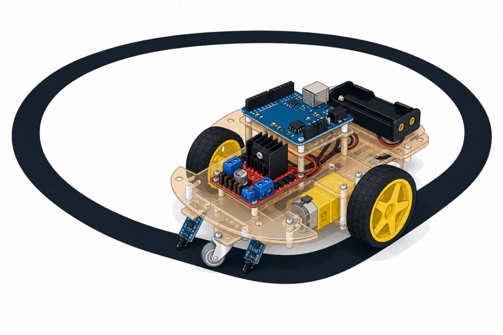
How to build a line follower robot: put together four parts — a 2WD chassis with two TT motors, two IR sensors facing down to read the black line, an Arduino Uno that makes the decisions, and an L298N that spins the motors. Both sensors seeing white means drive straight; whichever sensor sees black, that is the way the robot turns.
How does a line follower robot work?
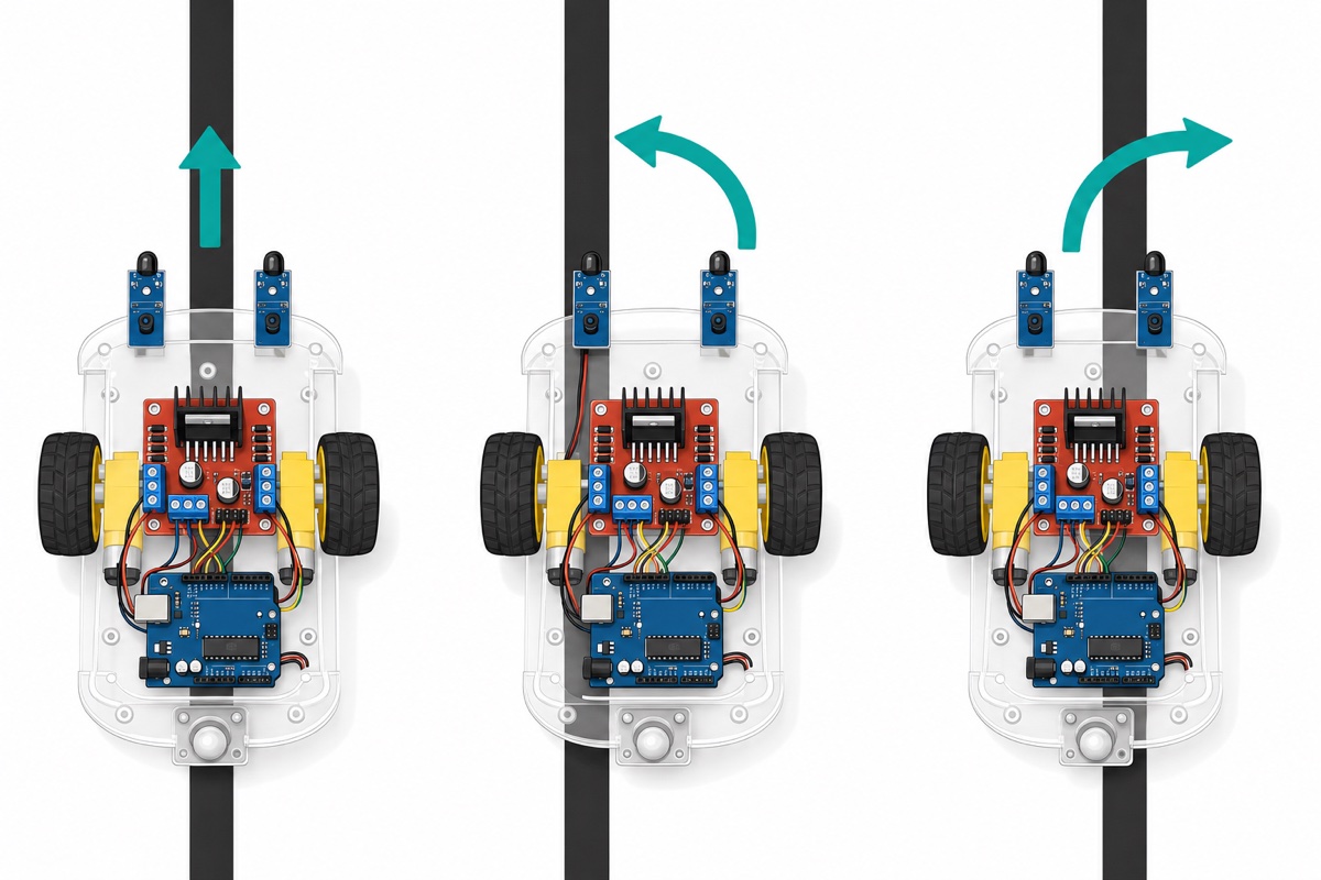
A line follower robot follows a black line on a white surface using very simple logic. Two IR sensors sit at the front of the robot, one on the left and one on the right of the line. As long as both see white, the robot drives straight — the line is sitting right in the middle.
When the robot drifts off course, one of the sensors “steps on” the black line. The Arduino stops the motor on that same side, so the robot steers back onto the line. This method is called bang-bang control — no complicated maths, which makes it perfect for RBT and FYP projects.
| Left sensor | Right sensor | Robot action |
|---|---|---|
| White | White | Drive straight |
| Black | White | Turn left |
| White | Black | Turn right |
| Black | Black | Stop (finish line or junction) |
What components do you need?
The 2WD chassis kit already includes two TT motors, wheels, a caster and screws — you only add the brain (Arduino Uno), the motor driver (L298N), two IR sensors and a power supply. Everything is in this list.
Parts list
 2WD 4WD Smart Car Chassis Single Layer Acrylic Arduino Smart Car Chassis Kit With Motor - 2WD CAR KIT
 Arduino Uno Compatible SMD UNO R3 with Type B Cable - ATMEGA328P with CH340G-Microcontroller Project
 L298N Motor Driver Module Arduino Compatible Dual H Bridge Dual DC Motor Control Arduino Robotic Car
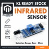 IR sensor Infrared Range Finder Adjustable Distance Sensor Obstacle Avoidance Arduino Robotic
 3.7V 18650 Battery Rechargeable Li-Ion Battery 1200mAh 2200mAh 3200mAh Flat Top - 18650 Li-Ion Battery (2200mAh)
 18650 Battery Holder 1/2/3/4 Slot 3.7V Battery Cell Housing Battery Case Battery Casing - 18650 BATTERY HOLDER (2)
One important note: the TT motor tabs in the 2WD chassis kit need wires soldered on before they can connect to the L298N. It is a two-minute job — if you have never soldered before, follow our guide on how to solder header pins; the technique is the same.
What does the L298N do in a line follower robot?
The L298N is a dual H-bridge motor driver — it drives two DC motors at the same time and can reverse the direction of each one. Arduino pins cannot supply motor current, so the L298N plays middleman: the Arduino gives the logic commands, the L298N delivers the power from the battery.
Each motor’s direction is controlled by its pair of IN pins according to this table (IN1/IN2 for motor A, IN3/IN4 for motor B):
| IN1 | IN2 | Motor A |
|---|---|---|
| LOW | LOW | Stop |
| HIGH | LOW | Spin forward |
| LOW | HIGH | Spin backward |
| HIGH | HIGH | Stop |
Speed is controlled through the ENA and ENB pins. The module ships with jumpers fitted on both — jumper on means the motor only ever runs at full speed. Remove the ENA and ENB jumpers and connect those pins to Arduino PWM pins; only then can analogWrite() control the speed. Speed control is compulsory on a line follower — at full speed the robot almost always overshoots the line.
About voltage: the L298N uses bipolar transistors, so there is a voltage drop of around 1.8–2.5V between the battery and the motors according to the ST L298 datasheet. With two 18650 batteries (7.4V nominal), the motors actually receive roughly 5–5.6V — which happens to match TT motors rated 3–6V. That is why the 2×18650 + L298N pairing is the classic school-robot recipe.
Bonus: keep the 5V-EN jumper (onboard regulator) in place, because our supply is below 12V — the 5V terminal on the L298N will output 5V that can power the Arduino Uno directly through its 5V pin. No separate battery needed for the Arduino. Only if you use a supply above 12V does this jumper need to come off. Note: while uploading code over the USB cable, disconnect the 5V wire from the L298N to the Arduino first (or unplug the battery) — never feed USB and the L298N into the 5V pin at the same time.
How do the IR sensors read the black line?
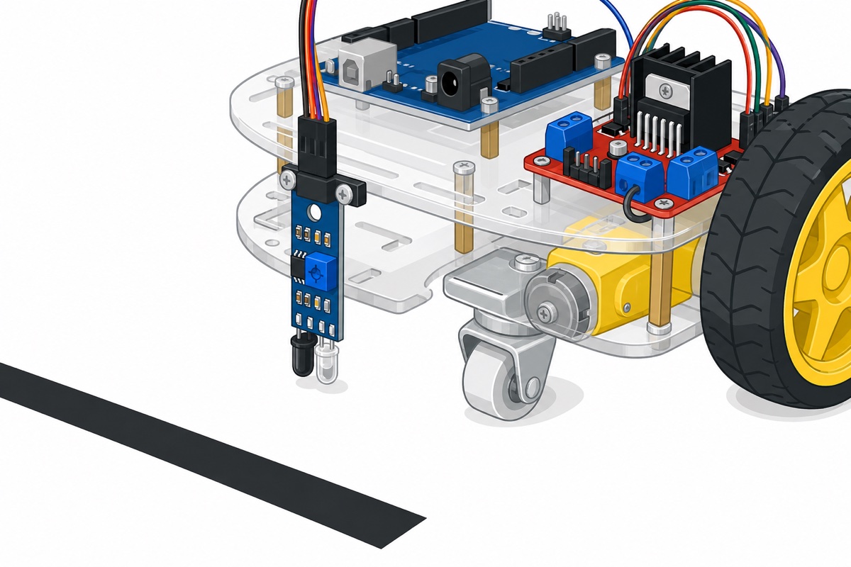
These FC-51 IR sensors are actually reflection sensors: the black LED emits infrared light, and the clear LED beside it waits for the reflection. For a line follower, we mount the sensors facing down, about 1–2cm from the floor. A white surface reflects IR well; black tape absorbs it.
| Surface under the sensor | IR reflection | Output (OUT) |
|---|---|---|
| White | Reflection present | LOW (active LOW when reflection is detected) |
| Black tape | Absorbed, no reflection | HIGH |
Notice the logic is the reverse of what most people expect: LOW means white, HIGH means black. This is the number one reason robots “do their own thing” — the code below already uses the correct logic.
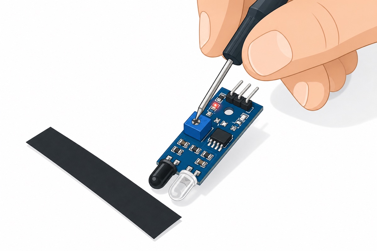
The square blue trimmer on top of the sensor adjusts sensitivity, and this is the most critical step of the whole project. The ritual goes like this: hold the sensor at its real mounting height above a white surface, and turn the trimmer slowly until the indicator LED lights up steadily. Then push the robot over the black tape — the LED must go off. Repeat the adjustment until both states are consistent, and do it for both sensors.
How do you wire everything together?
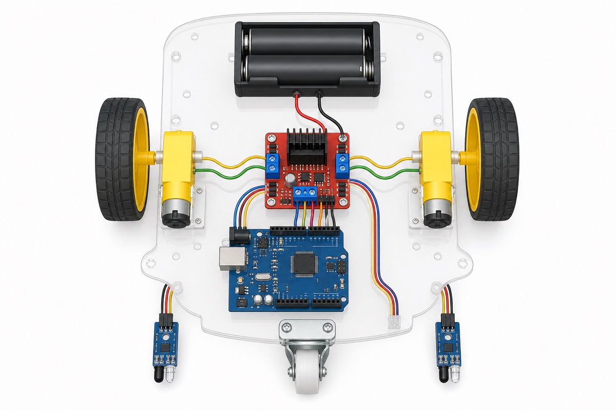
The wiring on this robot looks like a lot but it is well organised — the L298N is the hub in the middle. The left motor goes into the OUT1/OUT2 terminals, the right motor into OUT3/OUT4, the battery into the 12V and GND terminals, and all the control signals come from the Arduino.
| From | Pin / wire | Connect to |
|---|---|---|
| 18650 holder (2 slots) | Red (+) | L298N 12V terminal |
| Black (−) | L298N GND terminal + Arduino GND (must be shared) | |
| L298N | 5V terminal | Arduino 5V pin (5V-EN jumper stays on) |
| L298N control pins | ENA (remove jumper) | Pin 5 (PWM) |
| IN1 | Pin 7 | |
| IN2 | Pin 8 | |
| IN3 | Pin 9 | |
| IN4 | Pin 10 | |
| ENB (remove jumper) | Pin 6 (PWM) | |
| Left IR sensor | VCC | Arduino 5V |
| GND | Arduino GND | |
| OUT | Pin 2 | |
| Right IR sensor | VCC | Arduino 5V |
| GND | Arduino GND | |
| OUT | Pin 3 |
The 4xAA holder from the chassis kit is fine for quick tests, but the 2-slot 18650 holder with two Li-ion cells gives far more stable voltage under load — no more robot going “sleepy” halfway around the track.
What is the full Arduino code for a two-sensor robot?
This Arduino code implements the bang-bang logic. Notice that LAJU (Malay for speed — the identifiers in this sketch are in Malay) is set to PWM 150, not 255 — at full speed, the robot flies past the line before the sensors can react. Start at 150 and raise it gradually if your track has plenty of straights.
// 2-sensor line follower robot - Arduino Uno + L298N
// Remember: these IR sensors are active LOW - LOW = WHITE (reflection detected), HIGH = BLACK

const int SENSOR_KIRI  = 2;    // left sensor OUT
const int SENSOR_KANAN = 3;    // right sensor OUT

const int ENA = 5;             // left motor speed PWM (jumper removed)
const int IN1 = 7;
const int IN2 = 8;
const int IN3 = 9;
const int IN4 = 10;
const int ENB = 6;             // right motor speed PWM (jumper removed)

const int LAJU = 150;          // PWM 0-255; full speed easily overshoots the line

void setup() {
  pinMode(SENSOR_KIRI, INPUT);
  pinMode(SENSOR_KANAN, INPUT);
  pinMode(ENA, OUTPUT); pinMode(IN1, OUTPUT); pinMode(IN2, OUTPUT);
  pinMode(ENB, OUTPUT); pinMode(IN3, OUTPUT); pinMode(IN4, OUTPUT);
  Serial.begin(9600);          // open the Serial Monitor to check sensor readings
}

void jalanTerus() {
  digitalWrite(IN1, HIGH); digitalWrite(IN2, LOW);   // left motor forward
  digitalWrite(IN3, HIGH); digitalWrite(IN4, LOW);   // right motor forward
  analogWrite(ENA, LAJU);
  analogWrite(ENB, LAJU);
}

void belokKiri() {
  analogWrite(ENA, 0);         // left motor stops
  digitalWrite(IN3, HIGH); digitalWrite(IN4, LOW);
  analogWrite(ENB, LAJU);      // right motor pushes - robot pivots left
}

void belokKanan() {
  digitalWrite(IN1, HIGH); digitalWrite(IN2, LOW);
  analogWrite(ENA, LAJU);      // left motor pushes - robot pivots right
  analogWrite(ENB, 0);         // right motor stops
}

void berhenti() {
  analogWrite(ENA, 0);
  analogWrite(ENB, 0);
}

void loop() {
  // HIGH = sensor sees BLACK (no reflection)
  bool kiriHitam  = (digitalRead(SENSOR_KIRI)  == HIGH);
  bool kananHitam = (digitalRead(SENSOR_KANAN) == HIGH);

  if (!kiriHitam && !kananHitam) {
    jalanTerus();              // both white: line is centred
  }
  else if (kiriHitam && !kananHitam) {
    belokKiri();               // left sensor on the line: turn left
  }
  else if (!kiriHitam && kananHitam) {
    belokKanan();              // right sensor on the line: turn right
  }
  else {
    berhenti();                // both black: finish line / junction
  }
}
Before the robot goes anywhere near the track, lift it up and test: hold a piece of white paper under the right sensor only — the left sensor, up in the air, reads black, so the right wheel should spin. If the response is reversed, the left and right motor wires are most likely swapped at the L298N terminals.
How do you build the track and tune the sensors?
The classic school track is also the cheapest: black electrical insulation tape (18–19mm wide) stuck onto white mahjong paper or a whiteboard. Build an oval circuit first — avoid sharp corners until the robot is stable. The gap between the two sensors should be slightly wider than the tape, around 3–4cm, so both sit over white while the robot is centred on the line.
Then run the trimmer ritual on the actual track, not on a table — room lighting and floor type both affect IR reflection. Open the Serial Monitor, print both sensor readings, and confirm white = LOW, black = HIGH at the sensor’s real height before you let the robot go.
Want to see the same build assembled and running on a track? This video shows the Arduino, L298N and IR sensor combination from start to finish:
Common mistakes we see from real customers
Sensors mounted too high
This is the most frequent mistake. At 4–5cm up, the sensor starts “seeing” reflections from a wide area — including the floor beside the tape — and the readings turn random. Keep it at 1–2cm from the floor, and make sure both sensors sit at the same height.
ENA/ENB jumpers not removed
With the jumpers still fitted, analogWrite() has no effect at all — the motors run at full speed and the robot overshoots every corner. If your robot is ridiculously fast and ignores the LAJU value in the code, check these jumpers first.
Sensor logic reversed in the code
Many people assume HIGH = something detected. For this type of reflection sensor, LOW is what means “seeing white”. If the robot drives when it should stop, or turns the wrong way the moment you power on, print the sensor readings to the Serial Monitor and match them against the table above.
GND not shared between the Arduino and L298N
PWM and IN signals only mean something when the Arduino and L298N share the same reference. Forget to connect Arduino GND to L298N GND and the motors will behave strangely or not move at all — even when every other wire is correct.
FAQ
Why does my robot leave the line at corners?
Three suspects: PWM too high (bring it down to around 130–150), track corners too sharp for two-sensor logic, or trimmer sensitivity not yet tuned on the actual track. Work through them one at a time, starting with speed.
Can I use the 4xAA holder that comes with the chassis kit?
Yes, for quick tests, but alkaline battery voltage sags quickly under load — and after the L298N “eats” around 2V, the motors only get around 3–4V. Two 18650 batteries give far more consistent torque and speed.
Why use an Arduino Uno instead of an ESP32?
For two-sensor logic with no WiFi, the Uno is simpler: fully 5V (the same voltage as the sensors and the L298N), tougher pins, and nearly every school code example is written for the Uno. Read the full comparison in ESP32 vs ESP8266 vs Arduino Uno.
Why does the robot stop when both sensors see black?
That is intentional in the code — both HIGH usually means a finish line across the track or a junction. If you want the robot to drive through junctions, change berhenti() to jalanTerus() in the last block and watch how it behaves.
What is this project good for besides competitions?
It is a great foundation for an RBT folio and FYP because it covers sensors, a motor driver and control logic in a single build. If you want a second school project that uses the same skills, try the automatic clothesline with rain sensor.
Last updated August 2026. Stuck? Chat with us on WhatsApp.
