

Tutorials
Stepper vs Servo vs DC Motor: Which One for Your Arduino?
Aug
Buy a servo when the part must reach a known angle and hold it — a gate arm, a robot joint, a pan-tilt head. Buy a stepper when it must turn to a counted position, keep turning past one revolution, or hold against a load — a dial, a slider, a feeder. Buy a plain DC gear motor when only speed and direction matter — wheels, fans, pumps.
Price is not the tiebreaker — the three families answer different questions, and the quickest way to feel the difference is to push gently against each output shaft.
What actually separates a stepper, a servo and a DC motor?
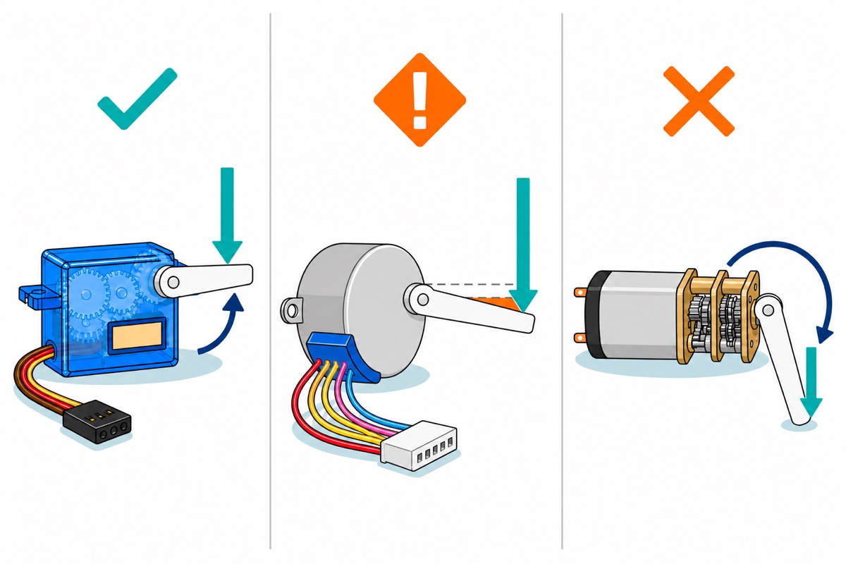
An RC servo such as the SG90 is four parts in one case: a small DC motor, a gear train, a potentiometer geared to the output shaft, and a chip that compares. You send a pulse every 20 ms whose width — roughly 1.0 ms to 2.0 ms — stands for an angle. The chip compares that width against the potentiometer’s voltage and drives the motor until the two agree. Push the horn off its angle and the potentiometer voltage moves with it, the comparison unbalances, and the servo drives itself straight back. That loop is also the limit: the potentiometer only rotates so far, so a 180° servo cannot spin continuously, and nothing outside the case can read where the shaft ended up. One caution before you try that push: nudge the arm, do not fight it. An SG90’s gear train is nylon, and forcing it against a powered motor strips a tooth — which is exactly what the MG996R’s metal gears are sold to survive. With no horn on the boss, a folded strip of masking tape gives you a lever.
The 28BYJ-48 stepper has no sensor at all. Its rotor is a permanent magnet surrounded by coils; energise them in sequence and the rotor snaps to each new magnetic alignment, one step per switch. Torque comes from a powered coil holding the rotor in a magnetic detent rather than from a correction loop — which is why a stepper has genuine holding torque while powered, and why push-testing one feels like pushing a notched dial. Overload it and the rotor slips a detent: the step count in your sketch keeps rising, nothing reports the slip, and the error stays in the machine until you re-home.
The GA12-N20 gear motor gives up position entirely. Voltage across two terminals spins the shaft, reversed terminals spin it the other way, and chopping the voltage with PWM slows it down. Push its shaft and it simply turns — nothing in it has an opinion about angle. In exchange it is the cheapest continuous rotation you can buy, and its gearbox trades a fast weak motor for a slow strong one.
| Family | You command | Rotation | Holding torque | Knows its position? | Buy it for |
|---|---|---|---|---|---|
| 28BYJ-48 stepper + ULN2003 | A count of steps | Unlimited, either way | Yes, while powered | No — open loop, slips silently | Dials, sliders, feeders, anything that must turn more than one revolution to a set place |
| SG90 micro servo | An absolute angle | About 180°, no further | Yes, actively corrected | Internally yes, externally no | Light arms, flaps, latches, pan-tilt heads — roughly 1.3 kg·cm at 4.8 V |
| MG996R metal-gear servo | An absolute angle | About 180°, no further | Yes, and far more of it | Internally yes, externally no | The same jobs under real load — about 11 kg·cm at 6 V, metal gears |
| GA12-N20 DC gear motor | Speed and direction | Unlimited, either way | None | No, and it cannot | Wheels, fans, pumps, conveyors — anything where “how far” is not the question |
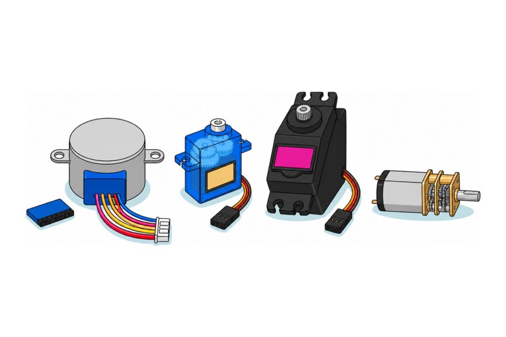
The four motors compared — these are alternatives, buy the ONE that matches your job
 28BYJ-48 Stepper Motor + ULN2003 Motor Driver 5V DC Motor For Arduino Robotic
 SG90 MG90 Tower Pro Micro Servo Motor 9g 180 360 Servo Motor for Arduino Robotic - SG90- 180°
 SG90 MG90 Tower Pro Micro Servo Motor 9g 180 360 Servo Motor for Arduino Robotic - MG996R- 180°
 GA12-N20 DC Geared Motor 3V 5V 6V 9V 12V Gear Motor For Arduino Smart Car Application
What a bench trial of them needs
 Arduino Uno Compatible SMD UNO R3 with Type B Cable - ATMEGA328P with CH340G-Microcontroller Project
 L298N Motor Driver Module Arduino Compatible Dual H Bridge Dual DC Motor Control Arduino Robotic Car
 40pcs Dupont Wire 10cm 20cm 30cm for Breadboard DIY Experiment Jumper Wire Breadboard wire - DUPONT WIRE M-M 20CM
 40pcs Dupont Wire 10cm 20cm 30cm for Breadboard DIY Experiment Jumper Wire Breadboard wire - DUPONT WIRE M-F 20CM
 Data Cable Type-A Type-C MicroUSB Type-B 0.5m 1m 30cm 0.3m 100cm Data Transfer Upload Code - TYPE-A TO TYPE-B (1.0M)
One Uno drives all four motors. The stepper brings its own ULN2003 board, so the only driver to add is an L298N for the DC motor — screw terminals and pre-fitted headers, nothing to solder. Take both jumper genders: male-to-female for the driver boards' male pins, male-to-male for the servos' female sockets. The Type-B cable is the one an Uno uses.
Picking the wrong arc is the next mistake after picking the wrong family, and 180° vs 270° vs 360° servos settles that one. First, what is physically inside a servo case:
How many motors can one Arduino Uno actually drive?
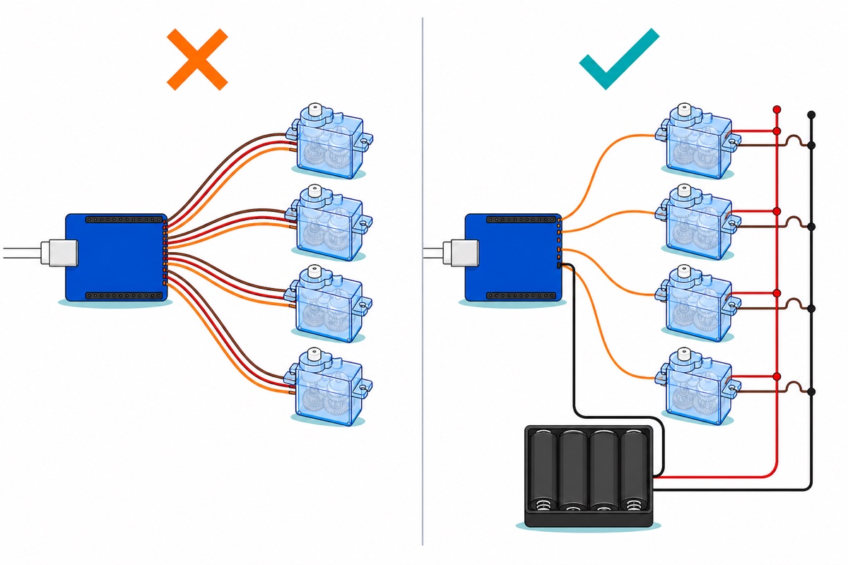
The Arduino Uno has two budgets — pins and amps — and the smaller one decides. Pins are the easy count: 14 digital plus 6 analog usable as digital is 20, minus D0 and D1 for the USB serial, leaves 18. A ULN2003 stepper board takes four, so four steppers fit with two pins spare. A servo takes one, but the Arduino Servo library caps an Uno at 12 and, from the first attach() call, disables analogWrite() on pins 9 and 10 — whether or not a servo sits on those two. A DC motor takes two direction pins plus a PWM pin through a driver — never a pin directly, because an Uno pin is rated 20 mA and even a small N20 pulls hundreds of milliamps at stall.
Amps are the budget that actually stops you, and the stepper’s figure is worth deriving. Each 28BYJ-48 coil measures about 50 Ω, so at 5 V one coil pulls roughly 100 mA and the bundled Stepper library keeps two coils energised at every step — call it about 200 mA per motor, drawn whether it turns or merely holds. The MG996R currents in the table are TowerPro’s own; the SG90 sheet is written around torque and speed, so its row uses typical measured draw. USB gives the whole board 500 mA, set by the port and by the resettable fuse behind the Uno’s socket. The barrel jack is no bigger a 5 V budget: behind it is a small linear regulator burning the difference as heat — about 0.4 W for every 100 mA at 9 V in — and at 5 V in it has no headroom left and browns the board out instead.
So the fix is never a bigger board, it is a second supply — motors on their own 5–6 V rail, signal wires to the Uno, grounds joined so the pulses share a reference. The ULN2003 board and the L298N both carry power terminals for exactly this. Keep the stepper’s rail at 5 V: the ULN2003 chip will switch far more, but the 28BYJ-48 is a 5 V winding and the extra goes to heat, not torque. Past a handful of servos, move pulse generation off the Uno entirely with a PCA9685 16-channel driver, which has its own servo power input.
| Family | Pins each | Current each | Pin ceiling on an Uno | Realistic ceiling on USB power |
|---|---|---|---|---|
| Stepper on a ULN2003 board | 4 digital | ~200 mA, moving or holding | 4 | 1 |
| SG90 micro servo | 1 (library max 12) | 100–250 mA moving, ~360 mA stalled | 12 | 1 moving at a time |
| MG996R metal-gear servo | 1 (library max 12) | 500–900 mA at 6 V, 2.5 A stalled | 12 | 0 — needs its own supply |
| DC motor through an L298N | 2–3 | Hundreds of mA, more at stall | 6, at 2 motors per L298N | 0 — motor supply is separate by design |
How do you actually command each family?
An Arduino Uno can speak all three languages in one sketch, and this one does: an absolute angle to the servo, a count of steps to the stepper, a direction and a duty cycle to the DC motor. Three details cost people evenings. First, the bundled Stepper library was written for bipolar motors: it reads your four pins as A+, A-, B+, B- and fires them in the pairs 1st+3rd, 2nd+3rd, 2nd+4th, 1st+4th. A unipolar 28BYJ-48 needs adjacent overlapping pairs instead — IN1+IN2, IN2+IN3, IN3+IN4, IN4+IN1 — so wire IN1–IN4 to D4–D7 but list them 4, 6, 5, 7, which maps one pattern onto the other. In plain numeric order the library energises coils that pull the rotor opposite ways, and it buzzes in place.
Second, the DC motor’s PWM pin is D3, not D9 or D10, because attaching a servo hands Timer1 — the timer behind those two pins — to the Servo library. Third, pull the jumper cap off the L298N’s ENA header before you expect analogWrite() to mean anything: that cap ties ENA permanently to the board’s own 5 V, so the motor runs flat out at any duty cycle — speed control that fails silently, with no error to read.
Notice what the stepper line cannot tell you. stepper.step(512) means “switch the coils 512 times”, not “arrive at a quarter turn” — and the 28BYJ-48’s gearbox is nearer 63.7:1 than a round 64:1, so one output turn is about 2038 steps, not 2048; command the round number and you land roughly two degrees past where you meant to be, even when nothing slips. Steppers are counted, not measured; add an endstop and re-home where that matters. Note too that stepper.step() blocks until the last step is issued, so nothing else in the loop runs meanwhile — one Uno commands all three families by taking turns, not simultaneously.
// Three families, three command styles - Arduino UNO.
//
// Servo   : you send an ABSOLUTE ANGLE. The servo finds it and holds it.
// Stepper : you send a COUNT OF STEPS. Nothing reports back whether it arrived.
// DC      : you send a SPEED and a DIRECTION. Position is not part of the language.
//
// POWER: run all three motors from an external 5V supply, NOT from the Uno's 5V pin,
// and join that supply's ground to the Uno's GND so the control signals share a reference.

#include <Servo.h>
#include <Stepper.h>

// --- Stepper: 28BYJ-48 on a ULN2003 board -----------------------------------
// 32 full steps per internal revolution x the gearbox. The real gearbox is
// 63.68:1, not a round 64:1, so one output turn is about 2038 steps - the
// conventional 2048 kept here overshoots by roughly two degrees.
const int STEPS_PER_REV = 2048;

// Watch the order: the Stepper library expects IN1, IN3, IN2, IN4.
// Wire IN1..IN4 to D4..D7 and list them 4, 6, 5, 7 or the motor only buzzes.
Stepper stepper(STEPS_PER_REV, 4, 6, 5, 7);

// --- Servo ------------------------------------------------------------------
const int PIN_SERVO = 9;      // attach() hands Timer1 to Servo, so analogWrite()
Servo arm;                    // on pins 9 and 10 stops working sketch-wide.

// --- DC motor through an L298N ---------------------------------------------
const int PIN_DC_EN = 3;      // ENA - PWM, on Timer2, untouched by Servo.h.
                              // Remove the L298N's ENA jumper cap or this pin does nothing.
const int PIN_DC_A  = 2;      // IN1
const int PIN_DC_B  = 8;      // IN2

void setup() {
  Serial.begin(9600);

  stepper.setSpeed(10);       // rev/min at the output shaft

  arm.attach(PIN_SERVO);
  arm.write(90);              // park in the middle of the arc

  pinMode(PIN_DC_EN, OUTPUT);
  pinMode(PIN_DC_A,  OUTPUT);
  pinMode(PIN_DC_B,  OUTPUT);

  Serial.println(F("Servo = angle, stepper = steps, DC = speed"));
}

void loop() {
  // 1. SERVO - absolute position inside a fixed arc.
  Serial.println(F("servo -> 0 deg"));
  arm.write(0);
  delay(700);
  Serial.println(F("servo -> 180 deg"));
  arm.write(180);
  delay(700);
  arm.write(90);
  delay(700);

  // 2. STEPPER - counted steps, no limit on total rotation, no feedback.
  Serial.println(F("stepper -> +512 steps (a quarter turn, if nothing slipped)"));
  stepper.step(512);
  delay(400);
  Serial.println(F("stepper -> -512 steps back"));
  stepper.step(-512);
  delay(400);

  // 3. DC MOTOR - direction pins pick which way, PWM picks how hard.
  Serial.println(F("dc -> forward, about 60% duty"));
  digitalWrite(PIN_DC_A, HIGH);
  digitalWrite(PIN_DC_B, LOW);
  analogWrite(PIN_DC_EN, 160);        // 160/255 of the supply, not "60% speed"
  delay(1500);

  Serial.println(F("dc -> coast"));
  analogWrite(PIN_DC_EN, 0);
  delay(1200);
}
Watching a 28BYJ-48 actually step, and hearing what a wrong pin order sounds like, saves a lot of guessing:
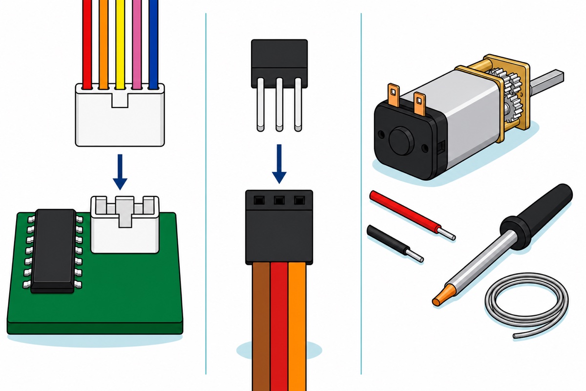
The 28BYJ-48’s five wires end in a keyed plug that drops onto its ULN2003 board, so that pair needs nothing extra. The servos end in female sockets and take male-to-male leads; the ULN2003 and L298N present male pins and want male-to-female. The N20 is the one to plan for: it arrives bare, two copper solder tabs and no leads, so set aside a few minutes with an iron — our iron and flux guide covers the technique. A DRV8833 dual driver suits a 3–6 V motor better than an L298N, whose bipolar output stage drops 1.8 V to 3.2 V at 1 A before the motor sees anything — on a 5 V rail, a third to two-thirds of the voltage lost to heat before the shaft moves. The DRV8833’s own header strip ships loose, so it costs the same iron time the N20 does.
Should a stepper’s coils be wired in series or in parallel?
A stepper motor’s series-versus-parallel coil wiring is a real choice, but only on a motor that brings both halves of each phase winding out separately — an eight-lead bipolar motor, usually NEMA-frame. Wire the two halves in series and the phase’s resistance doubles while its inductance rises about fourfold, because inductance follows the square of the turns: the driver supplies half the current for the same magnetic pull, but current builds far more slowly from the same drive voltage, so torque fades sooner as the step rate climbs. Wire them in parallel and the inductance falls to roughly a quarter of the series figure while the driver must push about twice the current — the same torque standing still, a far flatter torque curve at speed. So: series for low-speed pull from a modest driver, parallel for speed.
The 28BYJ-48 sits outside that choice. It is a five-wire unipolar motor — one common red lead tied to the supply, four coil ends switched to ground by the ULN2003 — with no second half-winding to rewire either way. If your project genuinely needs the series-or-parallel decision it needs an eight-lead bipolar stepper and a current-chopping driver; if it does not, use the ULN2003 board the 28BYJ-48 ships with — our step-by-step 28BYJ-48 guide takes that wiring from plug to first rotation.
Common mistakes we see from real customers
Buying a 180° servo to drive a wheel. A positional servo has a mechanical stop and a potentiometer that ends; it cannot rotate continuously whatever pulse you send. Wheels want a DC gear motor or a purpose-built continuous-rotation servo.
Feeding motors from the Uno’s 5 V pin. The commonest cause of a board that resets mid-move, or a servo that jitters: start-up and stall current collapses the 5 V rail below the microcontroller’s brownout threshold.
Expecting a stepper to know where it is. After a jam or a step rate the motor could not follow, the sketch’s count and the real shaft position no longer agree, and nothing flags it. Design in a home switch, or accept the drift.
Ordering a bare motor with no way to connect it. The N20 arrives with two solder tabs and no wires at all — plan the iron time, or pick a motor that ships with leads.
FAQ
Arduino stepper motor vs servo — which one should I use?
Use a servo for “go to this angle and hold it” within about 180°, a stepper for “turn a counted amount” or anything past one revolution. A servo corrects itself because it measures its own shaft; a stepper measures nothing, so it turns forever but loses steps in silence.
How many stepper motors can an Arduino control?
Four ULN2003 boards fit an Uno’s pins — four each out of 18 usable — but only one runs comfortably from USB power. Each 28BYJ-48 pulls roughly 200 mA continuously, so four need an external 5 V supply of about an amp, ground tied to the Uno’s.
Should stepper motor coils be wired in series or in parallel?
Series gives more torque at low speed for less driver current; parallel needs about twice the current but holds torque better at higher step rates. The choice only exists on eight-lead bipolar steppers. The 28BYJ-48 is five-wire unipolar and cannot be wired either way.
What is a stepper motor used for?
Anything that must reach a repeatable position while turning further than a servo’s arc: printer and scanner mechanisms, 3D printer axes, camera sliders, rotating displays, valves, dispensers and dial indicators. Holding torque while stopped is often the real reason it was chosen.
What are the advantages of a stepper motor over a DC motor?
Positioning without any sensor, since each pulse is one known increment; real holding torque when stopped, which a DC motor has none of; and precise low-speed running without a gearbox. The costs are a four-wire driver, continuous current even at standstill, and no warning when it slips.
Last updated August 2026. Stuck? Chat with us on WhatsApp.
