

Tutorials
WEMOS D1 R32 (ESP32 in Uno Form): Arduino IDE Setup, Pinout and Uno Shields
Nov
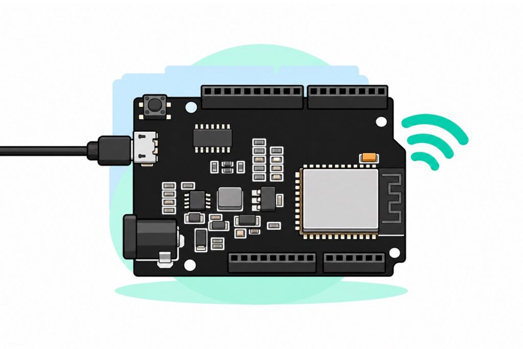
Quick answer: The WEMOS D1 R32 is an ESP32 (ESP32-WROOM-32 module) on an Arduino Uno-shaped board. Its pins work at 3.3V, so it is not a drop-in Uno.
- Use a micro-USB data cable. No port? Install the CH340 driver.
- In Arduino IDE install “esp32 by Espressif Systems”, then pick Tools > Board > esp32 > WEMOS D1 R32.
- The number printed beside a top-row socket (IO26, IO18) is the GPIO number you type in code. The built-in blue LED is IO2.
- With WiFi on, analog readings work only on the Uno A2 to A5 sockets (IO35, IO34, IO36 and IO39).
- Never put 5V into a pin. Check a shield against the table below first.
Parts you need
Pick the WEMOS D1 R32 when a school or FYP lab already owns Uno cases and shields: its sockets line up with them. For a breadboard build, a 30-pin ESP32 DevKit fits better (which ESP32 to buy).
Parts list: WEMOS D1 R32 first upload
 WEMOS R32 Development Board ESP32 WiFi + Bluetooth Module Dual Core MCU Arduino Compatible
 Data Cable Type-A Type-C MicroUSB Type-B 0.5m 1m 30cm 0.3m 100cm Data Transfer Upload Code - MicroUSB CABLE (1.0M)
Parts list
 MB102 Breadboard 170 400 830 Holes Breadboard Donut Board Arduino Prototype Multi Color - BREADBOARD (400 HOLES)
 40pcs Dupont Wire 10cm 20cm 30cm for Breadboard DIY Experiment Jumper Wire Breadboard wire - DUPONT WIRE M-M 20CM
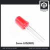 Round Head LED 3mm / 5mm / 8mm - Red/Yellow/Blue/Green/White - 5mm LED (RED)
 400 pcs 1/4W Resistor Pack Resistor Kit 20 Common Value with 20 each
For the external LED test. Any 220 to 330 ohm resistor from the pack works.
The board ships without a cable, so a micro-USB data cable is in the list. Its headers are female sockets, so male-to-male jumpers run straight to a breadboard.
Step 1: Plug in and find the CH340 port
The WEMOS D1 R32 reaches your computer through a CH340 USB-to-serial chip. Plug the cable in: the red power LED lights and a new port appears under Tools > Port (a COM number on Windows, a /dev/cu. name on a Mac).
No new port? A charge-only cable has no data wires, so the board lights up but the computer never sees it. Otherwise the CH340 driver is missing: on Windows, install it from WCH’s driver page and replug (recent macOS has one built in). Our ESP32 not detected guide covers both.
Step 2: Choose WEMOS D1 R32 in Arduino IDE and upload a blink
- In Boards Manager, install esp32 by Espressif Systems (Espressif’s install guide). Not “Arduino ESP32 Boards”, which only covers the Nano ESP32.
- Pick Tools > Board > esp32 > WEMOS D1 R32, then your port.
- Paste this sketch and click Upload.
// Board: Tools > Board > esp32 > WEMOS D1 R32
// Blinks the built-in blue LED and an optional LED on the socket printed IO26,
// then prints what three Uno-style names mean on this board.

const int EXT_LED = 26;  // socket printed IO26 (the Uno D2 position)

void setup() {
  Serial.begin(115200);
  pinMode(LED_BUILTIN, OUTPUT);  // LED_BUILTIN is GPIO2 on this board
  pinMode(EXT_LED, OUTPUT);
}

void loop() {
  digitalWrite(LED_BUILTIN, HIGH);
  digitalWrite(EXT_LED, HIGH);
  delay(500);
  digitalWrite(LED_BUILTIN, LOW);
  digitalWrite(EXT_LED, LOW);
  delay(500);
  Serial.printf("D2 = GPIO%d, A0 = GPIO%d, LED_BUILTIN = GPIO%d\n", D2, A0, LED_BUILTIN);
}
No button press is needed: the CH340 drives the ESP32’s reset (EN) and IO0 pins through two transistors, so the IDE starts download mode by itself. The blue LED should blink, and Serial Monitor at 115200 baud should print D2 = GPIO26, A0 = GPIO2, LED_BUILTIN = GPIO2.
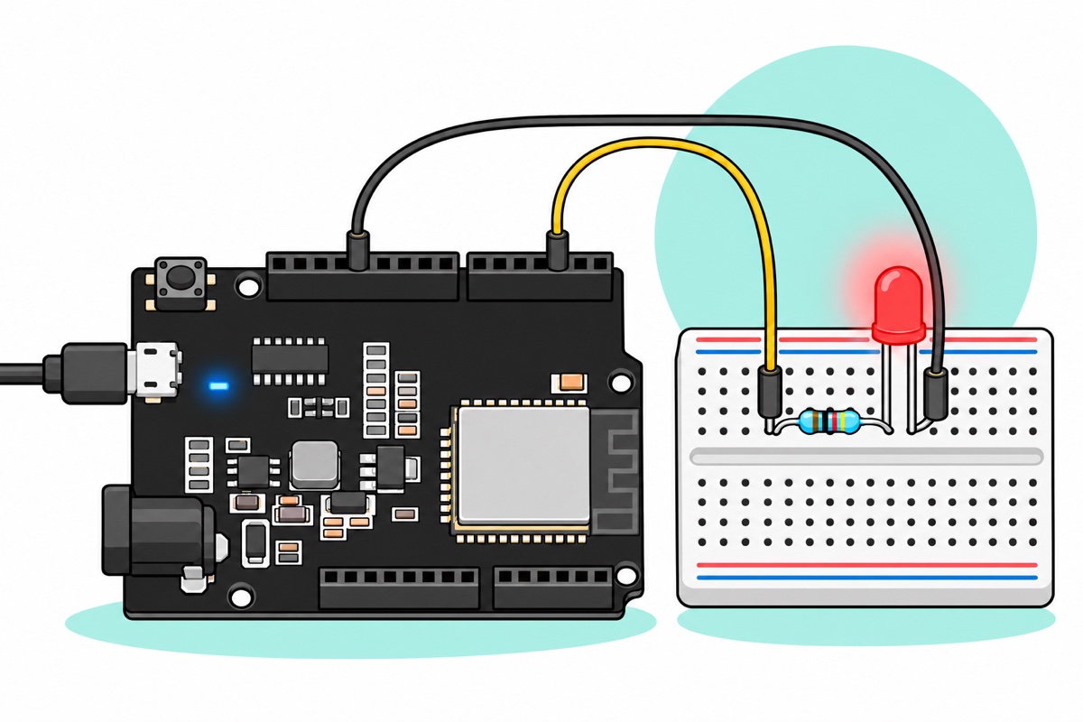
Optional LED test: a red LED drops about 2V, so 220 ohm passes (3.3 − 2) ÷ 220, about 6mA, well under the 20mA default pin drive strength in the Espressif ESP32 datasheet.
| From | To |
|---|---|
| Socket printed IO26 (top row, third from the antenna end) | One leg of a 220 or 330 ohm resistor from the resistor pack (reading the colour bands) |
| Other leg of the resistor, in its own breadboard row | Long leg of the red LED (anode) |
| Short leg of the LED (cathode) | Socket printed GND on the top row |
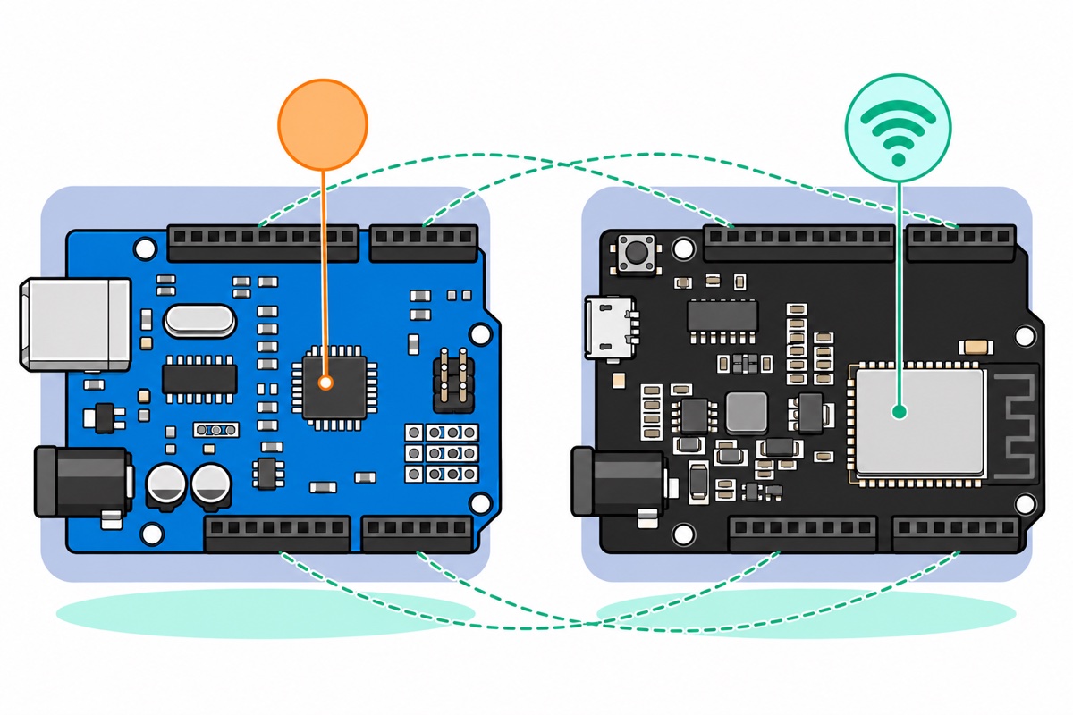
WEMOS D1 R32 pinout: Uno position to ESP32 GPIO
Every socket on the WEMOS D1 R32 has three names: its Uno position (D2), the label printed beside it (IO26) and the name you type in code. The IO number is the ESP32’s own GPIO number and works under any board entry: digitalWrite(26, HIGH).
Uno names depend on the board entry, because each entry loads a file (pins_arduino.h) saying which GPIO a name stands for. Espressif’s file for WEMOS D1 R32 defines D0 to D13, A0 to A5 and LED_BUILTIN. Under “ESP32 Dev Module” the sketch above stops with errors such as 'D2' was not declared in this scope, and A0 means GPIO36, this board’s A4 position. DevKit tutorials use plain GPIO numbers, so their code runs here too, unless it uses IO15, IO32 or IO33, which sit on bare pads here.
| Uno position | ESP32 GPIO | Good to know |
|---|---|---|
| Top row, 10 sockets, counted from the reset button end | ||
| SCL | IO22 | I2C clock |
| SDA | IO21 | I2C data |
| AREF | RST | The reset line here, not a voltage reference |
| GND | GND | |
| D13 | IO18 | SPI SCK |
| D12 | IO19 | SPI MISO |
| D11 | IO23 | SPI MOSI |
| D10 | IO5 | SPI SS. Read at reset |
| D9 | IO13 | |
| D8 | IO12 | Read at reset: must be low |
| Top row, 8 sockets, continuing towards the antenna | ||
| D7 | IO14 | |
| D6 | IO27 | |
| D5 | IO16 | |
| D4 | IO17 | |
| D3 | IO25 | |
| D2 | IO26 | Used for the LED test |
| D1 | TX (IO1) | USB serial, shared with the CH340 |
| D0 | RX (IO3) | USB serial, shared with the CH340 |
| Bottom row, 8 power sockets, counted from the DC jack end | ||
| Unused on an Uno | IO0 | Read at reset: low means download mode |
| IOREF | 5V | See the shield table |
| RESET | RST | |
| 3.3V | 3V3 | |
| 5V | 5V | |
| GND | GND | |
| GND | GND | |
| VIN | VIN | |
| Bottom row, 6 analog sockets, continuing towards the antenna | ||
| A0 | IO2 | Built-in blue LED. ADC2. Read at reset |
| A1 | IO4 | ADC2 |
| A2 | IO35 | ADC1, input only. Some boards print IO36 here |
| A3 | IO34 | ADC1, input only |
| A4 | IO36 | ADC1, input only. A label reading IO38 here is wrong: the module has no GPIO38 |
| A5 | IO39 | ADC1, input only |
| Pads with no header | ||
| None | IO15, IO33, IO32 | Spare pins. IO32 and IO33 are ADC1 and work as inputs or outputs once you solder a header |
| None | SD2, SD3, CMD, CLK, SD0, SD1 | Wired to the module’s flash memory. Never use them |
On the analog row, count positions: some boards, and a widely copied pinout picture, label A2 as IO36 and A4 as IO38, which RIOT’s board documentation marks as wrong.
Will my Uno shield work on the D1 R32?
A shield that fits the WEMOS D1 R32’s sockets can still fail, because the chip behind them is not an Uno’s.
The pins are 3.3V. The ESP32 datasheet caps a pin’s input at the supply plus 0.3V, so 3.6V. 5V from a shield is 1.4V over that cap and can damage the chip for good.
Some pins are read at reset. Before your sketch starts, the ESP32 samples a few “strapping” pins to decide how to start. IO12 (the D8 position) picks the flash memory’s supply: low gives 3.3V, high gives 1.8V. This module’s flash needs 3.3V (Espressif’s note on GPIO12), and an internal pull-down of about 45k keeps IO12 low. A shield’s 10k pull-up to 3.3V on D8 beats it: 3.3 × 45 ÷ 55 is 2.7V, above the 2.48V (0.75 × 3.3V) the chip counts as high. The flash then gets 1.8V, the program cannot be read, and the board looks dead until the shield comes off. IO2 (the A0 position) matters for uploads: download mode needs IO0 and IO2 both low at reset, so a shield pulling A0 high blocks every upload.
The analog pins are split. The WiFi driver uses the ADC2 converter itself (ESP-IDF ADC notes), so the ADC2 pins, A0 and A1 here, cannot take readings while WiFi is on. A2 to A5 are on ADC1 and keep reading, but GPIO34 to 39 have no output driver and no pull-ups (ESP-IDF GPIO page): inputs only.
| Check on the shield | What happens on the D1 R32 | What to do |
|---|---|---|
| A signal that swings to 5V (a 5V sensor’s output, a pull-up to 5V) | Over the 3.6V pin limit | Divide a one-way signal into the board: 10k in series, then 20k (two 10k in series) from the pin to GND. 5V × 20 ÷ 30 is 3.3V. A two-way line such as I2C cannot go through a divider: run that module from 3V3 if its datasheet allows, so its pull-ups sit at 3.3V |
| A chip on the shield that runs on 5V and takes signals from the board | The board’s HIGH is 3.3V at most. Many 5V CMOS chips need 70% of their supply, 3.5V, before they count a signal as high, so 3.3V is not guaranteed to count as high | Look up the input-high voltage (VIH) in the chip’s datasheet. It must be below 2.64V, the lowest HIGH the ESP32 datasheet guarantees (0.8 × 3.3V) |
| Anything wired to AREF | That socket is the ESP32’s reset line here. Pulled low, it holds the chip in reset, and 5V on it is over the 3.6V limit | Leave AREF unconnected |
| A pull-up or an always-high signal on D8 | IO12 is high at reset, so the board does not start | Keep D8 free, or do not fit the shield |
| Anything that pulls A0 high, or drives D0 and D1 | Uploads fail: A0 high blocks download mode, and D0 and D1 are the serial lines the upload itself uses | Unplug the shield to upload |
| D10 in use | IO5 is read at reset too, but the datasheet lists it for SDIO slave timing only | Nothing. It does not stop boot or upload |
| Analog sensors on A0 or A1 | No readings while WiFi is on | Move the signal to A2 to A5 |
| LEDs, buzzers or I2C on A2 to A5 (an Uno also carries I2C on A4 and A5, and some shields take it from there) | Input-only pins cannot drive anything, and I2C needs both pins to pull the line low | Use the SDA and SCL sockets for I2C |
| A shield that sets its signal voltage from IOREF | IOREF is how an Uno tells a shield its logic voltage. On this board that socket is wired to 5V, so a shield that trusts it sends 5V signals into 3.3V pins | Measure the second power socket to GND with a multimeter before fitting one (how to use a multimeter). A 5V reading means that shield belongs on a 5V board |
| Uno code that reads analog values | An Uno gives 0 to 1023 over 5V. The ESP32 gives 0 to 4095 over about 3.1V (Arduino-ESP32 ADC docs) | Rescale your thresholds, or call analogReadMilliVolts() |
| A library written only for AVR boards | Code that writes Uno registers (PORTB, TCCR1A) does not compile for an ESP32 | Pick a library that lists ESP32 support |
If the shield must have 5V logic, change the board: an Uno R3, or an Uno R4 WiFi when you also need WiFi (comparison).
Step 3: First WiFi sketch
The WEMOS D1 R32’s radio is 2.4GHz only, so it cannot see a 5GHz-only network. School and campus WiFi that asks for a username or opens a login page will not accept this sketch either, because its WiFi.begin(ssid, password) sends only a network name and one password. A phone hotspot set to 2.4GHz is the easy test network. On an iPhone, that is the Maximise Compatibility switch.
// Works under "WEMOS D1 R32" and "ESP32 Dev Module": it uses plain GPIO numbers only.
#include <WiFi.h>

const char* WIFI_SSID = "YourWiFiName";      // 2.4GHz network or phone hotspot
const char* WIFI_PASS = "YourWiFiPassword";

const int LED_PIN = 2;      // built-in blue LED (GPIO2, the Uno A0 position)
const int SENSOR_PIN = 35;  // Uno A2 position, an ADC1 pin, so it reads while WiFi is on

void setup() {
  Serial.begin(115200);
  pinMode(LED_PIN, OUTPUT);

  WiFi.mode(WIFI_STA);  // station mode: join an existing network
  WiFi.begin(WIFI_SSID, WIFI_PASS);
  Serial.print("Connecting");
  while (WiFi.status() != WL_CONNECTED) {
    digitalWrite(LED_PIN, !digitalRead(LED_PIN));  // LED flashes while it tries
    delay(300);
    Serial.print(".");
  }

  digitalWrite(LED_PIN, HIGH);  // LED stays on once connected
  Serial.println();
  Serial.print("Connected. IP address: ");
  Serial.println(WiFi.localIP());
  Serial.print("Signal (RSSI): ");
  Serial.print(WiFi.RSSI());
  Serial.println(" dBm");
}

void loop() {
  Serial.print("IO35 reads ");
  Serial.print(analogReadMilliVolts(SENSOR_PIN));
  Serial.println(" mV");
  delay(2000);
}
Add your network name and password, then upload. The blue LED flashes while the board connects and stays on once Serial Monitor shows an IP address. Dots that never stop mean a wrong name or password, or a network the radio cannot join. The loop then prints IO35 in millivolts, an ADC1 pin reading with WiFi on. With nothing connected, that number drifts, because the pin has no pull-up and floats. Jumper A2 (the third analog socket) to GND and it drops low, proving A2 is GPIO35.
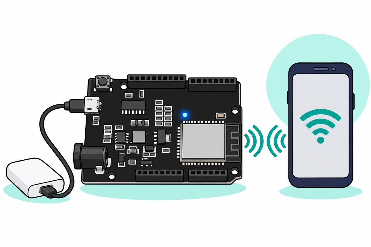
Away from a computer, a USB charger or power bank runs the board, or our 9V 2A adapter in the DC jack. The jack feeds a 5V regulator, so it needs more than 5V. 9V sits inside the board’s 5 to 12V rating (Handson Technology datasheet, barrel jack guide). Next project: the ESP32 web server relay.
If the upload fails on this board
The WEMOS D1 R32 has no BOOT button to hold. Try these in order.
- Unplug every shield and jumper, which clears anything holding A0 high or driving D0 and D1.
- Set Tools > Upload Speed from 921600 to 115200. Each bit then lasts eight times longer, which a marginal cable can still carry.
- Still stuck on “Connecting…”? Set download mode by hand. The chip enters it when IO0 is low at reset, and IO0 is the first bottom-row socket, at the DC jack end. Count twice first: counting from IO0, the second and fifth sockets carry 5V, over the 3.6V pin limit. Push a jumper from IO0 to GND (the sixth or seventh socket), tap reset, then click Upload. Afterwards pull the jumper and tap reset, or the board stays in download mode.
FAQ
Is the WEMOS D1 R32 the same as an Arduino Uno?
No. The outline and socket positions match, but the chip is an ESP32 with WiFi and Bluetooth, and its pins work at 3.3V. Check a 5V shield before fitting it.
Does the WEMOS D1 R32 have a BOOT button?
No, only a reset button. Uploads start by themselves through the CH340’s auto-reset circuit. If one will not start, jumper IO0 to GND, tap reset and upload, then remove the jumper and tap reset.
Can I use a 5V sensor with the WEMOS D1 R32?
Yes. Power it from the 5V socket, then divide its output: 10k in series, then two 10k in series from the pin to GND. That turns 5V into the 3.3V a pin can take.
Last updated November 2026. Stuck? Chat with us on WhatsApp.
