

Tutorials
XL4016 8A Buck Converter: Real Current, Heatsinks and Wire Size
Nov
To set up an XL4016 8A buck converter, set its output voltage with a multimeter while nothing else is connected, feed it 1.5–2V more than you want out, and plan on about 4–5A continuous on its stock heatsinks — the 8A/300W headline needs a fan on those heatsinks and thick wire. Here is the arithmetic behind each number.
What is the XL4016 buck converter module?
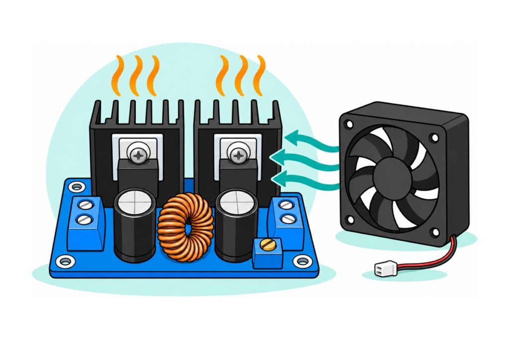
The XL4016 module is the big sibling of the LM2596 board most makers start with, built around XLSEMI’s XL4016: a 180kHz buck converter with an internal 8A power MOSFET. You can read its ambitions off the board: two finned heatsinks — one bolted to the XL4016 itself, one to the output rectifier — a bare copper toroid between them, and screw-terminal blocks at both ends. One multi-turn trimmer marked Radj sets the voltage; this is the plain constant-voltage version, no current knob, no display. That means only the chip’s own protection — a switch limit around 10A plus short-circuit frequency foldback — caps what a stalled motor or a short can pull. It also only steps down: raising voltage is a job for a boost converter.
| XL4016 module | At a glance |
|---|---|
| Input | 8–40V DC — 8V is the rated minimum; stay a few volts under 40V |
| Output | Adjustable 1.25–36V via the Radj multi-turn trimmer |
| Current | 8A chip rating, reachable with a fan; about 4–5A continuous on the stock heatsinks |
| Efficiency | Up to 96%; 93% typical at 24V in, 12V out, 6A |
| Protection | Thermal shutdown, ~10A switch current limit, short-circuit frequency foldback (180→48kHz) |
| Terminals | Screw blocks both ends, ‘+’ marked beside each |
The chip figures come from XLSEMI’s XL4016 datasheet (Rev 1.2); the continuous figure is derived below. 8V is the lowest input XLSEMI rates the chip for and 40V the top of its operating range, so keep a few volts under it — and 8A rates the silicon, not the board: heat decides what it sustains.
Parts list: XL4016 high-current buck setup
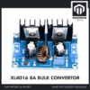 LM2596S DC-DC Buck Converter Step Down Power Module 4-40V to 1.25-37V Voltage Regulator Board - XL4016 8A BUCK CONVERTOR
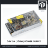 5V 12V 24V Power Supply 5A 10A 15A 20A 25W 50W 75W 120W 240W AC DC Convertor LED Strip Driver - 24V 5A (120W) POWER SUPPLY
 XL830L Digital Multimeter with backlight Portable Multimeter Electronics Project
Optional: cooling and hands-free metering
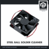 DC Cooling Fan 5V/12V Brushless Small Fan for 3D Printer DIY Projects Electronics Cooling - 8025 FAN (12V)
 Crocodile Clip Cables 46cm Alligator Clip Cable Multi Color
The 8025 fan is the price of running past 5A continuously — point it at the two heatsinks from a 12V rail. The crocodile leads hold the meter on the output terminals while both hands work the trimmer; they are meter leads only, never the load path.
How do you wire the 24V supply safely?
The 24V 5A enclosed supply is the LED-driver style of PSU: a perforated steel brick with a screw-terminal strip under a clear flip-up cover at one end, and no mains cord in the box — you fit your own 3-core cable.
This is the one mains step in the whole build, so treat it as mains. If you have never wired a plug, have someone who has check it. Work with the plug out of the wall, every time. Check that the 110/220V selector switch (the yellow sticker on the lid flags it) sits at 220V: in the 110V position the input stage runs as a voltage doubler, so Malaysia’s 230V puts roughly twice the design voltage on its input capacitors and they fail violently. Strip only enough insulation for each screw to grip, clamp every strand, and connect earth: the case is metal, and the earth wire is what keeps it at 0V if anything inside ever fails. Fit a 3A fuse in the plug and cable-tie the cord to the supply so a tug never reaches the screws.
Close the clear cover before plugging in: once live, the L and N screws carry full mains. The next step puts a screwdriver in your hand, so keep it, the crocodile clips and your fingers clear of those screws while you adjust the converter.
| Cord core | PSU terminal |
|---|---|
| Brown (live) | L |
| Blue (neutral) | N |
| Green/yellow (earth) | ⏚ (earth symbol) |
| To converter IN+ | V+ |
| To converter IN− | V− |
Everything past V+ and V− is safe 24V DC. Why 24V for a 12V project? Headroom, covered next, and watts: a 12V 5A load is 60W, roughly a 65W draw — under 3A from this 120W supply. Prefer a plug-top adapter? It still has to clear the headroom rule below; our DC power supply guide covers choosing one.
How do you set the output voltage with no load first?
The XL4016’s output terminals should hold nothing but meter probes at first power-up. The trimmer arrives wherever it was last turned, and a buck converter can put out anything up to just under its input — on the 24V supply, anywhere up to about 23V. At this current class a wrong preset is not a flicker: it is 20V-plus into your 12V load with 8A behind it. No-load-first is the safety step here, not a ritual.
Clip the crocodile leads onto the OUT terminal screws — red on the side marked ‘+’ — and the other ends onto the probes of the XL830L multimeter, set to the 200V DC range at first: a fresh board fed 24V can sit above 20V, which the 20V range shows only as a lone ‘1’. Power on, read, and turn the brass screw of the Radj trimmer. Silent turns are normal on this multi-turn part: a set point above what 24V can deliver leaves the output pinned just under the input until you bring it back below, and at either end of its travel the screw just idles, at most with a faint click, instead of hitting a hard stop. Direction varies between batches, so if many turns change nothing, reverse. Once under 20V, switch to the 20V range and walk it to 12.0V. Turning down, pause a few seconds after each nudge: with nothing connected, the output capacitor drains only through the feedback resistors, so the number lags the screw.
What the screw moves is a feedback divider: the chip holds its FB pin at 1.25V and switches harder or softer until the divider’s tap sits there, so each turn rewrites the output-to-reference ratio — the same mechanism as in our LM2596 guide. New to the meter? Start with how to use a digital multimeter.
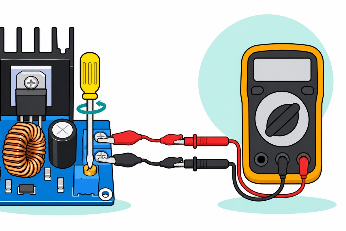
Only now does the load go on: switch off at the wall, wire the load ‘+’ to ‘+’ with proper power wire (the wire section below says which), re-check the input polarity — a reversed input is one of the quickest ways to kill a buck module — then power up and re-read the voltage at the load’s own terminals while it runs.
What input voltage does the XL4016 need for 12V out?
For 12V out under load, give the XL4016 15V or more in. Its datasheet lists a 0.3V minimum dropout but ties it to no load current, and dropout grows with current. With the switch fully on, the output is the input minus every series drop: the MOSFET’s 40–50mΩ on-resistance costs around a quarter volt at 5A, the toroid’s winding and the wiring take their share, and the supply itself sags under load. The moment the input minus those drops touches your set point, the duty cycle hits 100% and regulation ends — the output then follows every dip and ripple on the input.
Those drops also grow as the board warms, because the switch’s on-resistance climbs with temperature, and the supply ripples as well as sags. Leave margin for all of it: the practical rule at amps is 1.5–2V of headroom, which is why XLSEMI’s own 12V/6A test circuit in the XL4016 datasheet is specified for 15–40V in. It is also why a 12V 2A plug-top adapter can never feed a regulated 12V output — you get the adapter’s voltage minus a few tenths, unregulated, wobbling with every dip, and at 24W it could not carry a 5A load anyway — and why a 12V 5A+ build starts from a 15V-or-higher source. The 24V supply clears the rule with margin.
How much current can the XL4016 really deliver?
The XL4016 board’s limit is thermal, and you can derive it on an envelope. The datasheet’s efficiency for 24V in, 12V out is 93%: every 100W delivered leaves about 7.5W of heat on the board. At this ratio the internal MOSFET conducts half of each cycle, dropping ~0.25V at 5A; the Schottky rectifier — the part on the second heatsink — conducts the other half at ~0.5V; switching losses in the XL4016 and the toroid’s copper and core take the rest. That is why the rectifier earned a heatsink of its own.
Now run the numbers. At 5A and 12V out you deliver 60W and make about 4.5W of heat. Split all of it, conservatively, across the two heatsinks — small bolt-on fin sinks like these manage very roughly 12–15°C per watt in still air — each tower rises about 30°C over a 33°C Malaysian room: 60-something-degree metal, hot to touch and entirely fine. At 8A you deliver 96W, efficiency slides a few points, and dissipation roughly doubles to 9–10W: the sinks climb 60–70°C, the junctions behind them run hotter still, up to the 125°C maximum operating junction temperature in the datasheet. Past that the XL4016 protects itself — its built-in thermal shutdown cuts the output, the board cools, the output returns — so the chip does not die on the spot, it cycles. The rectifier and capacitors beside it have no such protection and bake on every cycle, so treat cycling as a warning, not a feature. That is the whole story behind the 8A headline: about 4–5A is the honest continuous ceiling in still air, and the 8025 fan is the price of more — forced air cuts a fin sink’s thermal resistance to roughly a third, which puts 8A back inside the ceiling.
Why stop at 4–5A when 6A would only take the metal to around 70–80°C? Because an open bench is the best case: inside a closed box the surrounding air can warm another 10–15°C, and the electrolytic capacitors beside the heatsinks lose roughly half their life for every 10°C hotter they run. Mount the board on standoffs through its four corner holes, never flat on metal, which would short the solder joints underneath.
The 300W headline deserves the same treatment: watts are volts times amps, so 300W assumes 8A at a 36V-class output. At 12V out, 8A is only 96W — at hobby voltages you run out of amps long before watts.
The 8025 fan is a 12V part. In the 24V-in, 12V-out build it runs from the XL4016’s own output once the voltage is set: snip off its small white plug, twist the red lead in with the OUT+ load wire and the black with OUT−, and point the arrow moulded on its frame at the fins. A 24V build set to 5V has no 12V rail for it — one more reason the 5V route below starts from the 12V supply, with the fan across the input.
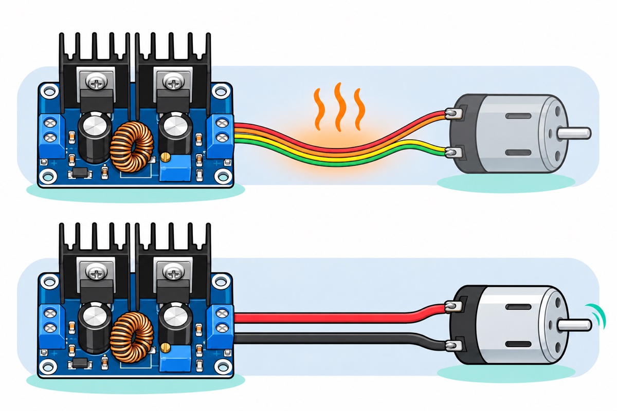
What wire carries 5A without cooking?
The XL4016’s screw terminals will happily clamp the Dupont jumpers every Arduino drawer holds — and at 5A those jumpers are the wrong part. A jumper’s conductor is roughly 28AWG: about 0.21Ω per metre. Two 20cm leads make 0.086Ω of round trip, at 5A Ohm’s law collects 0.43V — your carefully set 12.0V arrives as 11.6 — and I²R turns 2.1W loose inside two spaghetti-thin PVC sleeves and their ~1A crimp pins. Jumpers are signal wire — the same reason the crocodile leads serve the meter only.
| Wire | Cross-section | Resistance | Lost over 2×20cm at 5A | Verdict at 5A |
|---|---|---|---|---|
| Dupont jumper (~28AWG) | ~0.08mm² | ~0.21Ω/m | 0.43V, 2.1W | No — signals only |
| Thin hookup (22AWG) | ~0.33mm² | ~0.053Ω/m | 0.11V, 0.5W | Marginal, short runs |
| 18AWG stranded | ~0.8mm² | ~0.021Ω/m | 0.04V, 0.2W | Yes |
| 1.0mm² auto cable | 1.0mm² | ~0.017Ω/m | 0.03V, 0.2W | Yes, with margin |
Those figures are for 20cm leads, and the drop grows with length: each metre of 1.0mm² red-and-black pair costs about 0.17V at 5A, so an LED strip 3m away sees half a volt less than you set. Keep the converter near the load, or step up to 1.5–2.5mm² for long runs.
Any hardware store’s 1.0mm² (about 18AWG) stranded auto or speaker cable in red and black is the right wire for every power run here. Twist each stripped end tight so no stray strand bridges the terminal block, and tug-test after tightening. If you measure current, heed what the XL830L prints beside its 10A socket: that input is unfused. Move the red lead back to VΩmA before the next voltage reading — a lead left in the 10A socket across a supply is a dead short with no fuse to save it.
Which buck converter does your project actually need?
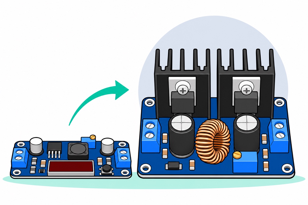
The XL4016 tops a family, and the honest buy is often one step below it. The same derating logic — roughly a watt of heat per amp at these voltage ratios — applies to every member; what separates them is the metal available to shed it.
| Module | Headline | Sustained, no fan | Heat hardware | Best fit |
|---|---|---|---|---|
| LM2596 | 3A | ~2A | None — bare board | Sensors, MCUs, small LED work |
| XL4015 | 5A | ~3A | None — PCB copper only | Single motor driver, mid-size loads |
| XL4016 | 8A | ~4–5A | Twin heatsinks, fan option | LED strips, multi-motor, bench rail |
One catch before stepping down to the XL4015: its board has bare solder pads, not screw terminals, so its power wires get soldered on.
Two jobs the XL4016 does well: a 12V motor rig — set 12.0V and feed an L298N motor driver — and high-current 5V pixel builds. For WS2812 strips, pair it with the 12V 20A supply rather than the 24V one: stepping 12V to 5V keeps the rectifier conducting a smaller slice of each cycle than 24V-to-5V, so the same amps make less heat.
Common mistakes we see
Declaring the trimmer dead after three turns. Silent turns are normal on a multi-turn trimmer, and at either end the screw just idles, at most with a faint click, instead of hitting a hard stop: keep turning, and if many turns change nothing, reverse.
Connecting the load before setting the voltage. The trimmer can sit anywhere up to nearly the full input voltage, and first power-up delivers that to anything already wired to OUT. Meter first, load second, every board.
Feeding 12V in and expecting 12V out. Dropout grows with current and the supply sags too, so plan on 1.5–2V of headroom at amps: from 12V in, about 10–10.5V is the most you can keep regulated. Set 12V anyway and the output just trails the adapter.
Blaming the board when it cuts out every few seconds under load. Rhythmic on–off–on is thermal shutdown doing its job, not a defect, but do not leave it cycling. Add the fan, or stay under 5A.
FAQ
Can the XL4016 really deliver 8A?
Yes, with cooling. The ~10A current limit is genuine silicon, but at 8A the board dissipates 9–10W and the stock heatsinks cannot shed that in still air, so thermal shutdown cycles the output. With the 8025 fan and 1.0mm² wiring 8A is sustainable; without it, treat 4–5A as the ceiling.
Why is my output voltage lower once the load is connected?
Usually wire: every milliohm between converter and load drops volts in proportion to current — thin jumper leads lose 0.4V at 5A. Measure at the load’s end and nudge the trimmer up. If the output also wobbles under load, the input is too close to the set point: restore 1.5–2V of headroom.
Can I use a 12V adapter to get 12V out?
No. A buck converter only steps down, and at real current the XL4016 needs its input 1.5–2V above the set point to keep regulating — from 12V in, about 10V out is the reliable maximum. For a regulated 12V rail, start from 15V or more; the 24V 5A enclosed supply is the clean match.
What is the difference between the XL4016 and the LM2596?
Current class and the hardware around it. The LM2596 is a bare 3A-headline board happiest near 2A; the XL4016 adds an 8A switch, a beefier rectifier and two heatsinks, and holds 4–5A continuously. The procedure — multi-turn trimmer, meter, no load first — is identical on both.
Can I charge a battery with the XL4016?
Not with this version. It is constant-voltage only, so a flat battery wired to it draws as much current as the board can push — up to the chip’s roughly 10A switch limit — instead of a controlled charge. Charging needs current control, which means a charger made for that battery type. Keep this board for fixed-voltage loads like LED strips and motor drivers.
Last updated November 2026. Stuck? Chat with us on WhatsApp.
