

Tutorials
MT3608 Boost Converter: How to Set a 5V, 9V or 12V Output
Nov
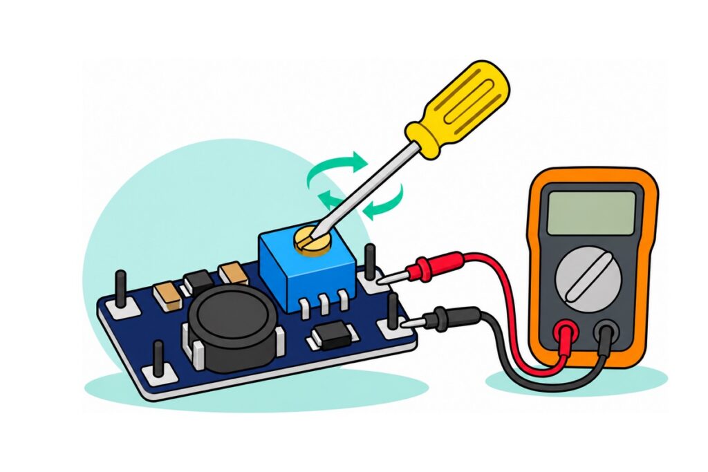
Set an MT3608 boost converter’s output before any load touches it: power the board from a single 18650 cell, put a multimeter across VOUT+ and VOUT−, and keep turning the blue trimmer — ten or more full turns is normal — until the meter reads 5V, 9V or 12V. A fresh board’s trimmer sits wherever the factory left it, which can mean up to about 28V on the output, so a 5V gadget connected before that first adjustment can die on the spot. Two rules frame the rest: keep the input below the output, and read the “2A” badge as a datasheet headline, not output current — from one cell, expect roughly 0.5–0.7A at 5V and 0.2–0.3A at 12V continuous.
When is the MT3608 the right converter for the job?
The MT3608 is a step-up (boost) converter: it raises a lower voltage to a higher one, never the reverse. Feed it 2–24V and the trimmer sets any output above that input, up to 28V, switching at 1.2MHz — the numbers are from Aerosemi’s MT3608 datasheet. Need to come down instead, say 12V to 5V? That is a buck job: our boost-vs-buck chooser settles the direction, and the LM2596 guide covers the buck-side adjustment.
The MT3608 board ships as a bare navy-blue PCB with four corner solder pads — no headers, no terminals. Snap four single pins off the 40-pin male header strip and solder one into each corner pad, long end pointing down (technique in our header soldering guide), so the module stands on a breadboard. A joined 2-pin piece will not fit: VIN+/VIN− sit at the two corners of one short edge and VOUT+/VOUT− at the other, each pair a board-width apart, far wider than the strip’s 2.54mm pitch. Prefer not to solder? The 5-pin soldering service covers all four joints.
Parts list: set up an MT3608 boost converter
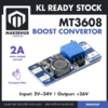 MT3608 Adjustable Step-up Convertor Boost Converter Switching Boost Converter for Arduino Project
 18650 Battery Holder 1/2/3/4 Slot 3.7V Battery Cell Housing Battery Case Battery Casing - 18650 BATTERY HOLDER (1)
 3.7V 18650 Battery Rechargeable Li-Ion Battery 1200mAh 2200mAh 3200mAh Flat Top - 18650 Li-Ion Battery (2200mAh)
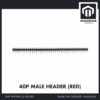 2.54mm Pin Header Female Male Single Row Header 40P Connector Black White Red Yellow Green Blue - 40P MALE HEADER (BLACK)
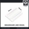 MB102 Breadboard 170 400 830 Holes Breadboard Donut Board Arduino Prototype Multi Color - BREADBOARD (400 HOLES)
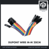 40pcs Dupont Wire 10cm 20cm 30cm for Breadboard DIY Experiment Jumper Wire Breadboard wire - DUPONT WIRE M-M 20CM
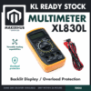 XL830L Digital Multimeter with backlight Portable Multimeter Electronics Project
Optional: XL6009 upgrade, soldering service and extras
 XL6009 Adjustable Step Up Converter Boost Converter Module XL6009E / XL6009D Display - XL6009 BOOST CONVERTOR
 Soldering Service for Circuit Boards & Electronics - 5 Pins Soldering Service
 18650 Battery Charger 1/2 Slot Li-on Battery Charger USB A Connector 3.7V Universal Charger - 18651 BATTERY CHARGER (2 SLOT)
 DC Cooling Fan 5V/12V Brushless Small Fan for 3D Printer DIY Projects Electronics Cooling - 8025 FAN (12V)
The XL6009 is the step-up for loads the MT3608's current arithmetic rules out. The 5-pin soldering service covers one module's four corner joints so it arrives ready for the breadboard. The charger tops up the 18650 between sessions, and the 12V fan is this guide's demo load.
How do you set the MT3608 to 5V, 9V or 12V?
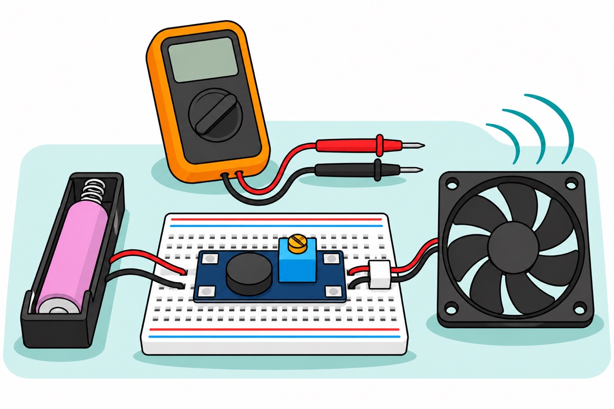
The MT3608’s input must stay below the output you are setting, so this bench uses one 18650 cell in the single-slot holder: a Li-ion cell swings 3.0–4.2V across its charge, always under even the lowest 5V target. Skip a two-slot series holder here — two full cells stack to 8.4V, above a 5V set-point, and a boost cannot regulate downward, as the next section shows. A 5V USB supply follows the same rule: fine for a 9V or 12V output, never for 5V. The holder’s thin stranded leads splay inside breadboard springs: twist each bare end tightly around the pin of an M-M jumper, with a dab of solder to make it permanent.
Build on the breadboard in this order: module first, then jumpers, battery last. Place the module across the centre gap like a chip, so each pin sits in its own five-hole strip (VIN+ and VIN− sharing one would short the cell), and plug each holder jumper into the strip of the pin it feeds. Seat the cell minus end against the holder’s spring, plus end against the brass stud — the board has no reverse-polarity protection. Reversed, the cell drives current backwards through the inductor and the switch’s built-in body diode, close to a dead short that can kill the module and overheat the cell. The pink flat-top cell is an unprotected ICR type: never let the holder’s bare leads touch, and charge it only in a proper 18650 charger (habits in our 18650 charging guide). Nothing here stops the cell running flat, either: the MT3608 keeps boosting down to about 2V, its undervoltage lockout, well past the 3.0V where a Li-ion cell should stop. Lift the cell out after use, and recharge it once the meter reads near 3.0V.
Now the multimeter, which the whole procedure happens through. Black probe in COM, red in VΩmA, dial on DC volts at the 200V position for the first look: a fresh board can sit above 20V, where the 20V range shows only an over-range flag (dial walkthrough in our multimeter guide). Probes take both hands, so work in rounds: read at the VOUT+ and VOUT− solder joints, put the probes down, give the trimmer’s brass screw a turn, read again, and drop to quarter turns near the target. Once the reading is under 20V, click down to the 20V range and land it on 5.0, 9.0 or 12.0V. Only now does a load connect.
| MT3608 pad | Connects to | Notes |
|---|---|---|
| VIN+ | Holder’s red lead (on a jumper pin) | 2–24V in, and always below the output you set |
| VIN− | Holder’s black lead | No reverse-polarity protection — double-check before the cell goes in |
| VOUT+ | Red meter probe, then the load’s + | Set the voltage before the load ever connects |
| VOUT− | Black meter probe, then the load’s − | Shares ground with VIN− on the board |
For the satisfying proof, set 12.0V and connect the 80mm 12V fan: its red-and-black lead pair ends in a small white two-pin connector that grips two M-M jumper pins directly — red to VOUT+, black to VOUT− — and it spins up on battery power. Meter VOUT again with the fan running: a reading that sags well below 12V means the load is past the limits worked out below. Everything here is low-voltage DC; what is at risk is the load and the cell, which is why the voltage is set before the load exists.
Why does the trimmer seem to do nothing at first?
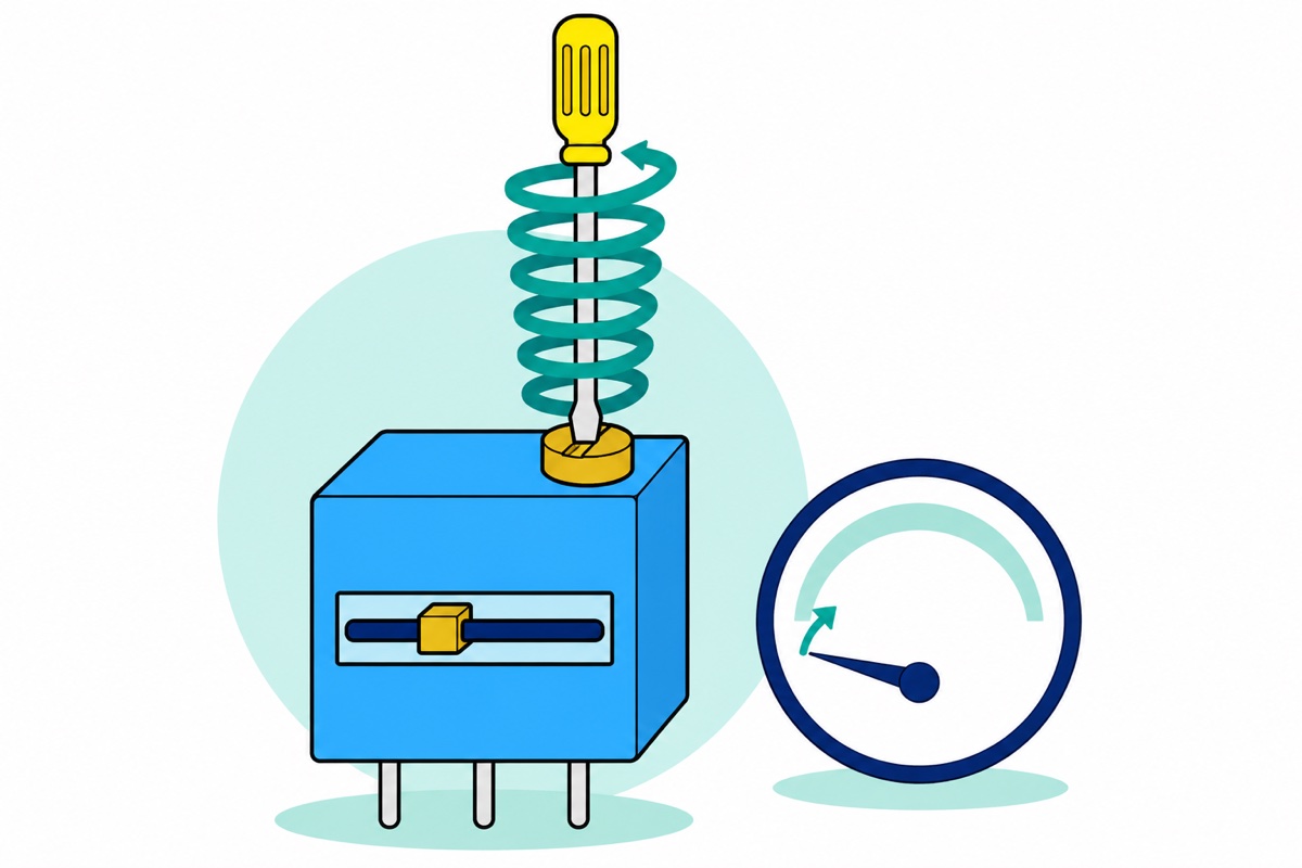
The MT3608’s blue cube is a 3296-class multi-turn trimmer: inside, the brass screw crawls a tiny nut along a long resistive track, and one full turn moves the wiper only about a twenty-fifth of the way — Bourns’ 3296 datasheet specifies 25 turns end to end. On the usual board the trimmer is a 100k part working against the small 2.2k resistor beside it (marked 222) on the chip’s 0.6V feedback pin, so the set-point is 0.6V × (1 + Rtrimmer ÷ 2.2k): about 0.6V at one end, 28V at the other, roughly 1V per full turn between. Twenty-odd turns from the top end down to 5V is normal. A turn that changes nothing has one of three causes.
The screw is past an end. Neither end has a hard stop — Bourns lists the mechanical stops simply as “wiper idles” — so a screw at its limit just keeps turning, at most with a faint click each turn. Several turns with no change? Reverse.
The meter is over-range. From the top end the output stays above 20V for the first seven or so turns, and the 20V range shows only its over-range flag — why the first look is on 200V.
The set-point is below your input. From the bottom end, the first three or so turns only lift the set-point from 0.6V to the cell’s own voltage, and the output does not move meanwhile.
Which direction lowers the voltage? Board makers wire the trimmer either way round, so ignore any clockwise rule you’ve read: turn while watching the meter, and reverse if the number climbs.
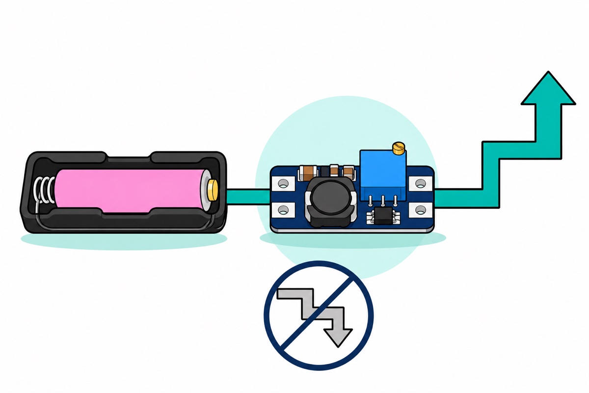
The set-point-below-input case is worth understanding properly, because it is also the input-below-output rule. A boost converter switches its inductor to ground so current builds in it, then releases it so the stored energy stacks on top of the input voltage and pushes through the output diode. Switching can only ever add — and when the chip is not switching at all, the input still flows straight through the inductor and diode to the output pads. So the output can never fall below the input minus the diode’s drop, roughly 0.3V through the board’s SS34-class Schottky. Dial the set-point below your input and the chip simply stops switching: the output pins at about Vin − 0.3V and no amount of turning changes it. This is also exactly why two series 18650s at 8.4V can never give a regulated 5V from this board.
How much current can the MT3608 really deliver?
The MT3608’s “2A” badge is the headline of Aerosemi’s MT3608 datasheet, which titles the chip a “2A Step Up Converter” — not a promise of 2A at the output. The hard limit inside that datasheet is the built-in MOSFET switch’s current limit: 4A peak. Neither number is an output rating, because a converter conserves power, not current: Vout × Iout ≈ η × Vin × Iin, with efficiency η around 85–90% for boards in this class. In a boost the input current is the larger of the two, and every amp of it flows through the small inductor and the chip’s switch — that switch limit bites exactly where current is highest, and on a chip this small, heat runs out long before the switch does.
Work it through for one 18650 at its 3.7V nominal: 3.7V × 4A caps input power at 14.8W, and 90% efficiency leaves about 13.3W at the output. Divide by the output voltage for the theoretical ceiling, then expect far less. The 4A is a typical peak, specified at 5V in and 50% duty and guaranteed by design rather than tested. Losses in the switch, the inductor’s winding and your wiring grow with the square of the current, so efficiency falls as you push; the tiny SOT-23-6 chip has little copper to shed that heat through; and the cell’s own voltage sags under heavy draw, which pushes the input current higher still. An independent bench test of this module type measured about 0.7A at 5V and 0.2A at 15V from a 3V input, with the chip near 94°C after an hour at 0.6A. Scaled to a 3.7V cell, that gives the realistic column:
| Target output (from 3.7V) | Ceiling at 4A from the cell | Realistic continuous |
|---|---|---|
| 5V | ≈2.7A | 0.5–0.7A |
| 9V | ≈1.5A | 0.3–0.4A |
| 12V | ≈1.1A | 0.2–0.3A |
Size any load the same way. This guide’s 80mm fan draws roughly 0.1–0.2A at 12V — 1.2–2.4W, or roughly 0.4–0.7A from the cell, inside the realistic 12V row. A 1A 12V LED strip is 12W: about 3.6A from the cell, close to the 4A switch peak and several times what the board sustains, so the module sags, overheats and trips its thermal shutdown, cutting out and restarting as it cools. That strip is not a faulty-MT3608 problem — it is an XL6009 job.
The same input current runs through your wiring, too: about 1A from the cell for 0.7A at 5V. Breadboard springs and 20cm jumpers are made for signal currents, so for loads near the table’s limits, solder short, thick wires straight to the pads.
When should you step up to the XL6009 instead?
The XL6009 is the same idea built bigger. Its chip lists the same 4A switch limit on paper, with 5–32V input and 400kHz switching, per XLSEMI’s XL6009 datasheet; the extra current capacity comes from the package and the board. The chip is a TO-263 power package rated 30°C/W junction-to-ambient with no heatsink, its metal tab shedding heat into the copper, beside a much larger 47µH inductor (marked 470) and electrolytic capacitors — so heat, the MT3608’s real bottleneck, has somewhere to go. A higher input voltage also cuts the input current: the same power arithmetic puts that 12V LED strip at about 2.7A from a 5V supply, 1.8A from two 18650s in series (6.0–8.4V, so 12W ÷ 0.9 ÷ 7.4V), or 1.5A from 9V, all inside the switch limit. Mind the 5V input floor, though: a single Li-ion cell sits below spec, so feed the XL6009 board from a 5V-plus source, still kept below the set output. Our board’s output capacitor is rated 50V, and keeping an electrolytic at around 70% of its rating is why 35V is the sensible output ceiling. It has the same four bare solder pads and a blue multi-turn trimmer (side screw rather than top), so everything on this page — solder, set with the meter, only then connect — transfers unchanged.
Two siblings earn a mention. The XL6009 with display swaps the pads for screw terminals and adds a 3-digit voltmeter with a select button — no soldering and no multimeter needed. For heavier loads again, the XL6019 5A-class board takes over where the XL6009’s arithmetic runs out.
Common mistakes we see
Connecting the load first, adjusting after. A fresh board’s output can sit anywhere up to about 28V; the 5V device meets that before the first turn of the screw. Nothing on the module warns you — the meter-first habit is the whole defence.
Two turns, no change, “the pot is faulty”. It is almost always one of the three causes above: the screw spinning at a slip-clutch end, the meter over-range, or a set-point still below the input. Keep the meter on and keep turning, reversing if several turns change nothing.
Boosting when the job is bucking. Wanting 5V from a 9V or 12V supply means stepping down — the wrong direction for this module entirely. Our boost-vs-buck chooser sorts it in one table.
FAQ
Can the MT3608 really output 2A?
No — 2A is the headline figure in the datasheet’s title, and the chip’s own hard limit is a 4A peak through its internal switch on the input side; neither is an output rating. Heat in the tiny package bites long before that: from a 3.7V cell expect about 0.5–0.7A at 5V, 0.3–0.4A at 9V and 0.2–0.3A at 12V continuous. Loads beyond that belong on an XL6009.
Why is my MT3608 stuck at my battery voltage no matter how I turn the pot?
Your set-point is at or below the input voltage. A boost cannot regulate downward: with the chip not switching, the input flows through the inductor and diode to the output, which pins at about the input minus 0.3V. Raise the set-point above the input, or power the board from a lower source.
Which direction do I turn the trimmer to raise the voltage?
There is no universal answer — board makers wire the 25-turn trimmer either way round. Connect the multimeter to VOUT+ and VOUT− first, turn slowly, and let the reading tell you; reverse if it moves the wrong way. Expect many full turns, especially on a fresh board.
Can I power the MT3608 from two 18650s in series?
Only when the output sits clearly above the pack’s full-charge 8.4V — yes for a 12V set-point, never for 5V, and 9V leaves just 0.6V of headroom at full charge, too tight to rely on. For 5V work, one cell is the right input.
What is the difference between the MT3608 and the XL6009?
Both are adjustable boost converters set the same way. Both chips list a 4A switch limit; the package and the board are the difference. The MT3608 is a tiny SOT-23-6 with a small inductor, taking 2–24V in; the XL6009 takes 5–32V in and sits in a TO-263 power package beside a 47µH inductor and electrolytic capacitors, so it sheds heat far better and sustains much more output current. The screw-terminal XL6009D adds a voltmeter, so no soldering or multimeter is needed.
Last updated November 2026. Stuck? Chat with us on WhatsApp.
