

Tutorials
Choosing a DC Power Supply: Volts, Amps and Barrel Jacks
Aug
The amp rating on a DC power supply is a ceiling your project draws from, not a force pushed into it — so match the voltage exactly and buy the amps generously. 5 V goes to a 5 V rail; 7–12 V goes into a barrel jack, because a regulator sits behind it.
Do you buy a 5 V supply or a 12 V one?
A DC power supply is chosen by the project, never by the socket it plugs into. A customer building lights and fans on one board put it in one line: “So kene beli 5v ke 12v” — so do I buy 5 V or 12 V. The answer is never on the wall. It is on the thing being powered.
Read it off in a fixed order. Voltage first: what does each part need at its input? Let the fussiest one decide. Current second: add up what those parts draw, and buy above the total. Connector last — a cheap adapter cable can undo that choice; the other two it cannot.
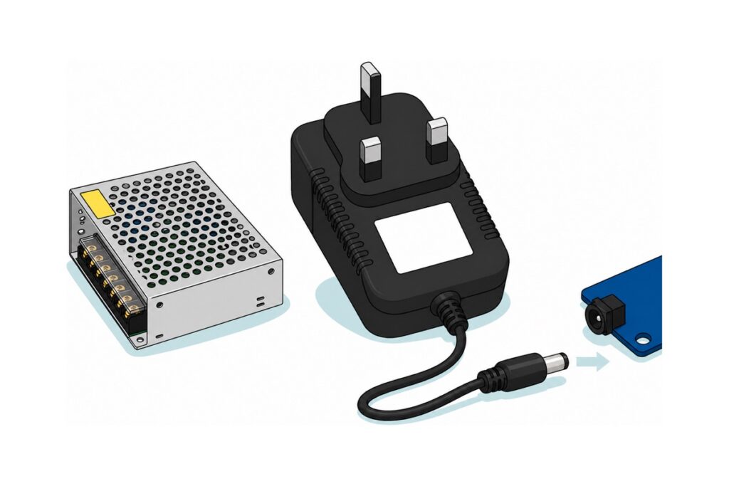
Four voltages cover almost every bench. A 5 V power supply feeds anything already built for a 5 V rail: 5 V LED strip, small pumps, relay coils, a board through its 5 V input. A 9 V power supply is the barrel-jack answer for an Uno-style board, because a regulator behind that jack needs headroom. A 12 V power supply suits 12 V strip, 12 V pumps, fans and most solenoid locks. A 24 V power supply appears when the load itself is 24 V — long LED strip runs, stepper drivers, industrial gear — and it is chosen because the same wattage arrives at half the current, so a long strip loses less voltage on the way to its far end. None substitutes for another: 24 V into a 12 V strip kills it in seconds, and 5 V into a 12 V pump barely turns it.
Then size the amps for the worst instant, not the average one. A motor, a pump or a solenoid pulls several times its running current the moment it starts, and that spike is what collapses a rail — so add the running currents, allow for the biggest starting load, and buy roughly a third above the total.
The choices — these are alternative lanes, not a kit to buy together
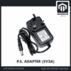 Power Supply Adapter DC Universal AC to DC Converter PSU 5V2A 5V3A 9V2A 12V2A - P.S. ADAPTOR (5V3A)
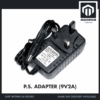 Power Supply Adapter DC Universal AC to DC Converter PSU 5V2A 5V3A 9V2A 12V2A - P.S. ADAPTOR (9V2A)
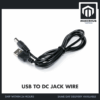 USB To 9V DC Jack Cable 5.5 x 2.1 mm 5V 9V DC Power USB Cable Connector Jack - USB TO 5V DC JACK
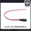 5.5x2.1mm DC Power Male Connector Plug Jack Adapter for Arduino DIY Electronics Projects - 5.5x2.1 DC CONNECTOR (F)
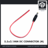 5.5x2.1mm DC Power Male Connector Plug Jack Adapter for Arduino DIY Electronics Projects - 5.5x2.1 DC CONNECTOR (M)
Pick by voltage first: the 5V 3A adapter for a 5V rail, the 9V 2A adapter for an Uno-style barrel jack, the passive USB lead for a small 5V project when a charger is already on the desk. The two 5.5 x 2.1 mm pigtails are the plumbing — the female socket gives your own project a power inlet, the male plug makes a lead that ends in a board jack. Both adapters carry a UK 3-pin plug and a centre-positive 5.5 x 2.1 mm barrel plug.
Other lanes worth knowing
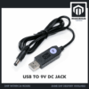 USB To 9V DC Jack Cable 5.5 x 2.1 mm 5V 9V DC Power USB Cable Connector Jack - USB TO 9V DC JACK
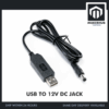 USB To 9V DC Jack Cable 5.5 x 2.1 mm 5V 9V DC Power USB Cable Connector Jack - USB TO 12V DC JACK
 5V 12V 24V Power Supply 5A 10A 15A 20A 25W 50W 75W 120W 240W AC DC Convertor LED Strip Driver - 24V 5A (120W) POWER SUPPLY
 5V 12V 24V Power Supply 5A 10A 15A 20A 25W 50W 75W 120W 240W AC DC Convertor LED Strip Driver - 5V 10A (50W) POWER SUPPLY
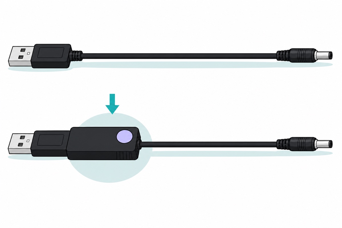
The 9 V and 12 V USB cables carry an inline boost converter, so their useful output is limited — the spec caps them at 750 mA and recommends staying at or below 500 mA. The two cage-frame bricks are the LED-strip and workshop class: mains live and neutral land on screw terminals under a clear guard, there is no plug and no barrel jack, and a 110/220 V selector switch on the case must be sitting at 220 V before the unit ever sees a Malaysian socket. Buy a plug-top adapter instead unless mains wiring is already something you do.
Why is a 5 V 5 A brick safe for a 500 mA project?
Because a regulated supply is a voltage source: it holds its voltage while the load decides the current. Ohm’s law does the deciding: a project presenting an effective 10 Ω across a held 5 V rail draws 5 ÷ 10 = 0.5 A. To force 5 A through that same 10 Ω, the supply would have to raise the rail to 50 V — precisely what a regulator prevents.
So the amp figure is a ceiling: the most the supply can hand over before its output sags. Our 5 V 10 A cage brick feeding a 500 mA project delivers 500 mA and leaves 9.5 A untouched — its 50 W badge is 5 V × 10 A, the rating, while the project consumes 5 V × 0.5 A = 2.5 W. The other 47.5 W is never generated. It also comes as a 5 V 5 A unit.
Undersizing is the failure that actually happens. Ask a 5 V 500 mA phone charger for 700 mA and it cannot hold 5 V: the rail droops, and a microcontroller resets or a radio module drops mid-job. Those symptoms read like a software bug, which is why our SIM800L brownout guide is about power, not code.
Why does 5 V into an Arduino’s barrel jack brown out?
Because the jack and the 5 V rail are two different doors into the board. On an Arduino Uno the jack does not touch that rail directly: the supply passes a reverse-polarity diode, then a 1117-family linear regulator — Arduino’s own UNO R3 datasheet lists an SPX1117 in the 5 V version — and each takes its cut. The diode costs roughly 0.7 V. The regulator needs about 1.1 V more at its input than it delivers: the SPX1117 datasheet specifies 1.0 V of dropout at 100 mA rising to 1.1 V at 800 mA. That margin is its dropout voltage, and below it the regulator stops holding 5 V.
Add those up and Arduino’s own recommendation falls out: 5 V out + 1.1 V dropout + 0.7 V diode ≈ 6.8 V, which is where the 7 V minimum comes from. Feed the jack 5 V and the regulator sees about 4.3 V, well inside dropout, so the rail lands in the low fours. The ATmega328P’s maximum-frequency curve runs linearly from 10 MHz at 2.7 V to 20 MHz at 4.5 V, so the Uno’s 16 MHz clock is still legal down to about 3.8 V — the board rarely dies outright. It runs with nothing in reserve instead, and every sensor, display and card module sharing that rail is short of its own 5 V too, which is worse, because it behaves like a flaky sketch. A jack will physically accept 5 V and the board’s power LED will even light on it, which is how the figure gets passed around; lighting up and regulating are two different claims.
The upper limit has a mechanism too. A linear regulator throws the surplus away as heat: (Vin − 5) × I. At 12 V and 200 mA that is 7 × 0.2 = 1.4 W in a surface-mount package already warm to the touch; at 20 V the same current makes 3 W and thermal shutdown cuts in. Hence 7–12 V — not 5, not 24: the board’s datasheet puts the absolute VIN limit at 6–20 V, and 7–12 V is the part of that range where the board works rather than merely survives.
Leaving the USB lead plugged in alongside the adapter is safe, and it is the first thing everyone asks when a project moves off the laptop. An Uno-style board will not let the two sources fight: a comparator watches the jack voltage behind the protection diode and, once it passes roughly 6.6 V, switches off the P-channel MOSFET that had been feeding USB 5 V to the board’s rail. The adapter then powers the board, the USB lead carries only data, and nothing back-feeds your laptop’s port. Below that threshold the switch stays on and USB keeps the rail — one more reason a 5 V adapter in the jack achieves nothing.
That also settles the tempting shortcut of putting 5 V straight onto a board’s 5 V pin: it enters behind the diode, behind the regulator and behind that selector, so nothing at all stands between your adapter and the microcontroller if the polarity or the voltage is wrong. On a board that has a jack, use the jack. On a board that has none — most ESP32 and ESP8266 dev boards — that 5 V pin is the 3.3 V regulator’s own input, and it is the intended door. An Arduino Nano is the exception to watch: its 5 V pin is its regulator’s output, so feed its VIN pin instead and the 7–12 V rule above applies there too.
| What you are powering | Supply | Where it lands |
|---|---|---|
| Uno-style board through its barrel jack, or an MB-102 breadboard supply (6.5–9 V in) | 9 V 2 A adapter | Straight into the jack — 9 V clears dropout with room to spare |
| A 5 V rail: strip, module, an ESP32 board’s 5 V pin | 5 V 3 A adapter | Into a female barrel socket pigtail, red to +, black to − |
| A 12 V LED strip or 12 V pump | A 12 V brick, or the 12 V USB cable for small loads | To the strip’s own +/− terminals |
| A DC rail you already have and need to change | A buck or boost module, not a wall supply | See boost versus buck |
| No wall socket at all | Cells, not a supply | See AA cells for projects |
One rule appears the instant a project has two supplies — a 9 V adapter for the board, a 12 V power supply for a strip. Join their negatives. A signal voltage is only a difference measured against a reference, so a control wire crossing to a driver, a MOSFET gate or a relay input means nothing, and frequently has no return path at all, unless both sides sit on the same 0 V. Positives never join; negatives always do. The one deliberate exception is hardware built to keep them apart, such as an opto-isolated relay board with its jumper removed, which our relay safety guide covers.
Which DC plug fits: 5.5 × 2.1 mm or 5.5 × 2.5 mm?
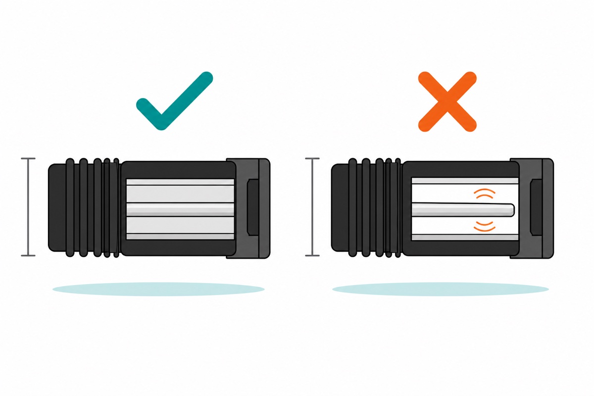
A 5.5 mm DC connector comes in two bores that look identical from outside: 5.5 × 2.1 mm and 5.5 × 2.5 mm. Both share the same 5.5 mm outer shell, so both slide into the same DC socket mouth. What differs is the bore up the middle of the plug — 2.1 mm or 2.5 mm — and that bore has to grip the socket’s centre pin, because the grip is the positive contact. Push a 2.1 mm plug onto a 2.5 mm pin and it will not seat; you feel it stop, and loud failures are safe failures. The trap runs the other way: a 2.5 mm plug slides fully onto a 2.1 mm pin, the outer shell seats so the negative connects perfectly, and the centre pin rattles in a bore 0.4 mm too wide. The project half-works, flickers when the cable is nudged, or resets when the motor starts — while looking fully plugged in.
The Uno’s jack is 5.5 × 2.1 mm, and so are both of our plug-top adapters, the male pigtail and the female one — standardise there and a drawer of adapters stays interchangeable. The 5.5 × 2.5 mm size turns up on routers and LED gear, so name both numbers when you buy. DigiKey shows the measurement:
Polarity is the plug’s other half. Both of our adapters print the standard glyph on the label: a ring with a line from ⊕ to the centre dot and from ⊖ to the outer sleeve — centre-positive, which is what an Uno’s jack and nearly every hobby board expect. Reverse it on a board with no protection diode and the regulator is gone before you notice; on an unmarked plug, a multimeter between sleeve and centre settles it.
Make that reading a habit on any lead you assemble yourself, before it ever reaches the project. Plug the adapter in, set a multimeter to DC volts, and touch the probes to the pigtail’s two bare ends, red probe on the red wire: you want the voltage you paid for, with a plus sign in front of it. Ten seconds, and it catches both the wrong adapter pulled out of a drawer and a lead wired the other way round.
When is a USB-to-DC-jack cable enough?
The USB-to-5 V-jack cable is passive: USB-A at one end, a 5.5 × 2.1 barrel plug at the other, nothing in between. For a 5 V project on a real charger or a power bank, it is the neatest answer here.
The 9 V and 12 V versions are a different animal, and you can see it: a rectangular black block sits inline behind the USB plug. That block is a boost converter, and a boost converter cannot create power — it trades current for voltage. Ignoring losses, 5 V × Iin = 12 V × Iout, so 500 mA out of the 12 V end needs 1.2 A in, and about 1.4 A at a realistic 85 % conversion. Push it to the cable’s 750 mA ceiling and the input demand passes 2 A — more than a typical USB port gives. Hence 500 mA as the working figure.
A microcontroller, a few sensors, a small display: a cable is enough, and our water level controller runs on exactly that. A motor, a pump, a metre of LED strip: it is not, and no cable will make it so.
How is a wall brick different from a buck or boost module?
A buck or boost module changes a DC voltage you already have, which is a different job with its own guide — adjusting an LM2596 down to 5 V. A switching brick starts at the mains: 240 V AC is rectified to roughly 340 V DC, chopped at tens of kilohertz through a small high-frequency transformer, and rectified again on the far side. That transformer is the point — it is an isolation barrier, and it is why the DC leaving a brick is safe to hold while the wire going in is not.
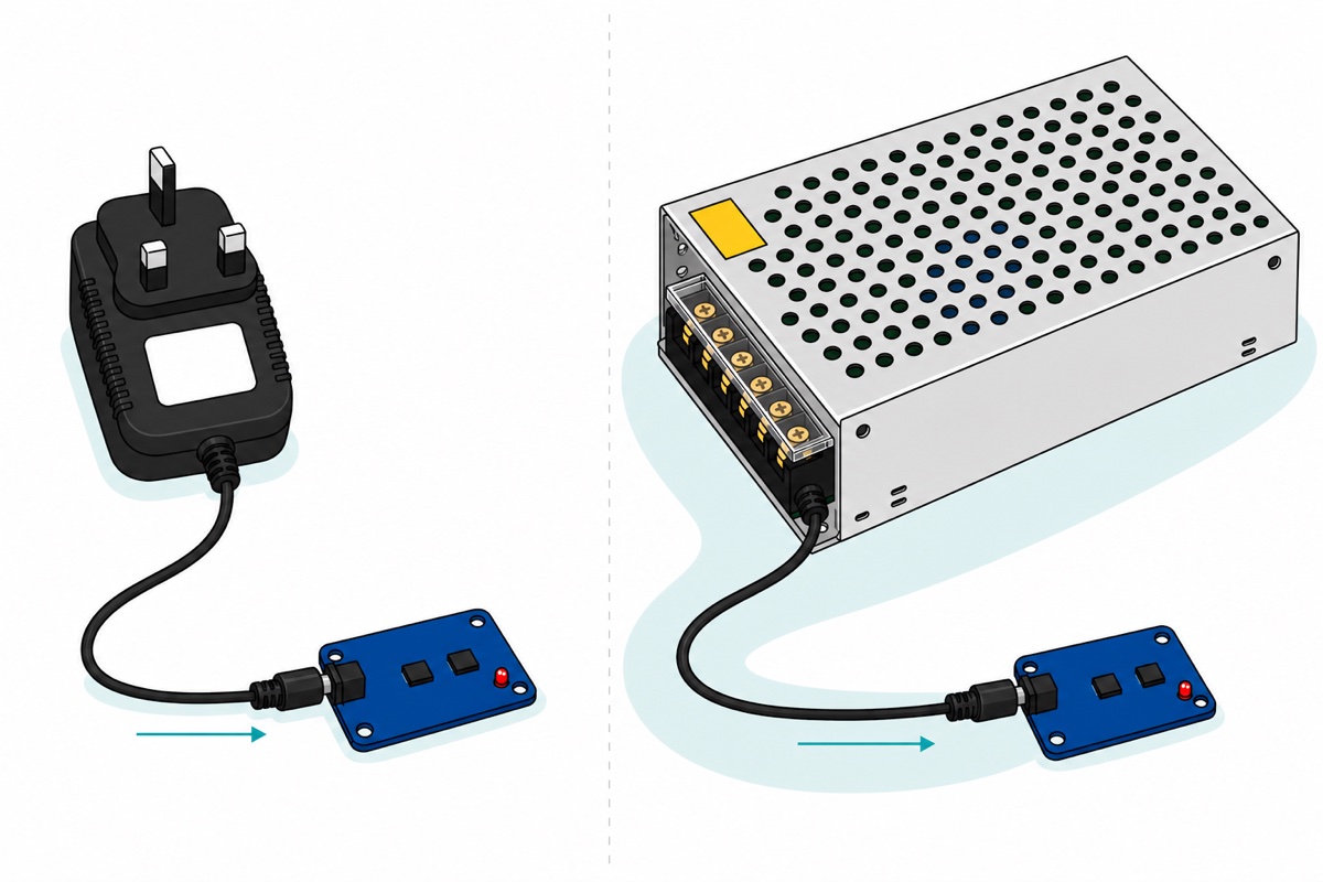
The plug-top shape — PSA0503, PSA0902 — seals that barrier inside a moulded body with a UK three-pin plug and a finished barrel lead, so nothing on the mains side is reachable. The cage-frame shape — 24 V 5 A, 5 V 10 A — is the LED-strip and workshop class, with live, neutral and earth on screw terminals and a mains lead you must make yourself — and the earth terminal is not decoration, because the frame those terminals sit in is bare metal. Its label reads 110/220 V ±15 %, chosen by a switch on the case: the 220 V setting covers Malaysia’s 240 V (220 × 1.15 = 253 V) and the 110 V setting is nowhere near it, so check that switch before the unit sees a socket. If mains wiring is not already part of your week, buy the plug-top — our relay safety guide draws the same line.
Notice what a 10 A brick does not have: a barrel jack. Its output leaves on screw terminals because a 5.5 mm barrel connector and a thin pigtail lead are a small-current path, sized for a board and its logic rather than for a motor or a metre of LED strip. So take the heavy load straight off the terminals in wire that suits it, and if a board in the same project wants a barrel jack, make that one lead with the male 5.5 × 2.1 pigtail: red to V+, black to V−, plug into the jack. That is what the male pigtail is for.
How do you prove the supply is holding up?
An Uno can measure its own 5 V rail with no extra parts. Run it with a 7–12 V adapter in the jack and the USB lead in for the Serial Monitor: the board’s power selector has already handed the rail to the adapter, so the number on screen is the adapter’s rail, not the laptop’s. The ATmega328P holds an internal 1.1 V bandgap reference; measure that known 1.1 V against the rail rather than the other way round, and counts = 1023 × 1.1 ÷ rail, so rail = 1023 × 1.1 ÷ counts. The bandgap is specified as 1.0–1.2 V, so the absolute figure runs a few percent loose — the change under load does not, and that change is the test. Compiles to 2,464 bytes.
// Rail sag meter - measures the Uno's own 5V rail using nothing but the chip
// itself. No probes, no divider, no extra parts. Upload it, then switch on
// whatever your project actually drives - motor, pump, LED strip - and watch
// the LOWEST line. A rail that dips while the load runs is a supply running
// out of ceiling, not a bug in your sketch.
//
// How it can measure its own supply: the ATmega328P carries an internal
// 1.1 V bandgap reference. Normally the ADC compares an unknown pin against
// AVcc. Here it does the opposite and compares the KNOWN 1.1 V against AVcc,
// so a full-scale reading of 1023 corresponds to AVcc, and
//     counts = 1023 * 1100mV / AVcc   ->   AVcc = 1023 * 1100mV / counts
// The bandgap is only specified to 1.0-1.2 V, so treat the absolute number as
// +/- a few percent. The CHANGE when the load switches on is the honest part,
// and the change is the whole test.

const long BANDGAP_mV = 1100;   // nominal internal reference, in millivolts
long lowest = 32000;            // running minimum, in millivolts

long readRailMillivolts() {
  // REFS0 = AVcc is the reference. MUX3:0 = 1110 selects the 1.1 V bandgap.
  ADMUX = _BV(REFS0) | _BV(MUX3) | _BV(MUX2) | _BV(MUX1);
  delay(3);                     // the reference mux needs time to settle
  ADCSRA |= _BV(ADSC);          // throwaway conversion after switching the mux
  while (ADCSRA & _BV(ADSC)) { }
  (void) ADC;

  ADCSRA |= _BV(ADSC);          // the real conversion
  while (ADCSRA & _BV(ADSC)) { }
  long counts = ADC;
  if (counts == 0) return 0;    // never divide by zero
  return (1023L * BANDGAP_mV) / counts;
}

void setup() {
  Serial.begin(9600);
  analogReference(DEFAULT);     // make sure AVcc is the reference before we start
  Serial.println(F("Rail sag meter. Switch your load on and off and watch LOWEST."));
}

void loop() {
  long mv = readRailMillivolts();
  if (mv > 0 && mv < lowest) lowest = mv;

  Serial.print(F("rail "));
  Serial.print(mv);
  Serial.print(F(" mV   lowest "));
  Serial.print(lowest);
  Serial.print(F(" mV   "));
  // 4500 mV is the bottom of a nominal 5V rail (5V - 10%) and of the
  // ATmega328P's own 4.5-5.5V speed band. The chip alone would still clock
  // 16 MHz nearer 3.8 V - nothing else on the rail is that forgiving.
  Serial.println(lowest < 4500 ? F("UNDER 4.5V - supply is sagging")
                               : F("holding"));
  delay(200);
}
Common mistakes we see from real customers
Choosing the connector before the voltage. One customer asked where the adapter should go before deciding what it should output — “atau pon untuk saya connect kan power adapter kat mane yee”. The load sets the voltage, the draw sets the amps, and the plug follows both.
Naming a voltage without naming the load. Another wrote “if i want to supply 12V, how many and which one should i take”. The “how many” half has no answer until the 12 V parts are added up — a strip plus a pump lands nowhere near a strip alone.
Assuming 5 V is 5 V. Five volts into a barrel jack is not five volts on the 5 V rail; the diode and regulator take their headroom first. Feed a jack 9 V, or a 5 V rail 5 V — never the two crossed.
FAQ
Can I use a 5 V 5 A power supply for a project that only draws 500 mA?
Yes. The supply holds 5 V while the project’s own resistance sets the current, so it draws 500 mA and the other 4.5 A is never generated. Spare amps are headroom; too few are a sagging rail.
What voltage does an Arduino Uno’s barrel jack need?
7–12 V. A reverse-polarity diode and a linear regulator sit behind it, together needing roughly 1.8 V more than the 5 V they produce, so 5 V in leaves the rail out of specification. Above 12 V the regulator overheats.
What is the difference between a 5.5 × 2.1 mm and a 5.5 × 2.5 mm DC plug?
Only the bore up the centre, on an identical 5.5 mm shell. A 2.5 mm plug slides onto a 2.1 mm pin and contacts intermittently while looking fully inserted. Arduino boards and our adapters are 5.5 × 2.1 mm.
Can a USB-to-DC-jack cable replace a power adapter?
For small 5 V loads, yes: the passive version carries the port’s 5 V straight to a barrel plug. The 9 V and 12 V versions boost, and boosting trades current for voltage, so their useful output stays near 500 mA.
How do I know whether to buy a 5 V or a 12 V power supply?
Read it off the load, not the socket. All-5 V build, buy 5 V; a 12 V strip or pump in it, buy 12 V; feeding a board’s barrel jack, buy 9 V. Then add the currents and buy above the total.
Last updated August 2026. Stuck? Chat with us on WhatsApp.

Pingback: Rocker, Toggle or Push Button: Choosing an On/Off Switch for Your Project
Pingback: Small 5V DC Fan or Fan Module? How to Choose and Drive It