

Tutorials
ESP32 DevKit V1 vs WROOM-32E vs S3 vs C3: Which ESP32 to Buy
Aug
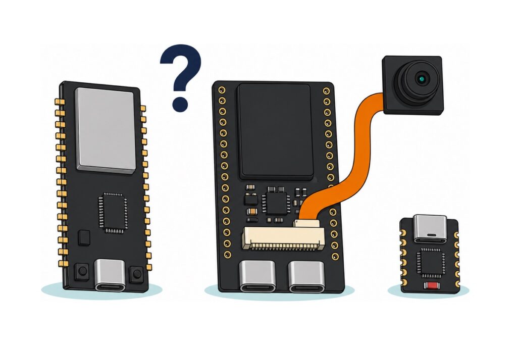
For almost every project on this site, buy the 30-pin ESP-32 (CH340) — that is the board tutorials mean when they write “ESP32 DevKit V1”, and in our catalogue it is the USB Type-C one. Take the 38-pin WROOM-32E if you want more header positions, the S3 only for camera or AI work, and the C3 Super Mini when the board has to be tiny.
Four listings here carry the same dual-core ESP32 silicon and differ only in USB chip, port shape and header length; the S3 and C3 change the chip itself. Still choosing between chip families? Our ESP32 vs ESP8266 vs Arduino UNO comparison answers that one; everything below assumes you have landed on ESP32.
Which ESP32 variant should you buy?
Every board below runs the same Arduino code for ordinary Wi-Fi, GPIO and sensor work. The differences bite at three moments: plugging the cable in, picking the board in the IDE, and running out of pins or memory.
| Board | Header positions | USB port and chip | Chip inside | Buy it when |
|---|---|---|---|---|
| ESP-32 (CH340) | 30 | Type-C, CH340 | Dual-core ESP32 | Default choice — every tutorial here fits it |
| ESP-32 (CP2102) | 30 | Micro-USB, CP2102 | Dual-core ESP32 | You already have the CP210x driver and micro-USB cables |
| ESP-WROOM-32E | 38 | Micro-USB, CH340 | Dual-core ESP32 | You want the longer header, GPIO0 and a spare ground |
| ESP-32S | 38 | Micro-USB, CH340 | Dual-core ESP32 | Same as above, with a bare gold PCB antenna beside its shield can |
| ESP32-S3 WROOM CAM | 40 (2 × 20) + camera socket | Two Type-C (UART + native USB) | Dual-core S3, 16 MB flash, 8 MB PSRAM | Camera, audio or big buffers |
| ESP32-C3 Super Mini | 16 pads (13 GPIO) | Type-C, native USB | Single-core RISC-V C3 | 18 × 22.5 mm matters more than pin count |
The six boards compared — pick ONE, these are alternatives
 NodeMCU ESP32 Wi-Fi + Bluetooth Development Board CH340/CP2012 - For IOT Project - ESP-32 (CH340)
 NodeMCU ESP32 Wi-Fi + Bluetooth Development Board CH340/CP2012 - For IOT Project - ESP-32(CP2102)
 NodeMCU ESP32 Wi-Fi + Bluetooth Development Board CH340/CP2012 - For IOT Project - ESP-WROOM-32E
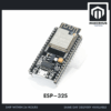 NodeMCU ESP32 Wi-Fi + Bluetooth Development Board CH340/CP2012 - For IOT Project - ESP-32S
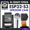 ESP32-S3 WROOM CAM DEVELOPMENT BOARD OV5640 CAMERA MODULE WIFI BLUETOOTH DUAL USB-C IOT AI
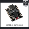 ESP32 Super Mini Ultra Small Size ESP32-C3 RISC-V Low Power Consumption - ESP32-C3 SUPER MIN
What you may also need
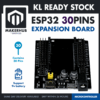 ESP32 Expansion Board 30P Expansion Board ESP32 Shield GPIO Expansion Development Kit
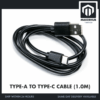 Data Cable Type-A Type-C MicroUSB Type-B 0.5m 1m 30cm 0.3m 100cm Data Transfer Upload Code - TYPE-A TO TYPE-C CABLE (1.0M)
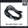 Data Cable Type-A Type-C MicroUSB Type-B 0.5m 1m 30cm 0.3m 100cm Data Transfer Upload Code - MicroUSB CABLE (1.0M)
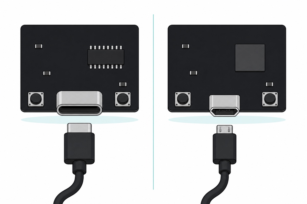
The expansion board has 30-position sockets, so it seats the two 30-pin ESP-32 boards only — the longer 38-pin WROOM-32E and ESP-32S will not go in. Take the cable that matches your board's port: Type-C for the CH340 ESP-32, the S3 CAM and the C3 Super Mini, micro-USB for the CP2102, WROOM-32E and ESP-32S. It must be a data cable; a charge-only lead powers the board but never produces a COM port.
Two of the six ship with their headers loose in the bag — the ESP32-S3 WROOM CAM and the ESP32-C3 Super Mini — so budget ten minutes with an iron and our header pin soldering guide; the other four arrive with pins already fitted. The S3 CAM’s OV5640 camera and its ribbon come in the box with it.
CH340 or CP2102 — what actually changes?
The CH340 and the CP2102 are USB-to-UART bridges, and neither is the better chip. The classic ESP32 has no USB hardware of its own — it talks over a plain serial line at 3.3 V logic, which no laptop has a socket for — so a bridge sits between the connector and the module and translates. That choice decides two things.
The driver. Each bridge is a different USB device, so your computer needs that vendor’s driver before a COM port (or /dev/tty…) appears — CH340 from WCH, CP210x from Silicon Labs. Recent macOS and Linux kernels carry both; Windows usually needs the CH340 one by hand. Once per computer, not once per board.
The cable. In our range the CH340 ESP-32 carries a USB Type-C socket while the CP2102, WROOM-32E and ESP-32S carry micro-USB. Either way the lead needs data wires in it: a charge-only cable is wired for power alone, so the bridge never enumerates and the board’s power LED lights while the port list stays empty.
Nothing else. Both boards wire the bridge’s DTR and RTS lines to EN and IO0 through the same two-transistor circuit, so both drop into the bootloader by themselves and both upload at the same 921600 baud the IDE picks by default. If the port never turns up at all, our ESP32 not detected guide works through it in order. Installing the driver looks like this:
Which board name do I pick in the Arduino IDE?
The board entry is not a label — it selects the compiler target, the flash layout and the pin map, so the wrong family produces a binary the chip cannot run. Between the four classic boards it barely matters (same silicon, same 4 MB flash); across generations it matters completely.
First the list has to exist. Arduino does not ship the ESP32 entries: open Tools > Board > Boards Manager, search esp32 and install esp32 by Espressif Systems. If nothing comes up, paste https://espressif.github.io/arduino-esp32/package_esp32_index.json into File > Preferences > Additional Boards Manager URLs and search again. That one package carries every board on this page.
| Board you bought | Entry under Tools > Board > ESP32 Arduino | Setting to change |
|---|---|---|
| ESP-32 (CH340), 30-pin | ESP32 Dev Module (or DOIT ESP32 DEVKIT V1) | None |
| ESP-32 (CP2102), 30-pin | ESP32 Dev Module (or DOIT ESP32 DEVKIT V1) | None |
| ESP-WROOM-32E, 38-pin | ESP32 Dev Module | None |
| ESP-32S, 38-pin | ESP32 Dev Module | None |
| ESP32-S3 WROOM CAM | ESP32S3 Dev Module | Flash Size 16MB, PSRAM: OPI PSRAM |
| ESP32-C3 Super Mini | ESP32C3 Dev Module | USB CDC On Boot: Enabled |
The ESP32-S3 CAM’s two settings come straight from its module marking, N16R8 — 16 MB of flash plus 8 MB of PSRAM on an octal, eight-line bus. Leave Flash Size at 4MB and the partition table is laid out for a chip a quarter of the real size; leave PSRAM on QSPI and the core probes the wrong bus, psramFound() comes back false, and a camera sketch fails at the moment it asks for its frame buffer.
The C3’s extra setting is the one that catches people. That board has no bridge chip at all — the C3 generates its own USB port in silicon — so with USB CDC On Boot disabled the core routes Serial to the hardware UART pins and your output leaves through GPIO20/21 into thin air. Enable it and the same sketch prints normally.
We also sell the ESP32-C2 (ESP8684), and it belongs in a different sentence: buy it for ESP-IDF work, not for the Arduino IDE. The Arduino ESP32 core hides its C2 entry and ships none of the C2 build libraries — the request to enable it was closed as won’t-fix — so no ESP32-C2 board appears in the Tools menu, and forcing one through fails the build.
This sketch confirms your choice in one upload. It asks the silicon what it is rather than taking anyone’s word for it, so a wrong flash size or a missing PSRAM setting shows up at once.
// WhichESP32 - ask the board itself what it is.
// Upload, open Serial Monitor at 115200 baud, press the RST/EN button.

void setup() {
  Serial.begin(115200);
  delay(2000);  // give a native-USB board time to re-enumerate before printing

  Serial.println();
  Serial.println(F("--- what this board actually is ---"));

  // Read straight out of the silicon, not out of the listing.
  Serial.print(F("Chip model    : "));
  Serial.println(ESP.getChipModel());

  Serial.print(F("CPU cores     : "));
  Serial.println(ESP.getChipCores());

  Serial.print(F("Silicon rev   : "));
  Serial.println(ESP.getChipRevision());

  Serial.print(F("CPU clock     : "));
  Serial.print(getCpuFrequencyMhz());
  Serial.println(F(" MHz"));

  // Flash size the bootloader was told to use, in whole megabytes.
  Serial.print(F("Flash         : "));
  Serial.print(ESP.getFlashChipSize() / (1024 * 1024));
  Serial.println(F(" MB"));

  // PSRAM is external RAM. Only boards carrying the extra die report any.
  Serial.print(F("PSRAM         : "));
  if (psramFound()) {
    Serial.print(ESP.getPsramSize() / (1024 * 1024));
    Serial.println(F(" MB"));
  } else {
    Serial.println(F("none"));
  }

  // Internal SRAM still free once the sketch and the Wi-Fi stack are loaded.
  Serial.print(F("Free heap     : "));
  Serial.print(ESP.getFreeHeap() / 1024);
  Serial.println(F(" KB"));
}

void loop() {
  // Nothing to repeat - press RST to print the report again.
}
A classic board answers a package name — ESP32-D0WD-V3 on current modules, ESP32-D0WDQ6 on older ones, never the bare word ESP32 — with 2 cores, 4 MB flash, PSRAM none. The S3 CAM answers ESP32-S3, 16 MB, PSRAM 8 MB. The C3 Super Mini answers ESP32-C3, 1 core.
30 pins or 38 pins — how many are really extra?
The 38-pin boards break out eight more header positions, and it pays to know what those eight are. Six of them are GPIO6 to GPIO11, wired inside the module to its own SPI flash chip — the memory your program lives in. Drive one and the chip loses its code mid-instruction and reboots, so they are exposed but not usable. The genuinely new positions are GPIO0 — the boot-select pin, which the 30-pin layout keeps on the BOOT button alone — and a third GND. The 5 V rail is on both boards; the 30-pin one simply labels it VIN.
So when a customer asks us for the board with “banyak pin”, the honest answer is one more usable GPIO and one more ground. GPIO0 works as an ordinary output once the board is running, as long as nothing holds it low at reset — that level is what the chip reads to decide whether to start your sketch or wait in the bootloader. Take the 38-pin ESP-WROOM-32E for the longer header and the roomier layout, not because eight new signals are waiting on it.
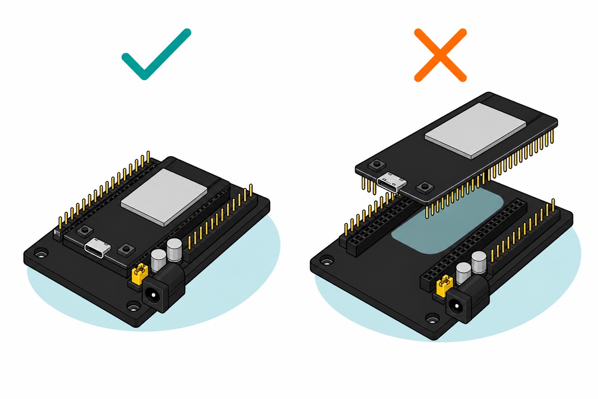
Board length decides accessories. The 30-pin expansion board has two 15-position female sockets silkscreened EN, VP, VN, D34 through D13 and GND — the 30-pin pinout exactly. The longer 38-pin boards do not seat in it, so buy that shield only with an ESP-32 (CH340) or ESP-32 (CP2102).
Classic, S3 or C3 — what does a newer generation buy you?
The classic ESP32 is the dual-core Xtensa LX6 part running to 240 MHz with 520 KB of internal SRAM, Wi-Fi, Bluetooth Classic and BLE, and — on the WROOM-32E’s default N4 build — 4 MB of flash. That is the silicon in all four classic listings, the gold-antenna ESP-32S included: LX7 cores arrived with the S3 generation, and the ESP-32S module’s own printed feature list is the classic set.
The ESP32-S3 WROOM CAM moves to two Xtensa LX7 cores with Wi-Fi and Bluetooth 5 LE only — no Bluetooth Classic, so it will not pair as an audio device. Its module is marked N16R8: Espressif shorthand for 16 MB of flash and 8 MB of PSRAM. PSRAM is why this board exists.
PSRAM is a second memory die inside the module, mapped into the chip’s address space over a dedicated bus. You need it because 520 KB of internal SRAM must hold the Wi-Fi stack, your variables and any buffer at once, while one 640×480 camera frame in RGB565 is 640 × 480 × 2 = 614,400 bytes — more than all the internal SRAM, before Wi-Fi takes its share. With PSRAM that frame comes out of megabytes instead, at the cost of slower access. No PSRAM, no camera buffer.
Its two Type-C sockets are not interchangeable: the left port runs through the UART bridge and is the one for power and uploads, while the right port is the S3’s own native USB, giving built-in JTAG debugging and letting the board present itself as a USB keyboard or drive. Either powers it.
The ESP32-C3 Super Mini goes the other way: a single RISC-V core at 160 MHz with 400 KB of SRAM, Wi-Fi and BLE 5, and 4 MB of flash inside the chip package. That last part is what shrinks the board: no separate flash die, so no shielded module either — just the bare QFN and a small ceramic antenna — and the C3’s own USB peripheral does away with the bridge chip as well. Thirteen GPIOs reach its castellated pads at 18 × 22.5 mm, but they are numbered GPIO0–10 and 20/21, so a sketch written around the classic D21/D22 labels has to be re-pointed before it will run. Two side lanes: the Uno-form ESP32 for reusing Uno shields, and the S2 Mini, which has native USB but no Bluetooth at all.
If it helps to see a spread of ESP32 boards benchmarked side by side:
Is 5 V safe on an ESP32?
Power and signals need separate answers. Feeding 5 V is correct: USB is 5 V, and the VIN or 5V pin goes to the onboard AMS1117 regulator that drops it to the 3.3 V the module runs on. The C3 Super Mini and S3 CAM take 5 V on their 5V pad the same way.
Signals are the opposite. Every GPIO is a 3.3 V pin, and the ESP32 datasheet caps a high input at VDD + 0.3 V — about 3.6 V. A 5 V sensor output wired straight to a GPIO sits well over that, so use a resistor divider or a level shifter. Our powering ESP32 projects guide covers supply.
Common mistakes we see from real customers
“Esp wroom 32e tu ch340 atau cp2102?” — CH340, with a micro-USB socket. The Type-C board in our range is the 30-pin ESP-32 (CH340), a different listing, so check the socket shape in the photo before ordering a cable.
“for this esp32 (ch340) what is the board name in arduino ide” — ESP32 Dev Module. The CH340 is the USB bridge, not the chip, so it never appears in the board list at all.
“ini ada 2 usb type C…. blh terang sikit fungsi 2 usb type c ni” — on the S3 CAM, left is the UART bridge for power and uploading, right is native USB for JTAG and USB-device work. Start with the left one.
“esp32 sy beli tu sesuai ke guna expansion ni” — only if it is a 30-pin board. Count the pins on one side: fifteen fits the shield, nineteen does not.
FAQ
Which ESP32 should I buy for a school project?
The 30-pin ESP-32 (CH340). Every ESP32 tutorial is written around its pin labels, its headers arrive already soldered, and it is the board the 30-pin expansion shield is built for.
Is the ESP32 DevKit V1 the same as the ESP-32 (CH340)?
Yes. “DevKit V1” names the 30-pin layout, fifteen pins a side, and both our 30-pin listings use it. Either selects as ESP32 Dev Module or DOIT ESP32 DEVKIT V1.
CH340 or CP2102 — which is better?
Neither. Both are USB-to-UART bridges uploading at the same speed. The choice decides which driver you install once, and in our range whether the socket is Type-C (CH340) or micro-USB (CP2102).
How much flash memory does an ESP32 board have?
The classic boards carry 4 MB, the default build of the WROOM-32 and WROOM-32E modules, of which the IDE’s stock partition scheme gives your sketch 1,310,720 bytes, about 1.25 MB. The S3 CAM has 16 MB, the C3 Super Mini 4 MB inside its chip package.
Can I connect a 5 V sensor to an ESP32?
Not directly to a GPIO. The pins are 3.3 V and the datasheet’s maximum high input is about 3.6 V, so use a resistor divider or a level shifter. Powering the board from 5 V through USB or VIN is fine.
Last updated August 2026. Stuck? Chat with us on WhatsApp.

Pingback: ESP32 Expansion Board: Do You Need One? 30-Pin Shield