

Tutorials
SX1278 Ra-02 LoRa Module with Arduino: Wiring, First Message and Real Range
Nov
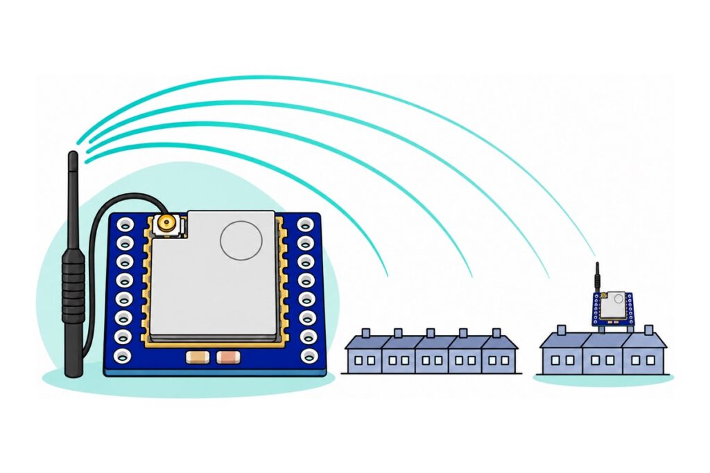
The SX1278 Ra-02 is a 3.3V-only 433MHz LoRa radio: power it from 3.3V — never 5V — click its antenna on before the board ever sees power, level-shift the four signal lines a 5V Uno drives into it, and one board can send the other its first message at 434MHz with the Arduino LoRa library. Expect hundreds of metres through a built-up taman and low single-digit kilometres in clear line of sight, in the 433–435MHz band MCMC class-assigns to short-range radios at up to 100mW EIRP.
What is the SX1278 Ra-02 module?
The SX1278 Ra-02 module is Ai-Thinker’s silver-shielded 433MHz radio on a navy breakout board: LoRa modulation, SPI interface, tuning range 410–525MHz, up to +18dBm of transmit power — the band and PA figures are etched on the shield itself.
| SX1278 Ra-02 | At a glance |
|---|---|
| Radio chip | Semtech SX1278 — LoRa, FSK and OOK |
| Tuning range | 410–525MHz; in Malaysia use 433–435MHz |
| Transmit power | Up to +18dBm; the LoRa library defaults to +17dBm |
| Supply | 2.5–3.7V, 3.3V typical — never 5V |
| Current | About 12mA receiving; 90–120mA bursts transmitting |
| Interface | SPI (NSS, SCK, MOSI, MISO) plus RST and DIO0 |
| In the bag | Breakout, two loose 8-pin header strips, U.FL whip antenna |
Why does one LoRa link use two different boards?
A first SX1278 message needs a radio at each end — the parts list carries two — but deliberately not two of the same microcontroller.
The split follows the module’s two appetites. Receiving is cheap — about 12mA, per Ai-Thinker’s Ra-02 specification — well within the Uno R3’s 3.3V pin, which Arduino rates at 50mA, so the Uno listens. Transmitting is not: Ai-Thinker’s specification lists 93mA at 433MHz, and the SX1278 itself climbs to about 120mA at its +20dBm ceiling — roughly twice that rating, enough to sag the Uno’s small 3.3V regulator mid-packet. The NodeMCU ESP-32S carries an AMS1117-class regulator rated around 1A, so the ESP32 talks. The module itself is specified for 2.5–3.7V, 3.3V typical — 5V on VCC kills it, and the 1.8V minimum you will meet in spec tables around the web is the bare SX1278 chip’s figure, not this board’s.
Parts list: a two-node SX1278 Ra-02 LoRa link
 SX1278 RA-02 LORA RF MODULE 433MHZ 18DBM SPI TRANSCEIVER AI-THINKER FOR ARDUINO
 Arduino Uno Compatible SMD UNO R3 with Type B Cable - ATMEGA328P with CH340G-Microcontroller Project
 NodeMCU ESP32 Wi-Fi + Bluetooth Development Board CH340/CP2012 - For IOT Project - ESP-32S
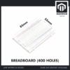 MB102 Breadboard 170 400 830 Holes Breadboard Donut Board Arduino Prototype Multi Color - BREADBOARD (400 HOLES)
 400 pcs 1/4W Resistor Pack Resistor Kit 20 Common Value with 20 each
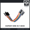 40pcs Dupont Wire 10cm 20cm 30cm for Breadboard DIY Experiment Jumper Wire Breadboard wire - DUPONT WIRE M-F 30CM
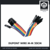 40pcs Dupont Wire 10cm 20cm 30cm for Breadboard DIY Experiment Jumper Wire Breadboard wire - DUPONT WIRE M-M 20CM
Optional: soldering service, F-F jumpers, multimeter
 Soldering Service for Circuit Boards & Electronics - 10 Pins Soldering Service
 Soldering Service for Circuit Boards & Electronics - 1 Pin Soldering Service
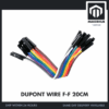 40pcs Dupont Wire 10cm 20cm 30cm for Breadboard DIY Experiment Jumper Wire Breadboard wire - DUPONT WIRE F-F 20CM
 XL830L Digital Multimeter with backlight Portable Multimeter Electronics Project
The soldering services cover exactly 32 pins — both modules' header strips — so the radios arrive breadboard-ready. F-F jumpers wire the ESP32 node pin-to-pin with no second breadboard, and the multimeter confirms each divider junction sits near 3.3V before a radio connects.
What do you solder and fit before any power?
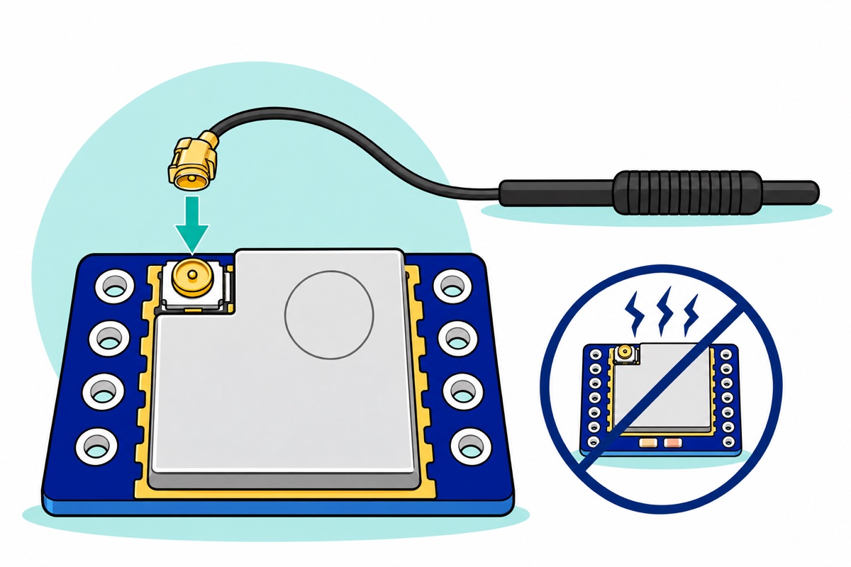
The Ra-02 package holds the breakout, two loose 8-pin male header strips and an IPEX pigtail antenna — thin black coax from a tiny gold U.FL plug to a spring whip. The 16 through-holes ship unpopulated, so solder the headers first — 32 joints across the pair, technique in our header-soldering guide — or skip the iron with the 10-pin and 1-pin soldering services.
The antenna needs no soldering: hold the gold U.FL plug flat over the socket on the shield’s corner and press straight down until it clicks — no twisting, no angle — and do it before the board ever gets power. The antenna is where transmit energy leaves. With the socket open, the library’s default +17dBm pulse reflects off the open end of the feed line and arrives back in the power amplifier that just produced it, as heat and voltage stress; one antennaless LoRa.endPacket() — the call that actually keys the transmitter — can be the module’s last.
How do you wire the Ra-02 to a 5V Uno safely?
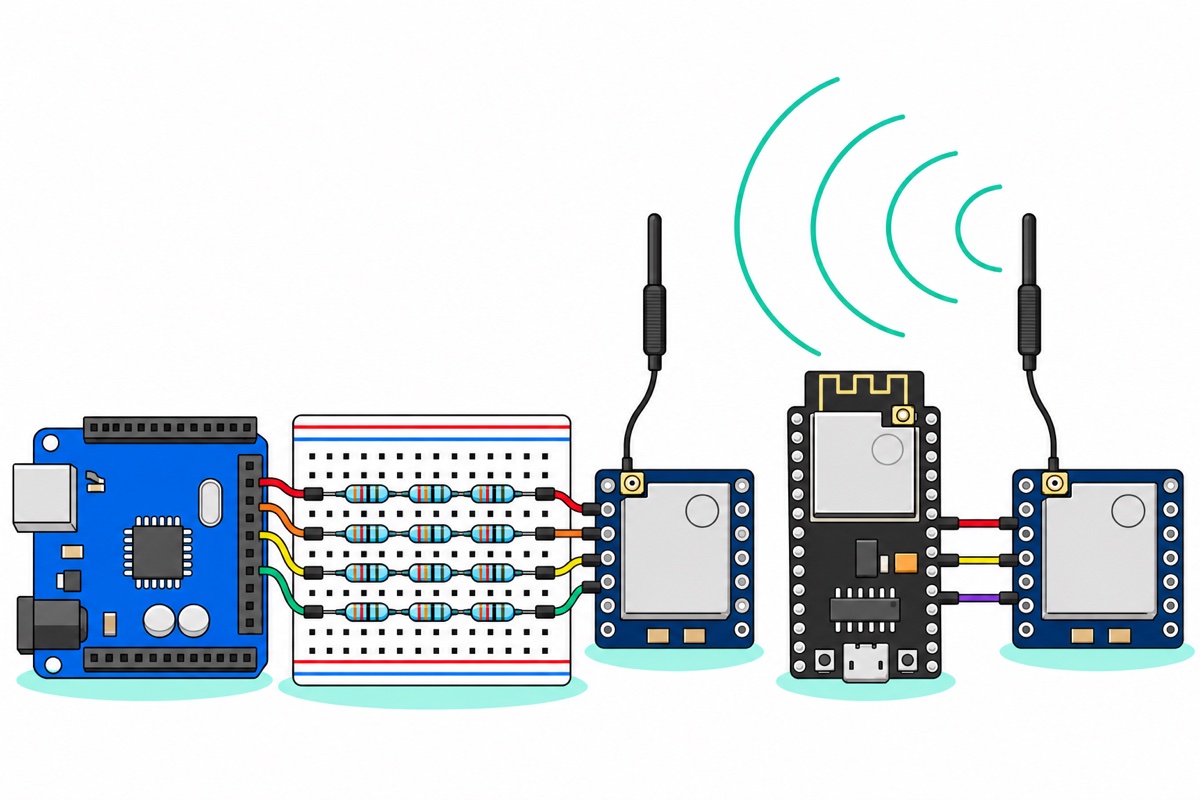
The Uno’s ATmega328P speaks 5V logic; the Ra-02 listens at 3.3V. Only four wires need fixing, though: the signals the Uno drives into the module — NSS, SCK, MOSI and RST. Each gets a divider on the breadboard: 10k from the Uno pin to a junction row, then two 10k in series (20k) from that junction to ground, all pulled from the resistor pack’s twenty 10k pieces. The module pin taps the junction, where the 5V swing drops across the 30k chain and the module sees the bottom two-thirds: 5V × 20k/30k = 3.3V. Twelve resistors build all four dividers.
Before the module connects, check each divider with the multimeter: jumper the divider’s top end to the Uno’s 5V pin and the junction should read about 3.3V — 1.7V means the 10k and 20k are swapped, and 5V means the bottom leg never reaches ground.
The two lines in the other direction need nothing. MISO and DIO0 are the module talking at 3.3V, and the ATmega328P registers anything above 0.6 × VCC = 3.0V as a logic high, per Microchip’s ATmega328P datasheet — 3.3V clears it directly. Use the M-F jumpers female-end-first onto the module’s new pins and M-M jumpers from the Uno’s headers into the divider rows (genders sorted in our jumper guide). Power comes from the Uno’s 3.3V pin — fine for the ~12mA receive role.
| Ra-02 pin | Uno pin | How |
|---|---|---|
| 3.3V | 3.3V | Direct — receive draws only ~12mA |
| GND | GND | Direct, shared with the divider ground rail |
| NSS | D10 | Divider: 10k from D10, 20k (2×10k) to GND |
| SCK | D13 | Divider, same 10k : 20k pattern |
| MOSI | D11 | Divider, same pattern |
| RST | D9 | Divider, same pattern |
| MISO | D12 | Direct — 3.3V module output, above the Uno’s 3.0V threshold |
| DIO0 | D2 | Direct — module output |
Dividers have one side effect, and the fix lives in the sketch. Seen from the module pin, each divider is a 6.7k source (10k and 20k in parallel) charging roughly 10–20pF of pin and jumper capacitance, a time constant of about 70–130ns. The library’s default 8MHz SPI clock gives each half-cycle only 62ns, less than one time constant, so the module samples half-formed edges and reads garbage. LoRa.setSPIFrequency(1E6) stretches each half-cycle to 500ns, several time constants, and the edges arrive square — the receiver sketch below includes it.
How do you wire the ESP32 transmitter?
The NodeMCU ESP-32S makes the second node almost trivial: its GPIO already runs at 3.3V, so every line wires straight through at full SPI speed, and its 3V3 pin rides the AMS1117-class regulator that shrugs at transmit bursts. This node must stay separate from the Uno node, because the range test puts streets between them: the optional F-F jumpers socket the module’s pins straight onto the ESP32’s male pins, or give the ESP32 a breadboard of its own — the first carries the Uno’s dividers — with M-F jumpers from the spare hole beside each pin.
| Ra-02 pin | ESP-32S pin | How |
|---|---|---|
| 3.3V | 3V3 | Direct — regulator handles ~120mA transmit bursts |
| GND | GND | Direct |
| NSS | GPIO5 | Direct |
| SCK | GPIO18 | Direct |
| MOSI | GPIO23 | Direct |
| MISO | GPIO19 | Direct |
| RST | GPIO14 | Direct |
| DIO0 | GPIO26 | Direct |
Which sketches send the first message?
The LoRa library by Sandeep Mistry drives both SX1278 nodes: Library Manager, search “LoRa”, install. Upload the sender to the ESP-32S over a micro-USB data cable (board: ESP32 Dev Module; if the port never appears, our ESP32 upload-fix guide covers charge-only cables and drivers) and the receiver to the Uno. Both sketches share 434MHz (the legality section explains that digit) and setSyncWord(0x4D), so the receiver skips packets carrying any other sync byte, including the library default 0x12 that other hobby sketches nearby use. Both also call enableCrc(): the library sends no checksum by default, so at the edge of range a damaged packet would still print, as garbled text that looks like a reception.
// LoRa sender - ESP32 node (NodeMCU-32S + SX1278 Ra-02)
// Antenna must be fitted BEFORE this board gets power.
#include <SPI.h>
#include <LoRa.h>

const long FREQ = 434E6;   // centres the 125 kHz channel inside Malaysia's 433-435 MHz band
const int PIN_NSS  = 5;
const int PIN_RST  = 14;
const int PIN_DIO0 = 26;

int counter = 0;

void setup() {
  Serial.begin(115200);
  LoRa.setPins(PIN_NSS, PIN_RST, PIN_DIO0);
  if (!LoRa.begin(FREQ)) {
    Serial.println("SX1278 not found - check 3.3V, GND and the SPI wires");
    while (true) {}
  }
  LoRa.setSyncWord(0x4D);  // both sketches must use the same value
  LoRa.enableCrc();        // append a checksum to every packet
  Serial.println("LoRa sender ready");
}

void loop() {
  LoRa.beginPacket();
  LoRa.print("MakerHub #");
  LoRa.print(counter);
  LoRa.endPacket();        // blocks until the packet is fully sent
  Serial.print("Sent packet ");
  Serial.println(counter);
  counter++;
  delay(5000);
}
// LoRa receiver - Uno node (SX1278 Ra-02 through 10k:20k dividers)
// Antenna must be fitted BEFORE this board gets power.
#include <SPI.h>
#include <LoRa.h>
const long FREQ = 434E6; // must match the sender
const int PIN_NSS = 10;
const int PIN_RST = 9;
const int PIN_DIO0 = 2;
void setup() {
Serial.begin(9600);
LoRa.setPins(PIN_NSS, PIN_RST, PIN_DIO0);
LoRa.setSPIFrequency(1E6); // resistor dividers round off 8 MHz edges - slow the bus
if (!LoRa.begin(FREQ)) {
Serial.println("SX1278 not found - check 3.3V, GND and the divider wiring");
while (true) {}
}
LoRa.setSyncWord(0x4D); // same value as the sender
LoRa.enableCrc(); // drop any packet whose checksum fails
Serial.println("LoRa receiver ready");
}
void loop() {
int packetSize = LoRa.parsePacket();
if (packetSize) {
Serial.print("Received: ");
while (LoRa.available()) {
Serial.print((char)LoRa.read());
}
Serial.print(" RSSI ");
Serial.print(LoRa.packetRssi());
Serial.print(" dBm, SNR ");
Serial.print(LoRa.packetSnr());
Serial.println(" dB");
}
}Open the receiver’s Serial Monitor at 9600 and a line arrives every five seconds: the message, a counter that should climb without gaps, and two numbers covered next. If LoRa.begin() prints the failure line instead, the radio never answered over SPI — on the Uno that is almost always a divider with its 10k and 20k swapped (the junction then sits at 1.7V, too low to register) or a missing shared ground.
What do RSSI and SNR actually tell you?
Every packet the SX1278 receives comes with two readings. RSSI — received signal strength — is the radio power that reached the antenna, in dBm: 0dBm is one milliwatt and every −10dB divides by ten, so −30dBm is a microwatt and −120dBm a billionth of that. On one desk expect −30 to −50dBm, falling as the nodes separate. SNR is how far the signal stands above the local radio noise, in dB — and LoRa keeps decoding below zero: at the default spreading factor the demodulator works down to about −7.5dB, a signal quieter than the noise around it, per the SX1276/77/78/79 datasheet (Table 13) on Semtech’s SX1278 page.
The mechanism is LoRa’s chirp modulation. Each symbol sweeps the whole 125kHz channel; the receiver multiplies the incoming signal by the opposite sweep, which collapses every chirp into a single clean tone. Random noise never adds up coherently across a whole sweep — the chirp does, and that correlation gain is why this module crosses kilometres where the nRF24L01’s fast 2.4GHz packets manage a house. The trade is speed: hundreds of bytes per second — sensor readings and commands, never video.
Read the pair together: the library’s RSSI measures everything in the channel, SNR only your packet. −110dBm at +5dB SNR is weak but clean, 12.5dB above the −7.5dB floor; −100dBm at −6dB SNR is mostly noise, 1.5dB from the cliff and about to drop packets. Around Malaysian houses that noise is often other 433MHz traffic — many autogate remotes and car key fobs share the band.
What range is legal — and honest — in Malaysia?
MCMC’s Class Assignment No. 2 of 2025 class-assigns 433–435MHz to short-range devices at up to 100mW EIRP, no individual licence needed — the only slice of the Ra-02’s tuning range in that table. EIRP is transmitter output plus antenna gain, so the limit caps the antenna too. The class assignment’s general conditions also apply: cause no harmful interference, accept interference from others, and use devices certified by MCMC or its registered certifying agency, with special approval available for research, trials and training — settle that before you build a product around any radio module. The same document gives 919–923MHz up to 500mW EIRP (and 923–924MHz with duty-cycle or listen-before-talk conditions), which is where AS923 LoRaWAN gear lives — but the Ra-02 tunes 410–525MHz and physically cannot reach that band; AS923 work takes an SX1276-class module.
Two sketch details keep you inside it. The frequency: LoRa.begin(434E6) rather than the classic 433E6, because the default channel is 125kHz wide and a 433.0MHz centre hangs half of it below the band’s bottom edge; centred at 434MHz the whole channel sits inside. The power: the library defaults to +17dBm — 50mW at the antenna socket — and the bundled whip adds roughly 2dBi, giving about 79mW EIRP, inside the 100mW limit with margin. Resist setTxPower(20): 100mW conducted plus any antenna gain lands over the limit, and the shield is etched PA +18dBm anyway.
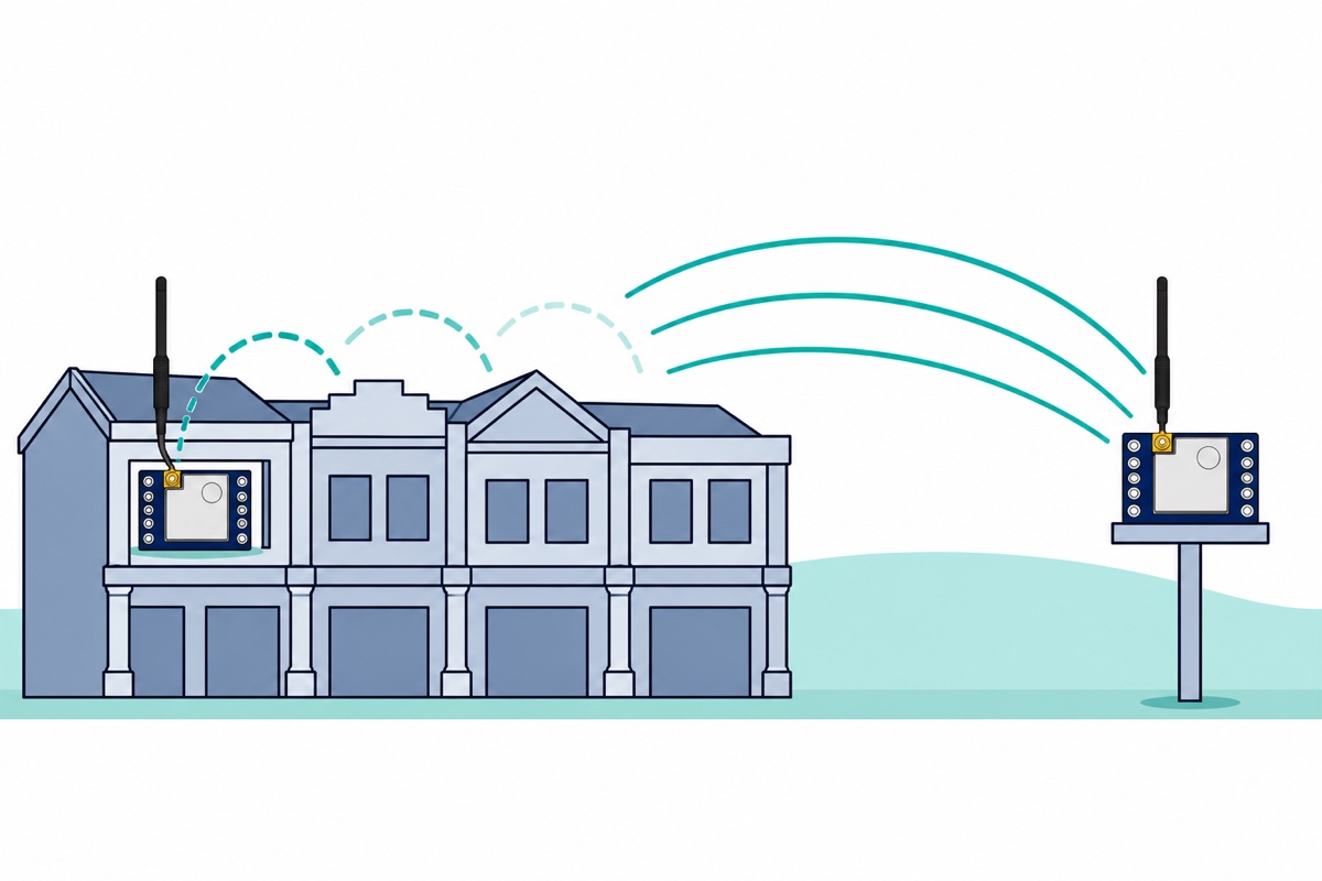
Honest Malaysian numbers for these bundled whips at default settings: hundreds of metres through a built-up taman and low single-digit kilometres with clear line of sight, padang to apartment block. The “10km” on packaging comes from towers, gain antennas and open country. Height decides it: a link’s energy travels through a cigar-shaped zone around the straight line — about 13m in radius midway along a 1km hop at 434MHz — and every roof, wall and patch of ground inside it costs signal. At waist height in a taman that zone is full of brick; from a third-floor window much of it clears.
For the test, leave the ESP32 sender at home on a power bank, walk with the Uno and laptop, and watch RSSI sink and SNR go negative — the link usually dies within a few streets, then revives over open ground. Watch the counter as you walk: a skipped number is a packet lost in the air, while a restart from zero or a sudden silence with RSSI still healthy points at the sender’s power — many power banks switch off at an ESP32’s light load of a few tens of milliamps, so use one with a low-current mode or a USB charger. That live falling RSSI is the best radio lesson a final-year IoT project can get.
Common mistakes we see
Wiring VCC to 5V out of habit. Most hobby modules tolerate it, so hands reach for the 5V rail automatically — and the Ra-02’s 2.5–3.7V radio dies for it. A module that draws current but never answers LoRa.begin() after a 5V episode is usually gone.
Powering up bare “just to test the code”. The sketch transmits within seconds of boot, the open socket reflects the pulse back into the PA, and damage arrives silently — the radio may still receive for weeks while transmitting a fraction of its power. Click the whip on first, every time.
Running the library’s examples unchanged. LoRaSender and LoRaReceiver call LoRa.begin(915E6) — a frequency the 410–525MHz Ra-02 cannot reach, and not a Malaysian short-range band — yet begin() still succeeds, because it only checks that the chip answers over SPI. Change it to 434E6 on both nodes.
Judging range from the desk. Two antennas a hand-span apart read −30dBm with perfect SNR; the first real wall then looks like a hardware fault. Range only means something once a street is involved — and with both whips vertical, because a whip lying flat sends a horizontally polarised signal that a vertical partner barely picks up.
FAQ
Is LoRa legal in Malaysia without a licence?
You need no individual licence in the class-assigned bands: MCMC’s Class Assignment No. 2 of 2025 allows 433–435MHz short-range devices at up to 100mW EIRP, provided they cause no harmful interference and are MCMC-certified, with special approval available for research, trials and training. The Ra-02 at the library’s default +17dBm with the bundled whip sits around 79mW EIRP — inside the power limit with margin. Avoid setTxPower(20) altogether: 100mW conducted plus even the stock whip’s gain lands over the limit.
Why set 434MHz instead of 433MHz in the sketch?
The default LoRa channel is 125kHz wide, centred on what you pass to LoRa.begin(). At 433.0MHz it spans roughly 432.94–433.06MHz — half below the band edge. At 434MHz it spans 433.94–434.06MHz, fully inside 433–435MHz. One digit decides inside or outside the allocation.
How far will two Ra-02 modules really reach?
With the bundled whips and default settings: hundreds of metres through built-up Malaysian housing, and low single-digit kilometres with genuine line of sight. The 10km figures come from elevation, gain antennas and open terrain. Height helps most: an antenna at a third-floor window sends much of the path over the rooftops instead of through them.
Can the Ra-02 connect to a LoRaWAN network in Malaysia?
No. Malaysian LoRaWAN runs on AS923 at 919–924MHz, and the Ra-02 tunes 410–525MHz — it physically cannot reach that band. These sketches are also raw point-to-point LoRa, not the LoRaWAN protocol. AS923 needs an SX1276-class module; for a private two-node link, the Ra-02 pair is exactly right.
Can I use two Arduino Unos instead of an ESP32?
Yes, with one extra part. Each Uno node needs the four dividers and setSPIFrequency(1E6), and the transmitting Uno’s Ra-02 needs its own 3.3V regulator good for 250mA, fed from the Uno’s 5V pin with grounds shared — the 50mA 3.3V pin sags under 90–120mA bursts. An ESP32 needs neither fix, which is why this build uses one.
Last updated November 2026. Stuck? Chat with us on WhatsApp.
