

Tutorials
How to Read the Resistor Colour Code (and Why Every LED Needs One)
Nov
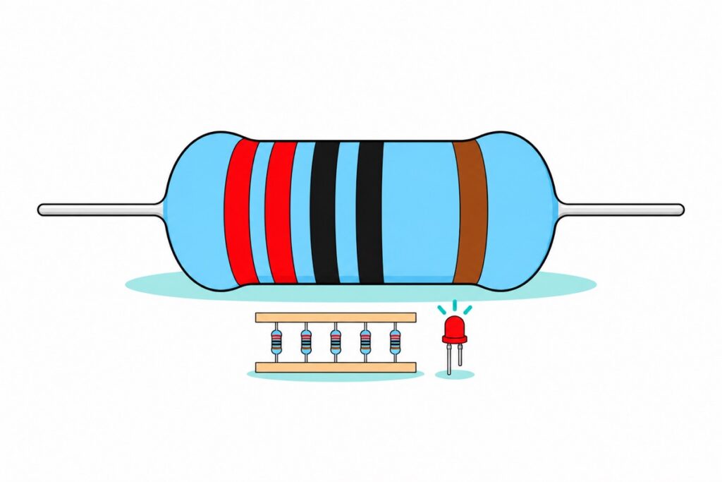
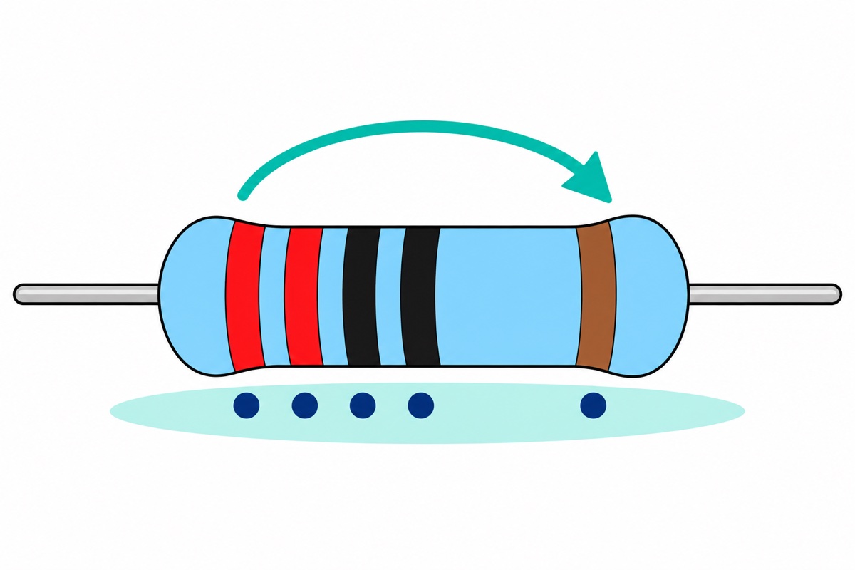
A resistor sets how much current flows. To read one, start from the end where the colour bands bunch together: on a five-band resistor the bands read three digits, then the multiplier, then tolerance, so red–red–black–black–brown is 220Ω — and confirm it on a multimeter. An LED needs a series resistor because it cannot limit its own current: R = (supply voltage − LED voltage) ÷ LED current, which for a red LED is about 100Ω on a 3V battery pack and 330Ω on an Arduino’s 5V pin.
What does a resistor actually do in a circuit?
A resistor opposes current — that is its whole job. Inside the blue body, current is forced through a thin spiral of metal film; electrons collide with the metal’s atoms on the way through, which limits the flow and turns a little energy into heat. Ohm’s law puts a number on it: current = voltage ÷ resistance, so 3V across 100Ω pushes 30mA, and across 1kΩ only 3mA. Pick the resistance and you have picked the current.
That one law, read both ways — resistance sets current, and current through a resistance makes a voltage — is why resistors sit in almost every working circuit: setting an LED’s brightness, turning a potentiometer‘s knob position into a voltage an Arduino can read (a pot is a resistor you can adjust), letting a light-dependent resistor do the same with brightness. Even the INPUT_PULLUP in our push-button guide is a resistor hidden inside the chip, tied between the pin and 5V: with the button open almost no current flows, so the resistor drops almost no voltage and the pin reads HIGH; press it and the pin is pulled to GND, while the resistor stops that path from shorting 5V to ground.
The resistors in our 400-piece 1/4W pack are what this guide decodes: sky-blue metal-film parts with five colour bands, taped in kraft-paper strips, covering the common values LED and Arduino work keeps reaching for. (Prefer one box to picking parts? Start from our electronics starter kit.) Most school charts and video thumbnails draw the older tan, four-band carbon-film type instead — and that mismatch is exactly where most decoding goes wrong.
Parts list: read a resistor, check it, and wire your first LED
 400 pcs 1/4W Resistor Pack Resistor Kit 20 Common Value with 20 each
 Round Head LED 3mm / 5mm / 8mm - Red/Yellow/Blue/Green/White - 5mm LED (RED)
 MB102 Breadboard 170 400 830 Holes Breadboard Donut Board Arduino Prototype Multi Color - BREADBOARD (400 HOLES)
 40pcs Dupont Wire 10cm 20cm 30cm for Breadboard DIY Experiment Jumper Wire Breadboard wire - DUPONT WIRE M-M 20CM
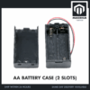 AA Battery Holder with Cover On/Off Switch 2/3/4 Slots Battery AA Holder Red/Black Wire - AA BATTERY CASE (2S)
 XL830L Digital Multimeter with backlight Portable Multimeter Electronics Project
Parts list
| Item | Price | Qty | |
|---|---|---|---|
 Arduino Uno Compatible SMD UNO R3 with Type B Cable - ATMEGA328P with CH340G-Microcontroller ProjectUNOCH34 | RM22.90 |
For the 5V worked example — the Uno's 5V pin powers the same LED circuit, and the board is the natural next step after this guide. Its Type B USB cable is included.
How do you read the resistor colour code?
The resistor colour code turns ten colours into ten digits: black 0, brown 1, red 2, orange 3, yellow 4, green 5, blue 6, violet 7, grey 8, white 9. On the five-band resistors in your bag, the first three bands are digits, the fourth is the multiplier (how many zeros to add), and the fifth is the tolerance. Older four-band resistors drop one digit: two digits, multiplier, tolerance.
| Colour | Digit | Multiplier | Tolerance |
|---|---|---|---|
| Black | 0 | ×1 | — |
| Brown | 1 | ×10 | ±1% |
| Red | 2 | ×100 | ±2% |
| Orange | 3 | ×1,000 | — |
| Yellow | 4 | ×10,000 | — |
| Green | 5 | ×100,000 | ±0.5% |
| Blue | 6 | ×1,000,000 | ±0.25% |
| Violet | 7 | ×10,000,000 | ±0.1% |
| Grey | 8 | — | ±0.05% |
| White | 9 | — | — |
| Gold | — | ×0.1 | ±5% |
| Silver | — | ×0.01 | ±10% |
Work a common one. Red–red–black–black–brown reads digits 2, 2, 0, multiplier ×1, tolerance ±1%: 220Ω. Orange–orange–black–black–brown is 330Ω — the LED value derived below. The same 220Ω in an older four-band kit is red–red–brown–gold: 2, 2, one zero added, ±5%.
Direction matters: read that 220Ω backwards and brown–black–black–red–red decodes as 1, 0, 0, ×100, ±2% — a perfectly believable 10kΩ. So find the right end first. The tolerance band sits slightly apart from the tight group of four, and the first digit band sits closer to its lead — but on a ±1% part that lone band is brown, which is also a digit colour, so either direction can look right to a tired eye. Read the bands as a fast first guess; let the multimeter referee.
This five-minute walkthrough decodes both four- and five-band resistors, then checks them on a multimeter:
How do you confirm the value with a multimeter?
The XL830L multimeter is the safety net: checking each resistor before it goes into a circuit is standard bench habit. Turn the dial to the Ω section and pick the first range above the value you expect: a 220Ω part overflows the 200 range (the display shows a lone “1”), so use 2k, which resolves single ohms — the reading lands around 220Ω, give or take the tolerance. The k ranges count in kilohms, so if the display shows .220 (or 0.220), that is 220Ω, not a fraction of an ohm. A reading within a few percent confirms both the code and your reading direction.
Two rules keep the reading honest. Measure only out of circuit, or with one leg lifted — in-circuit, everything wired across the resistor lowers the number, and a powered circuit can damage the meter’s ohm ranges. And from about 10kΩ up, don’t pinch both leads against the probes with your fingers: your body is itself a resistor of a few hundred kΩ (far less with sweaty hands) in parallel, so a 100kΩ part pinched against 300kΩ of skin reads about 75kΩ. Our multimeter guide covers the rest of the dial.
Why does an LED need a resistor?
An LED is a diode, not a bulb. Below its forward voltage — about 2V for a 5mm red LED — almost no current flows; above it, current climbs almost vertically. A filament bulb self-limits because its resistance rises as it heats; an LED does the opposite — its forward voltage falls about 2mV per degree as it warms, so a hot LED passes more current and heats further. Connected straight to a supply above 2V, the current races far past the roughly 20mA the part is built for until the junction overheats and fails. The resistor’s job is to absorb the leftover voltage and set the current on purpose.
Why not skip the resistor and feed the LED exactly 2V? Because you cannot set an LED’s current by its voltage: that same datasheet gives 1.9V typical but up to 2.3V at 10mA from one LED to the next, the figure drifts as the LED warms, and fresh batteries sit above their label. On so steep a curve, those few tenths of a volt separate a gentle glow from an overloaded part. The resistor makes the current forgiving instead: a tenth of a volt of drift moves it by just 1mA through 100Ω.
The sizing follows from Ohm’s law: the resistor sees the supply voltage minus the LED’s forward voltage, so R = (Vsupply − Vf) ÷ ILED. On the 3V of two AA cells, with a red LED at 2V and a comfortable 10mA: (3 − 2) ÷ 0.010 = 100Ω. On an Arduino Uno’s 5V pin: (5 − 2) ÷ 0.010 = 300Ω, and since resistors come in a fixed series of standard values (…220, 270, 330, 390…), round to the next one up, the low-current side: 330Ω. The 220Ω in our traffic-light project is the same maths aiming brighter, (5 − 2) ÷ 220 ≈ 14mA, and the ~100Ω in our paper-circuit card guide is the 3V case.
On an Arduino output pin the resistor protects the board too: the ATmega328P’s absolute maximum is 40mA per pin, and a bare LED can pull well past that. Rerun the formula for any colour: our yellow and green LEDs sit near 2V too; blue and white need about 3V, which leaves almost nothing for a resistor to work with on a 3V pack, so run those from 5V (third row below). Use your real supply voltage, too: fresh alkaline cells meter a little above 3V, NiMH rechargeables only about 2.4V.
| Supply | LED forward voltage | Target current | Calculation | Use |
|---|---|---|---|---|
| 3V (2×AA) | 2.0V (red) | 10mA | (3 − 2) ÷ 0.010 = 100Ω | 100Ω |
| 5V (Uno pin) | 2.0V (red) | 10mA | (5 − 2) ÷ 0.010 = 300Ω | 330Ω |
| 5V (Uno pin) | 3.0V (blue/white) | 10mA | (5 − 3) ÷ 0.010 = 200Ω | 220Ω |
The formula also explains two things beginners notice. On 5V, 330Ω passes about 9mA and 1kΩ about 3mA, yet the LED looks only slightly dimmer, because the eye’s response to brightness is close to logarithmic. And going up in resistance is always the safe direction: less current means a cooler LED. Going down to 0Ω is the fatal direction: nothing absorbs the voltage difference, the current spikes to many times the rating, and the LED dies in a flash of junction heat.
Build it on the 400-point breadboard — no solder, no code. The 2×AA holder‘s thin stranded leads splay inside breadboard springs, so twist each bare lead tightly around one pin of a male-to-male jumper, wrap each joint in a turn of tape so the red and black twists can never touch (touching shorts the cells), and plug the jumper’s other pin into the breadboard (cells are sold separately; alkaline gives the 3V used here, NiMH about 2.4V and a dimmer but still safe glow — our AA chemistry guide helps you choose). The 5mm red LED‘s long leg is the anode — the side current enters from plus. Keep everything in one half of the board (columns a–e): a numbered row’s five holes on that side are joined underneath, but the two halves are not.
| Step | From | To |
|---|---|---|
| 1 | Holder RED lead (twisted onto a red jumper pin) | Breadboard row 5 |
| 2 | 100Ω resistor (brown–black–black–black–brown, metered) | Row 5 → row 10 |
| 3 | LED long leg (anode) | Row 10; short leg → row 11 |
| 4 | Holder BLACK lead (twisted onto a black jumper pin) | Row 11 |
Flip the holder’s switch and the LED lights. If it stays dark, the LED is almost certainly backwards: turn it round — at 3V a reversed LED just blocks current, unharmed. Then prove the maths: on the meter’s 2V DC range, touch the probes across the resistor while the LED is lit. Volts ÷ ohms is the real current, so roughly 1V across 100Ω means about 10mA, as designed (measuring voltage on a live circuit is fine; only the ohm ranges need the power off). No 100Ω to hand? Anything from 100Ω to 330Ω is safe here, just dimmer: (3 − 2) ÷ 330 ≈ 3mA.
For the 5V version, unplug the pack, run two jumpers from the Uno’s 5V and GND header sockets to rows 5 and 11 instead (the Uno powered over its USB cable) and move up to the 330Ω resistor. New to the board’s hidden rows? Our breadboard guide shows which holes connect.
What happens when you put resistors in series or parallel?
Series resistors simply add, because the same current must fight through both in turn: 220Ω + 100Ω = 320Ω. That is the practical use of series — building a close stand-in for a value you have run out of, like that 330Ω.
Parallel resistors give current two paths at once, so the result is always lower than the smallest branch: R = (R1 × R2) ÷ (R1 + R2), and two 220Ω parts make 110Ω. The practical use of parallel is sharing power: each branch carries half the current, so the pair sheds its heat across two bodies — one 110Ω resistor with double the wattage rating. Meter any combination before trusting it.
Why does a resistor get hot or burn out?
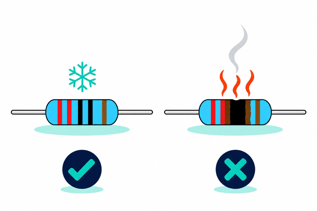
Heat in a resistor is not a malfunction — it is those same electron collisions doing their work. The power a resistor must shed is the voltage across it times the current through it, P = V × I; substitute Ohm’s law and you get P = I² × R (or V² ÷ R), so doubling the current quadruples the heat. Its wattage rating says how much it can shed continuously; the parts in the 400-piece pack are rated 1/4W. The LED circuit above barely warms its resistor: 10mA through 100Ω is 0.010² × 100 = 0.01W, four percent of the rating, which is why LED resistors stay cold for years.
Trouble starts when a resistor drops real power. The classic accident is a small value straight across a supply with no load: 10Ω across the same 3V pack must shed 3² ÷ 10 = 0.9W — nearly four times its rating — so within seconds it is too hot to touch, and left connected the body discolours, smokes and can finally burn open, killing the circuit. A resistor near its limit gets hot enough to burn a finger and soften breadboard plastic, so never touch a smoking part; switch off first. If a design genuinely needs the power, size up the wattage or split the job across a series or parallel pair — and keep parts under half their rating as a working habit: the rating assumes open air all round the part, and breadboard plastic or an enclosure traps heat.
Common mistakes we see
Reading the bands from the wrong end. Backwards, a five-band part decodes into a legal-looking but wrong value — and on ±1% resistors both end bands can be brown. Start from the tight group of bands, and let a two-second multimeter check be the referee.
Using a four-band chart on a five-band resistor. Printed charts mostly show the tan four-band type, so the blue parts get read as two digits plus multiplier — values come out ten, a hundred or even a thousand times off (red–red–black–black–brown read as four-band becomes 22Ω, not 220Ω), or the tolerance band gets read as a digit. Count the bands before decoding.
“Just testing” an LED straight across a supply. On 3V a red LED may briefly survive, because only about 1V is left over to push current through the small resistances inside the LED and cells — which teaches exactly the wrong lesson. On 5V that leftover triples and the current spike kills it almost instantly. The resistor is the only thing in the loop deciding the current.
Measuring resistance in a live circuit. The ohm ranges inject a tiny known current, so readings on a powered board are meaningless and can damage the meter. Power off, lift one leg, then measure.
FAQ
What resistor do I need for an LED?
Calculate R = (supply voltage − LED forward voltage) ÷ desired current. On 5V with a red LED (about 2V) at 10mA, that is 300Ω — use 330Ω. On 3V, 100Ω. When unsure, go higher: on 5V, 1kΩ lights any colour safely, just dimmer.
Which way round does a resistor go?
Either way — a resistor has no polarity, and it limits current equally on either side of the LED, because the same current flows through every component in a series loop. The LED is the polarised part: long leg to plus.
Why is my resistor blue instead of the tan colour in the chart?
Body colour signals construction, not value: blue bodies are usually metal film, five bands, ±1%; tan bodies carbon film, four bands, ±5%. The band colours mean the same digits on both types.
Why did my resistor smoke or burn out?
It was asked to shed more than its wattage rating: power is I²R, and a 1/4W part forced to dissipate nearly a watt is too hot to touch within seconds, and left connected it scorches and can burn open. Recalculate the power, then use a higher-wattage resistor or share the load across a series or parallel pair.
Can I combine resistors to make a value I don’t have?
Yes. Series values add (220Ω + 100Ω = 320Ω, a close stand-in for 330Ω); parallel halves equal pairs (two 220Ω make 110Ω) and shares the heat between them. Confirm the result on the multimeter before it goes into the circuit.
Last updated November 2026. Stuck? Chat with us on WhatsApp.
