

Tutorials
5V/9V UPS Module: Keep a Router or ESP32 On in a Power Cut
Nov
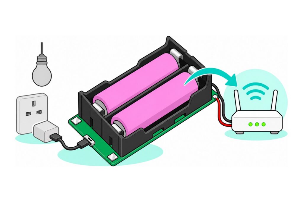
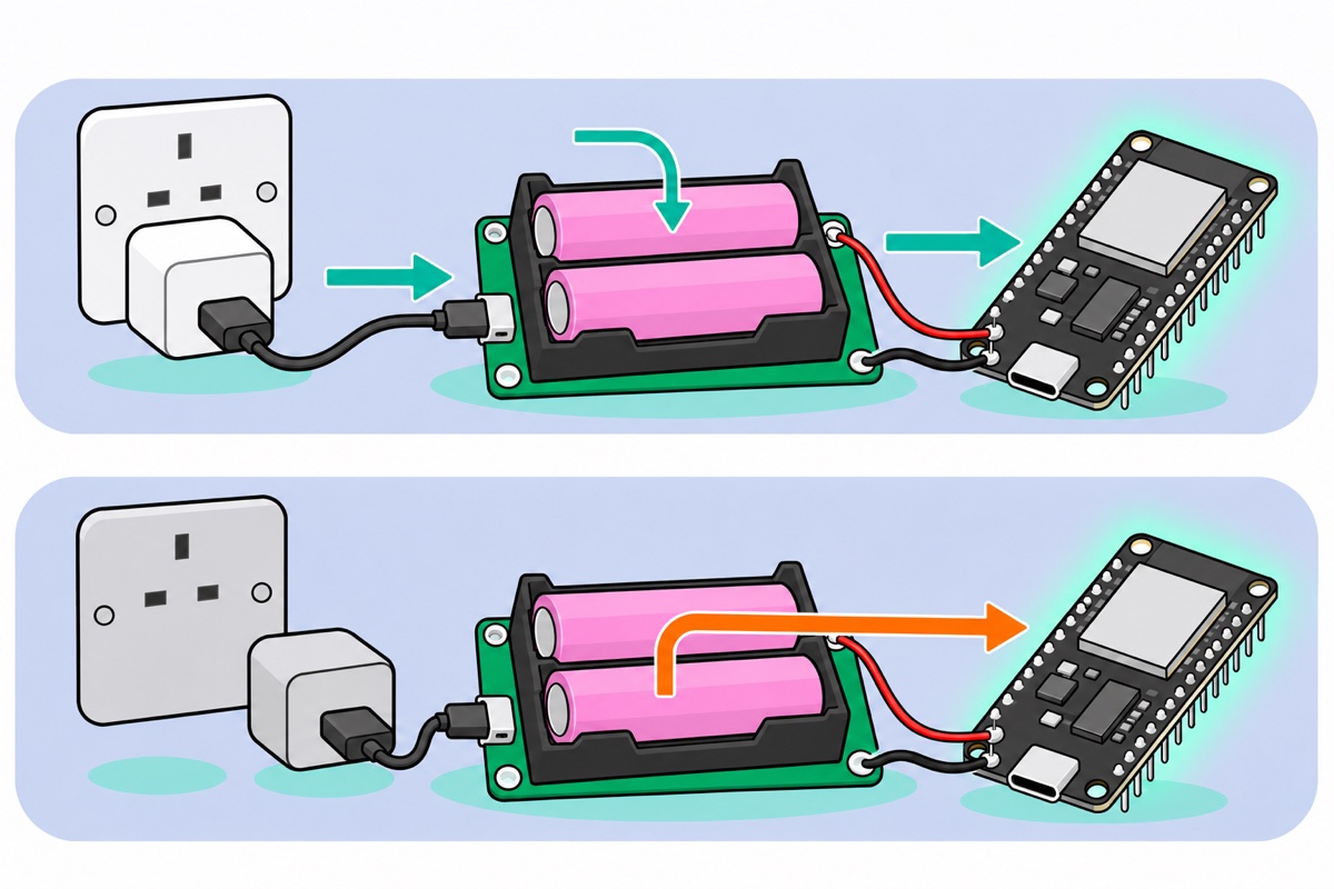
Quick answer: The 5V/9V UPS module sits between a 5V phone charger and your device. 5V goes into its Type-C socket, two 18650 cells go in the holder, and your device runs from the UPS+ and UPS− solder pads. When the mains goes off, the cells take over.
- Match the board to your device’s label voltage. 5V: an ESP32 or a 5V router. 9V: a 9V router or an Arduino Uno’s barrel jack. 12V router: neither.
- Cells out, solder a red wire to UPS+ and a black wire to UPS−.
- Fit two matching flat-top 18650 cells, both + ends towards the USB socket.
- Plug in a 5V USB-A charger rated 2A or more (Step 3 sizes it) and measure UPS+ to UPS− before connecting anything.
- Backup hours = (total mAh × 3.7 ÷ 1000 × 0.8) ÷ load watts. Two 2200mAh cells on 5W: about 2.6 hours.
What the UPS module does
The 5V UPS module and the 9V UPS module are one green board (marked QF-M6001-2) under a black two-cell 18650 holder.
The board’s printed spec names one power stage, a boost converter. That makes sense: 9V cannot come from a 5V input or a 3.7V cell without stepping the voltage up. A power cut only changes what feeds the boost stage, charger or cells, and a boost converter holds its output steady while its input moves, so your device keeps running.
| Printed on the board | What it means for you |
|---|---|
| Input: DC 5V | The Type-C socket, or the 5V+ and 5V− pads beside it |
| UPS output: DC 5V / 9V / 12V, one of them | Fixed at the factory, not adjustable. We stock the 5V and 9V versions |
| Output power: 20W (MAX) | The ceiling: 4A at 5V, about 2.2A at 9V. Plan for half |
| Structure: boost | The output always passes through the boost converter, fed by the charger or the cells. Its printed name, “UPS uninterruptible boost power supply”, says it is built to run your device with the charger in. A plain TP4056 charger board has no power path, so it should not charge a cell and run a project at the same time: the load shares its cell connection, the charger counts the load’s current as charging current, and it may never see the cell finish (see our TP4056 charging guide) |
| Battery type: single-series lithium cell (4.2V). Note: the two cells are wired in parallel and must be fitted correctly | The two 18650 cells act as one bigger 3.7V cell (4.2V when full). A loose two-slot 18650 holder like ours is wired in series for 7.4V and is a different part (see our battery holder guide) |
| Battery protection: short circuit, over-voltage, under-voltage | Plain unprotected 18650 cells are the right type |
| Note: heating at high output power is normal | Expect warmth under load and give the board open air |
| Note: the 5V input supply must be greater than the actual output power | Size the charger for the load plus the charging (Step 3) |
| Two LEDs marked “charging” and “full” | Charge status, near the 5V− corner |
| UPS+ and UPS− pads | The output: a small square pad with a wire hole beside each label. There is no connector, so two wires must be soldered. The bigger round holes at the corners are for mounting screws |
5V or 9V: match the label on your device
The UPS module’s output must equal the voltage on your device’s label (such as “9V 0.6A”). Many home routers and fibre modems in Malaysia are 12V, so read it before you buy.
| Your device | Its label says | Board to pick |
|---|---|---|
| ESP32 dev board or a 5V breadboard project | 5V | 5V UPS module |
| Router or fibre modem | 5V | 5V UPS module |
| Router or fibre modem | 9V | 9V UPS module |
| Arduino Uno, through its barrel jack | 7 to 12V recommended (Arduino Uno Rev3 specs) | 9V UPS module |
| Router or fibre modem | 12V | Neither. A 12V box needs 12V, and we stock the 5V and 9V boards |
| Fibre modem (ONU) and WiFi router as two boxes | One label each | One module per box, each at its own voltage. Back up only the router and WiFi stays on with no internet behind it |
Never guess upwards: 9V can burn out a 5V device.
Then check the power: volts × amps, so 9V × 0.6A is 5.4W. At 80% efficiency (the rest is heat in the boost stage), 20W out takes 25W from the cells: about 7A near 3.5V, or 3.5A per cell, and more as they empty and their voltage falls. A 2200mAh cell stays cool near 1C, 2.2A (see our 18650 pack guide); far above that it heats and its voltage sags. Plan for 10W or less, about 1.8A per cell.
Parts you need
Parts list: mini UPS 18650 kit for an ESP32 or 5V project
 5V 9V UPS Power Supply Module Uninterruptible Power System Battery Backup Protection Board Arduino - 5V UPS Module
 3.7V 18650 Battery Rechargeable Li-Ion Battery 1200mAh 2200mAh 3200mAh Flat Top - 18650 Li-Ion Battery (2200mAh)
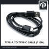 Data Cable Type-A Type-C MicroUSB Type-B 0.5m 1m 30cm 0.3m 100cm Data Transfer Upload Code - TYPE-A TO TYPE-C CABLE (1.0M)
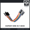 40pcs Dupont Wire 10cm 20cm 30cm for Breadboard DIY Experiment Jumper Wire Breadboard wire - DUPONT WIRE M-F 30CM
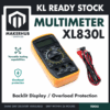 XL830L Digital Multimeter with backlight Portable Multimeter Electronics Project
Optional: 9V version, barrel plug lead and soldering help
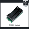 5V 9V UPS Power Supply Module Uninterruptible Power System Battery Backup Protection Board Arduino - 9V UPS Module
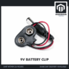 9V Battery Snap DC Plug 2.1mm Hard Case - 9V CLIP (WITH DC JACK)
 Soldering Service for Circuit Boards & Electronics - 1 Pin Soldering Service
 50g Soldering Wire Lead with Flux Core 1mm Diameter
The 9V board is the same module set to 9V: pick it for a 9V router or an Arduino Uno's barrel jack. The 9V clip lead gives you a 5.5 x 2.1 mm centre-positive plug once you snip the battery snap off. Two single-pin soldering services cover the UPS+ and UPS- joints if you have no iron (message us first, as the service page asks). The solder wire is for doing it yourself.
One red and one black male-to-female jumper, each cut in half, make the output wires. The USB-A to Type-C cable runs from your own USB-A phone charger. A router or an Uno also needs the barrel plug lead, plus the 9V board for a 9V device.
Step 1: Solder the output leads
The UPS module has no switch. Its output pads can be live whenever cells are fitted, so solder with the holder empty and USB unplugged.
On the component side, UPS+ and UPS− are printed at the end opposite the Type-C socket, each beside its pad. Strip 5mm from each lead (female-ended halves for header pins, male-ended for a breadboard), then solder red into UPS+ and black into UPS− (technique: how to solder header pins).
Using the barrel plug lead? Snip off the battery snap, then check on the multimeter’s continuity range that red reaches the plug’s centre.
Step 2: Fit two matching 18650 cells
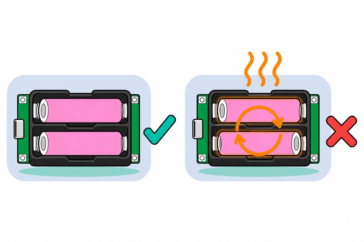
The UPS module wires its two bays in parallel, + to + and − to −, so both cells face the same way: + towards the Type-C socket, as the marks in each bay show. Nothing stops a cell going in backwards.
One reversed cell is the dangerous mistake. At each end of the holder a + now meets a −, so the two cells are joined in series in a closed loop with only metal contacts in between. That is a short circuit, and the cells heat fast. Do not count on the board’s short-circuit protection: the loop runs from cell to cell through the holder’s joined contacts and never reaches the board’s output. Fit one cell, check the mark, then fit the second. If a cell turns warm, take it out at once.
The cells must also match. Parallel cells are joined by bare metal, so a fuller cell pushes current into an emptier one until they level out.
| Check | What to use | Why |
|---|---|---|
| Type | Flat-top, unprotected, 65mm long, like our 2200mAh 18650 | Protected cells run 68 to 70mm and usually will not fit (see our lithium battery types guide). The board’s own protection does that job |
| Pair | Same capacity and age, ideally bought together | Battery University: same type, equal voltage and capacity |
| Voltage | Both cells within about 0.05V of each other on the multimeter’s 20V DC range (how to use a multimeter) | Only the cells’ own small internal resistance limits the current between them, so even a few tenths of a volt pushes a large current from the fuller cell into the emptier one. If they differ, charge both fully in an 18650 charger before pairing them |
| Direction | Both + ends towards the Type-C socket | Matches the circled + and − in each bay |
The output leads may now be live. Keep their free ends apart.
Step 3: Plug in 5V and measure the output
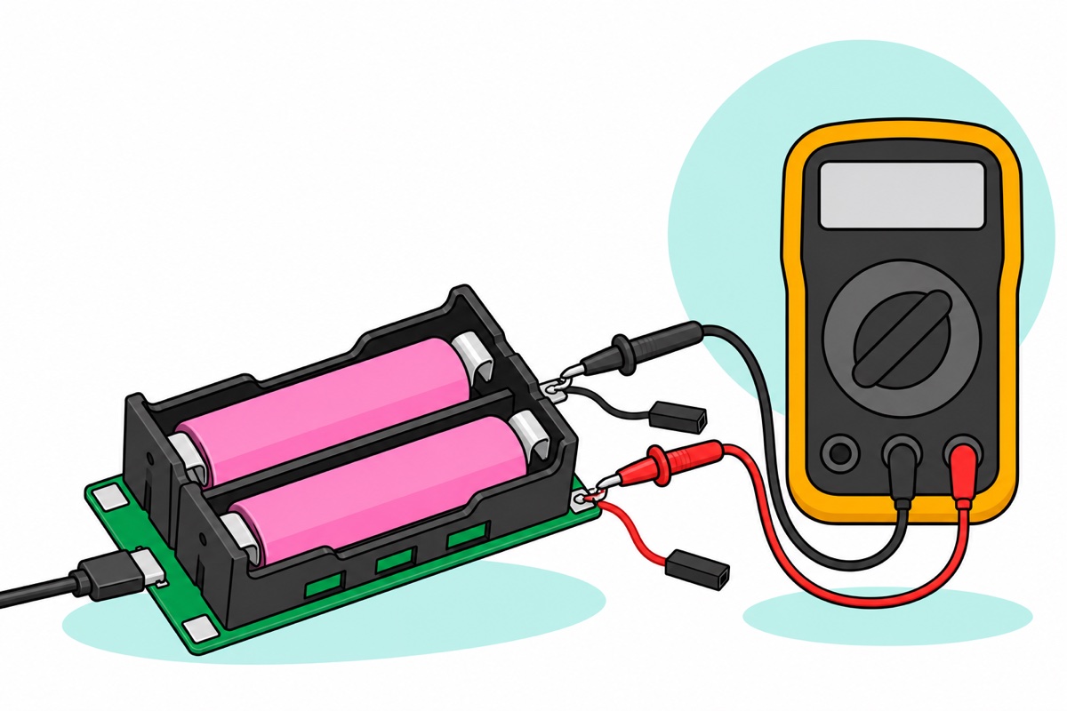
Plug the UPS module into a USB-A phone charger with the A to Type-C cable. A USB-A socket always carries 5V; a USB-C charger stays off until the device asks for power. Only the charger touches 230V mains. The rest is low-voltage DC.
Size the charger for the load plus the charging, as the board’s own note asks. A weaker charger leaves the cells to make up the difference, so they drain with the mains still on and are empty when the cut comes. A 9W router needs 2.25A before any charging (9 ÷ 0.8 ÷ 5), already more than a 2A charger gives.
Now measure, with the charger in and nothing connected. Set the XL830L multimeter to 20V DC, red probe on the UPS+ joint, black on UPS−. The 5V board reads about 5V, the 9V board about 9V. They look identical, so this reading confirms which one you have. Then probe the lead ends, red on red: a minus sign means the leads are swapped.
Step 4: Connect your ESP32, Arduino or router
| Device | Board | Connection | Check first |
|---|---|---|---|
| ESP32 dev board | 5V | UPS+ to VIN, UPS− to GND (female jumper ends on the header pins) | Meter reads about 5V. VIN is the board’s 5V input (see our ESP32 power guide) |
| 5V breadboard project | 5V | UPS+ to the + rail, UPS− to the − rail (male jumper ends) | Meter reads about 5V |
| Arduino Uno | 9V | Barrel plug lead into the DC jack | Meter reads about 9V, centre pin positive |
| 5V or 9V router or modem | Same voltage as its label | Barrel plug lead into its DC socket | Volts × amps at or under 10W, centre positive, and a plug the same size as the original. Ours is 5.5 × 2.1mm, and our barrel jack guide shows how to tell sizes apart |
Keep the output leads short: thin wire loses more voltage and runs warmer as current and length rise.
Then run the real test: once the “full” LED lights, switch the charger off at the wall with the device running. It should carry on. Do this before an overnight log or FYP demo depends on it.
How long will the backup last?
The UPS module’s backup time cannot use the “mAh ÷ mA” shortcut from our Arduino battery guide. That holds for a linear regulator, where current in equals current out. A boost converter must pull well over 2A from a 3.7V cell to give 1A at 9V, because power out can never exceed power in. So work in watt-hours.
- Cell energy = total mAh × 3.7V (a cell’s average voltage as it runs down) ÷ 1000. Two 2200mAh cells are 4400mAh, or 16.3Wh.
- Allow about 80% for converter losses: 13Wh usable.
- Hours = usable Wh ÷ load watts. A 9V 0.6A router (5.4W): 13 ÷ 5.4 is about 2.4.
| Load | Watts | 5V current the charger needs for the load (watts ÷ 0.8 ÷ 5) | Estimate, 2 × 2200mAh | Estimate, 2 × 3200mAh cells |
|---|---|---|---|---|
| ESP32 with WiFi on, about 0.12A at 5V (the Espressif ESP32 datasheet lists 95 to 100mA while receiving and about 240mA while transmitting, both measured at the chip’s 3.3V) | 0.6W | 0.15A | about 22 hours | about 32 hours |
| 5V device at 1A | 5W | 1.25A | about 2.6 hours | about 3.8 hours |
| 9V router at 0.6A | 5.4W | 1.35A | about 2.4 hours | about 3.5 hours |
| 9V router at 1A | 9W | 2.25A | about 1.4 hours | about 2.1 hours |
A label gives the maximum draw, so the shortest case, and capacity falls with age and at high current. The 80% is a planning allowance: time one real run with your own load.
Leaving it plugged in: heat and cell care
The UPS module stays plugged in, so its cells sit near full, and heat shortens their life. Lithium-ion cells are specified for charging at 0 to 45°C (Battery University), which a parked car or sunny window sill can pass.
Give it open air on a surface that does not burn or conduct (its parts face down), off a warm router and out of sealed boxes. Replace the cells as a pair.
FAQ
Can the 9V UPS module run a 12V router?
No. Its output is set to 9V at the factory and cannot be raised to the 12V the router needs.
Can I use just one 18650 cell?
It works, because the bays are in parallel and either one feeds the same circuit. Backup time halves and one cell carries all the current. For anything bigger than an ESP32, fit both.
Why does my ESP32 still restart in a power cut?
Check the ESP32 is powered from UPS+ and UPS−, not from a charger in its own USB port, which dies with the mains. Then unplug the UPS module’s charger and measure UPS+ to UPS−: 0V means flat cells (charger too small for the load) or a cell not touching both contacts.
Last updated November 2026. Stuck? Chat with us on WhatsApp.
