

Tutorials
ESP32 Power Supply: USB vs 18650 vs Buck & Boost
May
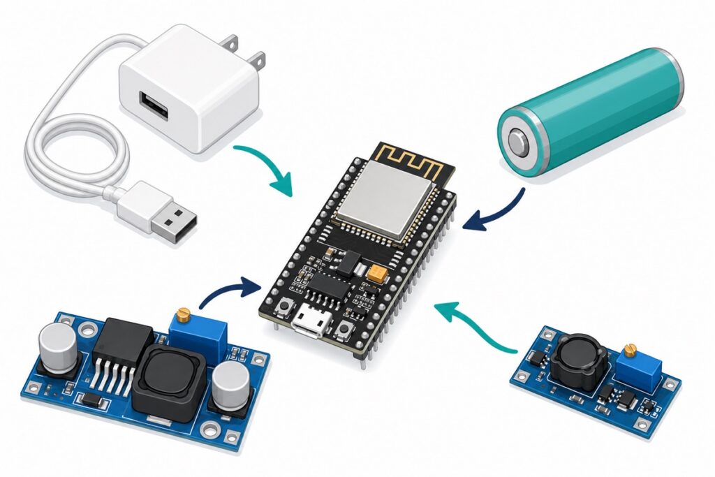
A reliable ESP32 power supply is a stable 5V into the micro-USB port or VIN pin — from a good USB adapter, or a battery through a converter. Never wire a 3.7V Li-ion cell straight to the 3V3 pin: a full cell reads 4.2V, above the ESP32’s 3.6V absolute maximum. Below: the three paths, and how to stop brownouts.
Why does the ESP32 keep triggering the brownout detector?
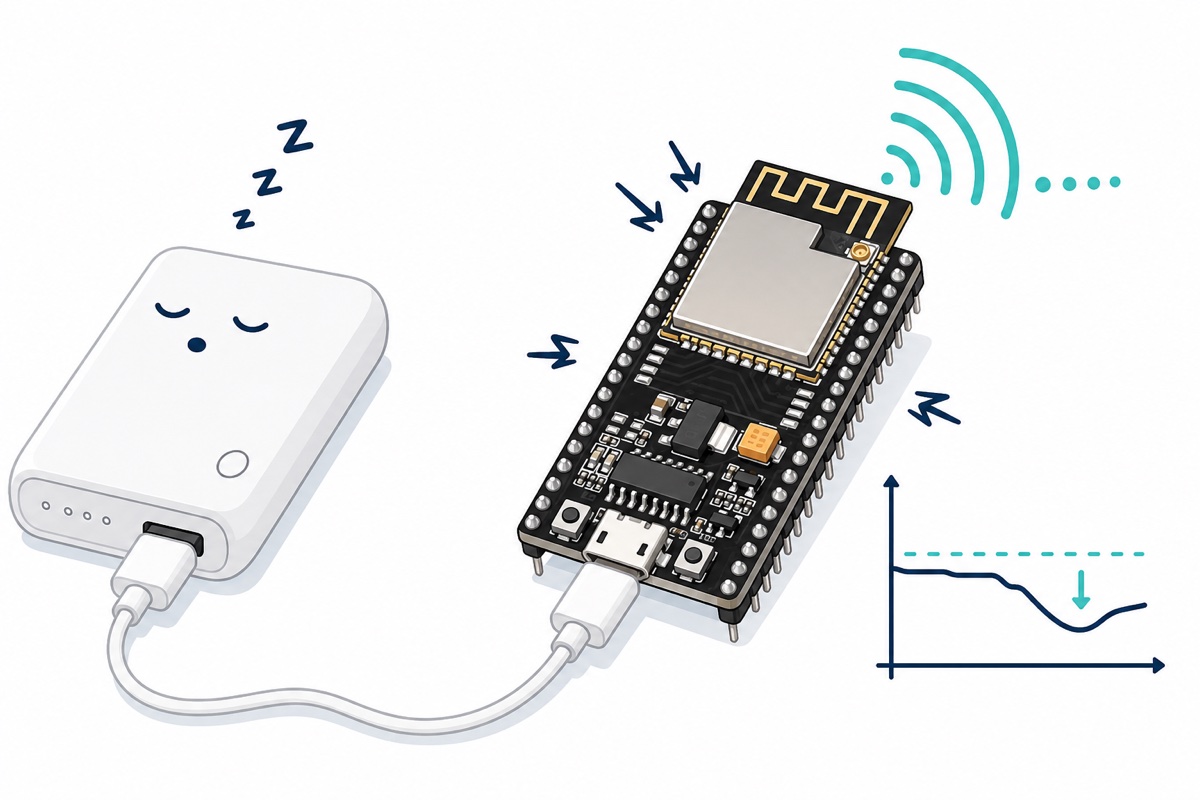
The ESP32’s radio is what surprises people. Espressif’s datasheet measures 240mA typical transmitting 802.11b at +19.5dBm — averaged over a 50% duty cycle, so instantaneous bursts run higher — and its hardware design guidelines demand a 3.3V supply of no less than 500mA, warning that transmit bursts cause “a sudden increase in the current draw, causing power rail collapse”.
When the rail sags, the chip’s supervisor prints Brownout detector was triggered on the serial monitor and reboots the board. The classic pattern on a NodeMCU ESP32 DevKit: the sketch runs fine until WiFi.begin(), then resets in a loop. The code is innocent — the supply failed a millisecond stress test.
Parts list
 NodeMCU ESP32 Wi-Fi + Bluetooth Development Board CH340/CP2012 - For IOT Project - ESP-32(CP2102)
 3.7V 18650 Battery Rechargeable Li-Ion Battery 1200mAh 2200mAh 3200mAh Flat Top - 18650 Li-Ion Battery (2200mAh)
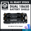 Dual 18650 Lithium Battery Holder Shield V3 Power Module 5V USB 3V Pin Output Charging
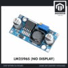 LM2596S DC-DC Buck Converter Step Down Power Module 4-40V to 1.25-37V Voltage Regulator Board - LM2596S BUCK CONVERTOR
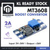 MT3608 Adjustable Step-up Convertor Boost Converter Switching Boost Converter for Arduino Project
Which of the three power paths should I choose?
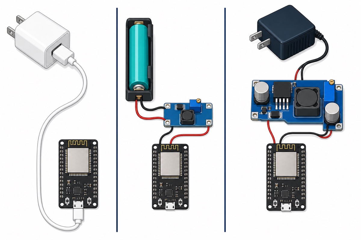
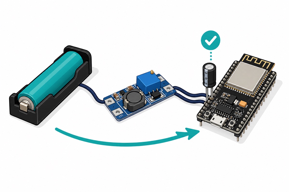
The DevKit’s three power paths — USB, battery plus boost, higher voltage plus buck — all end the same way: a clean 5V in, which the onboard regulator turns into 3.3V.
| Path | Parts | Best for | Watch out |
|---|---|---|---|
| USB | Phone charger or power bank + micro-USB cable | Desk projects, first uploads | Weak ports and thin cables sag; power banks auto-sleep |
| One 18650 + boost | 18650 cell + holder + MT3608 set to 5V → VIN | Portable and battery projects | Set 5.0V before connecting; never cell → 3V3 |
| Higher voltage + buck | 9–12V adapter or pack + LM2596 set to 5V → VIN | Fixed installs sharing a 12V rail | Set 5.0V before connecting; needs ~2V headroom |
Andreas Spiess bench-tests most of these options — worth a watch before committing:
Can I just power the ESP32 from USB?
USB is the simplest ESP32 power supply — a good 5V charger rated 1A or more runs the board all day. The traps sit at the margins: a computer’s USB 2.0 port is specced for only 500mA, exactly the ESP32’s minimum, and long thin cables drop enough voltage during bursts to brown out even a strong charger’s output.
Power banks add a quirk: an idle ESP32 draws so little that many banks decide nothing is connected and switch off — a project that dies after 30 seconds is hitting auto-sleep, not a bug. Charge-only cables are the opposite trap: the board powers up but uploads fail — they carry no data lines.
Can a single 18650 connect straight to the 3V3 pin?
No — an 18650 on the 3V3 pin damages boards. A Li-ion cell sits between 3.0V and 4.2V, while the ESP32’s supply pins are rated to an absolute ceiling of 3.6V in Espressif’s datasheet. Feeding the 3V3 pin also bypasses the onboard regulator, so a fresh cell puts 4.2V on the bare chip.
The VIN pin does not rescue the idea either. The DevKit’s AMS1117-style regulator needs up to 1.3V of headroom above its 3.3V output (guaranteed maximum dropout, specified at 0.8A load) (AMS1117 datasheet), so VIN wants roughly 4.6V minimum — and a single cell spends its whole life below that. VIN accepts 5V to about 12V, but 5V is the sweet spot; anything higher just becomes heat.
| Where you feed power | Safe input | Notes |
|---|---|---|
| Micro-USB port | 5V | Simplest; goes through the onboard 3.3V regulator |
| VIN pin | ~5–12V (5V ideal) | Needs ~4.6V minimum — one bare Li-ion cell is too low |
| 3V3 pin | Regulated 3.0–3.6V only | Bypasses the regulator; never a Li-ion cell directly |
The correct single-cell recipes: an MT3608 boost to 5V into VIN, or a proper low-dropout 3.3V regulator into 3V3. For charging, our TP4056 18650 charging guide covers protection and why Li-ion never charges unattended.
When do I use the LM2596 buck, and when the MT3608 boost?
The LM2596 steps down: 4.5–40V in, adjustable 1.2–37V out, 3A rated (TI’s LM2596 datasheet) — the blue module boards are typically labelled 7–35V in, and 2A is the realistic thermal ceiling. It fits projects that already have a higher-voltage supply, such as a 12V LED-strip adapter or solar controller. Set the output to 5.0V before the ESP32 ever touches it — these modules ship at random voltages, and our LM2596 adjustment guide walks through the multi-turn trimmer.
The MT3608 steps up: 2–24V in, up to 28V out, a 2A-class step-up converter with a 4A internal switch current limit (MT3608 datasheet). Boosting one 18650 to 5V, plan on roughly 1A continuous — plenty for a DevKit, not enough to also run servos. Same rule: trim it to 5.0V under a meter first, and remember a boost can only go above its input.
What about the dual 18650 battery shield?
The dual 18650 battery holder shield bundles the job into one board: it holds two cells, charges them over micro-USB, shows charge on four LEDs, and gives a regulated 5V USB output plus a 3V pin header. A short cable from its 5V output to the DevKit’s micro-USB is all the wiring it needs.
Two caveats before you rely on it. The two holders sit in parallel, not series — you can read that off the board itself: it boosts a 3.7–4.2V single-cell rail up to 5V, and charges through a single-cell charger, neither of which would work with 7.4V from a series pair. Parallel means capacity adds while voltage stays put, so fit two cells of the same type and charge state; a gap wider than about 0.2V lets the fuller cell dump current into the emptier one the moment you insert it. Skip the 3V pin too: it leaves no sag margin for WiFi bursts — use the 5V USB output.
How do I stop brownouts for good?
ESP32 brownout prevention is the same checklist whichever path you chose:
- Thick, short wires. Every centimetre of thin jumper is resistance, and resistance turns a 240mA burst into a voltage dip.
- A bulk capacitor at the board. A 470–1000µF electrolytic across VIN and GND, close to the ESP32, rides through each burst — the hobbyist-grade version of Espressif’s own 10µF-minimum rule.
- Real headroom. Pick a supply rated at least double the expected draw — a “1A” adapter that sags at 800mA is a brownout generator.
- Separate rails for hungry loads. Servos, motors and LED strips get their own 5V supply, sharing only ground.
- Measure under load. A no-load reading proves nothing — probe the 5V and 3V3 pins while WiFi is transmitting (our digital multimeter guide shows how).
The SIM800L GSM module fails the same way, only harder — our SIM800L brownout guide is this exact lesson with a 2A burst.
Common mistakes we see from real customers
Wiring a full Li-ion cell to the 3V3 pin. The board often survives for a while, which makes the eventual random failure look like a defect. It was out of spec from the first minute.
Blaming the code for brownout resets. When a sketch dies exactly at WiFi.begin(), people reflash and swap libraries — but the serial monitor already named the culprit. Brownout detector was triggered is a power message, not a software bug.
Connecting a converter before adjusting it. Both the LM2596 and MT3608 ship at random output voltages, and a module still set to 12V will cook a DevKit through VIN. Trim to 5.0V with only meter probes on the output.
Running a servo off the DevKit’s own rail. The onboard regulator can just about feed the ESP32 itself; the first servo stall resets the board. Hungry loads get their own supply, joined at ground only.
FAQ
Why does my ESP32 keep printing “Brownout detector was triggered”?
Your supply is sagging during WiFi transmit bursts, which spike past 240mA. Use a supply good for at least 500mA, shorten and thicken the wiring, and add a 470–1000µF capacitor near the board.
Can I power an ESP32 with one 18650 battery?
Yes, but never directly. A full cell’s 4.2V is above the 3V3 pin’s 3.6V limit, and the whole 3.0–4.2V range sits below the VIN pin’s ~4.6V minimum. Boost it to 5V with an MT3608 into VIN, or use a low-dropout 3.3V regulator into 3V3.
What voltage can the ESP32 VIN pin accept?
Practically 5–12V, with 5V the sweet spot. The onboard AMS1117-style regulator needs about 4.6V to hold a stable 3.3V rail, and everything above 5V turns to heat.
Should I just disable the brownout detector in software?
No. It reports a real voltage collapse — disabling it trades a clean reset for random crashes and corrupted flash writes. Fix the supply and the message disappears.
Last updated August 2026. Stuck? Chat with us on WhatsApp.

Pingback: Which ESP32 to Buy: DevKit V1, WROOM-32E, S3 or C3
Pingback: Choose a DC Power Supply: Volts, Amps, Barrel Jacks