

Tutorials
TM1637 vs MAX7219: Which 7-Segment Display Should You Buy?
Jul
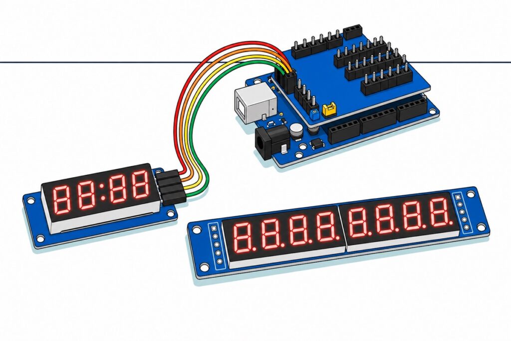
Buy the TM1637 4-digit module when your readout is a clock and needs a colon, and the MAX7219 8-digit module when you need five digits or more, a decimal point, or several panels. The other half of the decision is what is in the bag: our TM1637 arrives with its header on, the MAX7219 with five bare pads.
What is the quick answer: TM1637 or MAX7219?
The TM1637 and MAX7219 modules answer one question in opposite ways: how many digits, against how many Arduino pins you can spare.
| TM1637 module (4DI1637) | MAX7219 module (8DI7291) | |
|---|---|---|
| Digits | 4 | 8 (two blocks of four) |
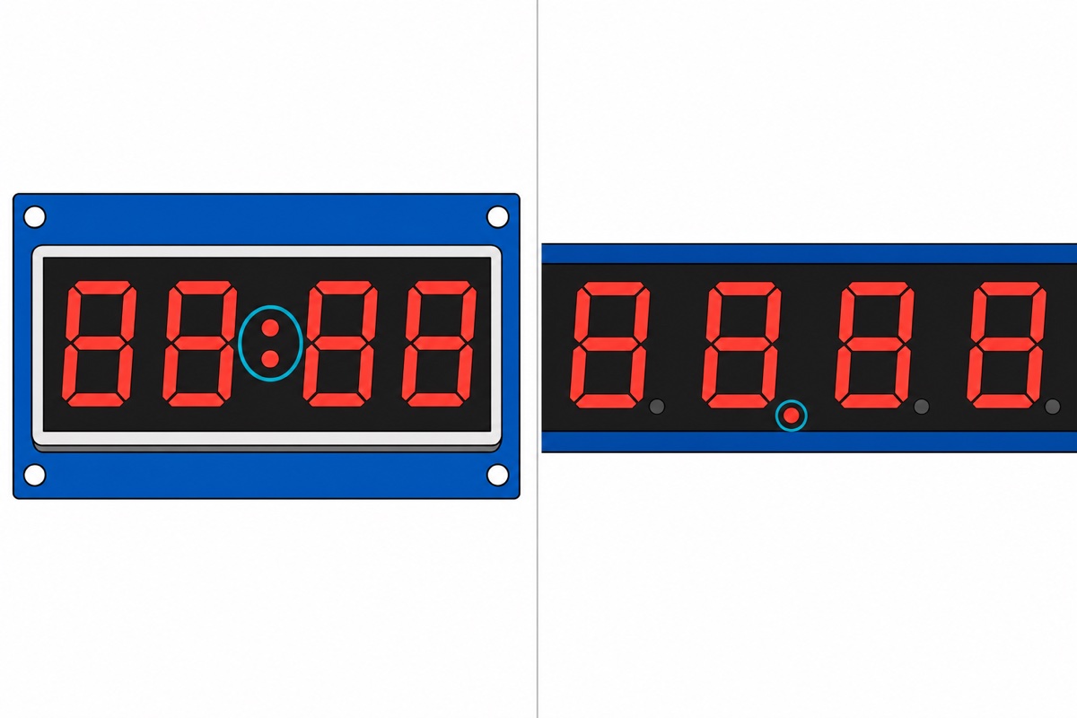
| Separator | Fixed centre colon, no decimal points | Decimal point on every digit, no colon |
| Interface | Two-wire (CLK + DIO), proprietary — not I2C | Three-wire serial, SPI-style (DIN, CS, CLK) |
| Uno pins for one module | 2 signal pins | 3 signal pins |
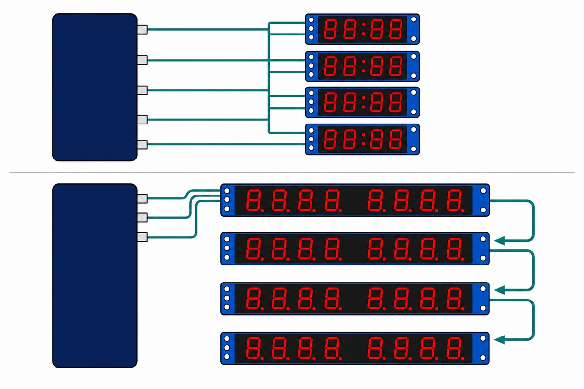
| Uno pins for N modules | 1 + N (shared CLK, one DIO each) | 3, however many you chain |
| Board size | ~42 x 25 mm, four M2 corner holes | ~82 x 15 mm strip, four 3 mm holes |
| Brightness control | 8 steps, set in the display command | 16 duty steps, set in the intensity register |
| How it ships from us | 4-pin right-angle header already soldered | Five bare pads — header not fitted |
| Arduino library | TM1637 by Avishay Orpaz | LedControl by Eberhard Fahle |
Parts list — both displays, an Uno, and the wiring that reaches them
 TM1637 Based 4 Digit 7 Segment Display 4 Pin Only LED Display Module For Arduino IOT Application
 MAX7219 8 Digit 7 Segment Display LED Digit Display Module For Arduino IOT Application
 Arduino Uno Compatible SMD UNO R3 with Type B Cable - ATMEGA328P with CH340G-Microcontroller Project
 Sensor Shield V5.0 Arduino Uno R3 Shield For Arduino Protoype Application
 40pcs Dupont Wire 10cm 20cm 30cm for Breadboard DIY Experiment Jumper Wire Breadboard wire - DUPONT WIRE F-F 20CM
 2.54mm Pin Header Female Male Single Row Header 40P Connector Black White Red Yellow Green Blue - 40P MALE HEADER (BLACK)
Optional: we solder the header for you
| Item | Price | Qty | |
|---|---|---|---|
 Soldering Service for Circuit Boards & Electronics - 5 Pins Soldering ServiceSOLSE05 Soldering Service for Circuit Boards & Electronics - 5 Pins Soldering ServiceSOLSE05 | RM0.80 |
Five pins on the MAX7219, soldered before it ships. This service is consultation-first, so message us on WhatsApp before you add it to the cart.
Why are the TM1637’s two wires not I2C?
The TM1637’s link looks exactly like I2C on a scope: data starts when DIO falls while CLK is high, ends when it rises, and the chip acknowledges by pulling DIO low on the eighth clock’s falling edge. Titan Micro’s TM1637 datasheet states the deciding fact: the protocol “is not equal to I2C bus protocol totally because there is no slave address”.
Remove the address and three things follow. There is no Wire route and no reason to use A4 and A5: the library bit-bangs the link, so any two ordinary digital pins work, and DIO is open-drain — the library only pulls it low or releases it to the module’s pull-up. Bytes go out least significant bit first, where I2C is most significant first. And two modules sharing one CLK and DIO both latch the same bytes, because nothing says who is being addressed. So it scales by pin count: share CLK, one DIO each.
How does the MAX7219 fit 64 digits onto three pins?
The MAX7219 speaks in fixed 16-bit packets. Analog Devices’ MAX7219/MAX7221 datasheet spells the frame out: bits shift into an internal 16-bit register on each rising CLK edge, the first in is D15, D8–D11 carry the register address, D0–D7 the data, and the word latches on LOAD/CS’s rising edge. That is SPI in all but name — though the datasheet saves the phrase “fully SPI compatible” for the MAX7221 twin, because on the MAX7219 data shifts in on every rising CLK edge whatever CS is doing; CS only latches.
Cascading is the clever part. Whatever enters DIN reappears at DOUT 16.5 clock cycles later, so a second packet shoves the first out of module 1 into module 2. Wire DOUT to the next DIN, tie every CS together, and reaching the fourth module means four packets — one real, three no-ops — latched by one rising CS edge. LedControl drives eight devices, so sixty-four digits still cost three pins. That asymmetry is the buying argument.
Which one should you buy for your Arduino project?
The TM1637’s colon is a category of project, not decoration: clocks, countdowns, lap timers. Our DS3231 clock build puts the time on a 16×2 LCD; a TM1637 does it in a quarter of the space on two pins. The MAX7219 owns fractional readings and long numbers.
| If your readout is… | Buy |
|---|---|
| A clock or timer in HH:MM or MM:SS | TM1637 4-digit module |
| Four digits or fewer on a crowded Uno | TM1637 4-digit module |
| A sensor reading with a decimal place | MAX7219 8-digit module |
| Five digits or more, or two panels side by side | MAX7219 8-digit module |
| Words, names or menus | Neither — see our OLED monitor guide |
What is in the bag, and the header the MAX7219 needs
The TM1637 module ships ready to wire: its four-pin right-angle header is factory-soldered at the short end, and the order is CLK, DIO, VCC, GND — silkscreened underneath, so flip it over first.
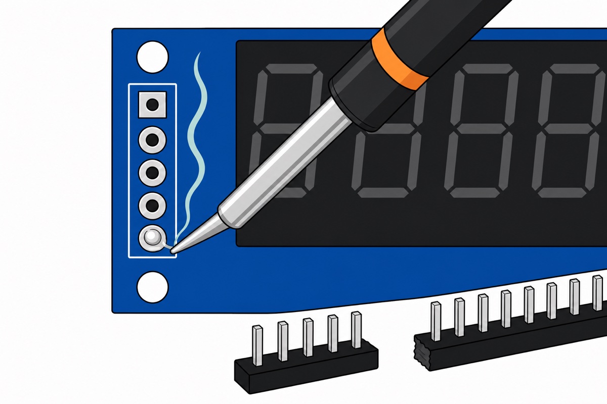
The MAX7219 module ships differently, and that is the fact worth knowing before you order. Its five input pads — VCC, GND, DIN, CS, CLK, with VCC on the square pad that marks pin 1 — are bare plated through-holes with no header fitted, as are the five cascade pads at the far end. The bag holds the display, nothing else. Hence the 40-pin male header strip in the parts list: snap off five pins and solder five joints, deciding which face the pins stand out of before the iron is hot. Or add the 5-pin soldering service — that listing is consultation-first, so message us on WhatsApp first.
One safety note, the only real hazard here. A soldering iron tip sits near 350 °C, hot enough to scar before you feel it, and flux smoke is an irritant: heat-proof surface, iron back in its stand between joints, a window open or a fan across the bench. Our soldering guide covers this row.
How much current do eight lit digits draw?
The MAX7219 never lights eight digits at once. A hardware oscillator scans the eight digit drivers in turn at 500–1300 Hz, so at any instant one digit is on and up to eight of its segments — seven bars plus the decimal point — draw current. Peak segment current is hardware, not code: one resistor between V+ and the chip’s ISET pin, with the segment drivers sourcing about 100 times the current entering it. The datasheet’s floor for that resistor, 9.53 kΩ, puts a segment near 40 mA, and eight of those is 320 mA. With all eight digits showing 8. at once, one of them is always at that peak, so the peak is also the average — hence the datasheet’s typical 330 mA with all segments and the decimal point on. Blank digits draw nothing in their slot, so a two-digit readout averages roughly a quarter of that even though its peak is unchanged.
A USB 2.0 port budgets 500 mA and the Uno wants part of it, so a full-brightness panel on the same cable sits close to the edge, and the symptom is a board that resets as the display fills up. Turn the intensity down — that register is a duty-cycle control running 1/32 to 31/32 in sixteen steps, so average current falls with it — or give the display its own 5 V supply, wired to the module’s VCC and GND with the grounds tied. Keep it off the shield’s screw terminal: the small jumper beside that terminal joins it to the Uno’s own 5 V rail, so a second supply landing there ends up fighting the USB one. Same current-budget lesson as our WS2812 guide.
That current-setting resistor is already fitted on our module, so brightness here is software only. The TM1637 has no equivalent: it sets segment current inside the chip, giving eight pulse-width steps with nothing to solder or trim. Both chips scan in hardware, so neither flickers and neither needs your loop() to refresh it.
How do you wire and code each one?
With the MAX7219’s five pins soldered on, both modules present male pins — the TM1637’s are factory-fitted — and the Arduino Uno‘s headers are female sockets. The Sensor Shield V5.0 settles it in one press-fit: it re-presents every digital pin as a male S pin in a G/V/S triple, so plain F-F jumpers bridge the two.
| TM1637 pin | Goes to |
|---|---|
| CLK | S pin of shield column 2 → D2 |
| DIO | S pin of shield column 3 → D3 |
| VCC | Any V pin on the shield → Uno 5V |
| GND | Any G pin on the shield → Uno GND |
// TM1637 4-digit display - minutes:seconds with the colon lit.
// Library: "TM1637" by Avishay Orpaz (Library Manager) - header TM1637Display.h
#include <TM1637Display.h>

const uint8_t PIN_CLK = 2;   // any two ordinary digital pins
const uint8_t PIN_DIO = 3;

TM1637Display display(PIN_CLK, PIN_DIO);

void setup() {
  display.setBrightness(3);  // 0 = dimmest, 7 = brightest
  display.clear();
}

void loop() {
  static unsigned long shown = 0;
  unsigned long secs = millis() / 1000UL;      // seconds since power-up
  if (secs == shown) return;                   // only redraw when it changes
  shown = secs;

  unsigned int mm = (secs / 60UL) % 100UL;     // 0..99 minutes
  unsigned int ss = secs % 60UL;

  // 0b01000000 lights the colon (bit 6 = the second digit's decimal-point bit)
  display.showNumberDecEx(mm * 100 + ss, 0b01000000, true);
}| MAX7219 pin | Goes to |
|---|---|
| VCC | Any V pin on the shield → Uno 5V |
| GND | Any G pin on the shield → Uno GND |
| DIN | S pin of shield column 11 → D11 |
| CS | S pin of shield column 10 → D10 |
| CLK | S pin of shield column 13 → D13 |
// MAX7219 8-digit display - a stopwatch reading to one decimal place.
// Library: "LedControl" by Eberhard Fahle (Library Manager)
#include <LedControl.h>

const uint8_t PIN_DIN = 11;
const uint8_t PIN_CLK = 13;
const uint8_t PIN_CS  = 10;

LedControl lc(PIN_DIN, PIN_CLK, PIN_CS, 1);  // 1 = one module in the chain

void setup() {
  lc.shutdown(0, false);     // the chip powers up blanked - this wakes it
  lc.setIntensity(0, 2);     // 0..15 duty steps; low keeps the current sane
  lc.clearDisplay(0);
}

// Digit 0 is the RIGHT-hand digit on this board.
void showTenths(unsigned long tenths) {
  uint8_t pos = 0;
  do {
    lc.setDigit(0, pos, (byte)(tenths % 10), pos == 1);  // dp on the units digit
    tenths /= 10;
    pos++;
  } while ((tenths > 0 || pos < 2) && pos < 8);
}

void loop() {
  static unsigned long shown = 0;
  unsigned long tenths = millis() / 100UL;
  if (tenths == shown) return;
  shown = tenths;
  showTenths(tenths % 100000000UL);   // 8 digits hold up to 99999999
}
LedControl bit-bangs the three lines with shiftOut() rather than the Uno’s SPI peripheral, so D11, D13 and D10 are a convention, not a requirement — any three digital pins work. Leave setScanLimit() alone, though: the datasheet warns that scanning three digits or fewer makes the individual digit drivers dissipate excessive power unless that current-setting resistor is raised to match, and on this module it is fixed. Blank spare digits with lc.setRow(0, pos, 0x00) instead. To watch this hardware and library on a bench:
Common mistakes we see from real customers
The MAX7219 is wired correctly and stays dark. Designed behaviour, twice over. The datasheet: “On initial power-up, all control registers are reset, the display is blanked, and the MAX7219/MAX7221 enter shutdown mode.” LedControl’s constructor then returns it to shutdown so nothing flashes while your sketch sets up. Nothing lights until lc.shutdown(0, false) runs — hence the first line of setup().
It lights up but shows random bars. That is the decode-mode register at address 0x09: the MAX7219 either decodes a plain number into segments for you (BCD Code B) or takes a raw segment bitmap, and that register picks which. LedControl sends raw bitmaps and sets decode mode to zero at startup, so hand-written code that switches Code B back on makes every later byte read as the wrong kind of thing.
The number reads backwards. Digit 0 is the right-hand digit on this board, so the least significant digit goes at position 0 and you work leftwards, as the sketch does — which is why its decimal point lands on position 1. To be certain, light position 0 alone and watch which end responds.
The sketch will not compile. Both names are crowded in Library Manager: the TM1637 sketch above needs Avishay Orpaz’s library, header TM1637Display.h, and the other TM1637 entries use different class and method names. For the MAX7219 take LedControl — MD_MAX72xx is the 8×8 matrix library and shares none of its API.
The Uno resets when the display fills with eights. Not a code bug — that is the current budget above meeting a 500 mA USB port. And people still buy the eight-digit board for a colon clock: it has decimal points and no colon, so that job is the TM1637’s.
FAQ
Can I connect a TM1637 to the Arduino’s I2C pins A4 and A5?
Physically yes, but there is no benefit and no Wire route: the protocol carries no device address, so it cannot share a bus with I2C parts. Use any two free digital pins.
Does the MAX7219 module come with the pin header attached?
No — it ships with five bare plated holes at each end and the bag holds the display only. Fit five pins off a 40-pin header strip, or add our 5-pin soldering service.
How many displays can one Arduino Uno run?
Chained MAX7219 modules cost three pins however many you add, and LedControl handles eight — sixty-four digits. TM1637 modules cost one pin each, since they share CLK but need their own DIO.
Can a 7-segment display show letters or words?
Only the letters that fit seven bars — A, b, C, d, E, F, H, L, P and a few more. Anything that must spell words needs a character LCD or a small OLED.
Do these modules work with an ESP32 or NodeMCU?
Power both from 5 V. The MAX7219’s supply range is 4.0–5.5 V and its data inputs are specified to read a logic high at 3.5 V, so a 3.3 V board drives them just under the guaranteed threshold; a level shifter on DIN, CS and CLK makes it dependable. The TM1637’s open-drain DIO idles at the module’s own supply, so it wants one there too — our board comparison has the full 3.3 V and 5 V story.
Last updated August 2026. Stuck? Chat with us on WhatsApp.
