

Tutorials
DHT11 Temperature Monitor with OLED: ESP32 Arduino Guide
Jun
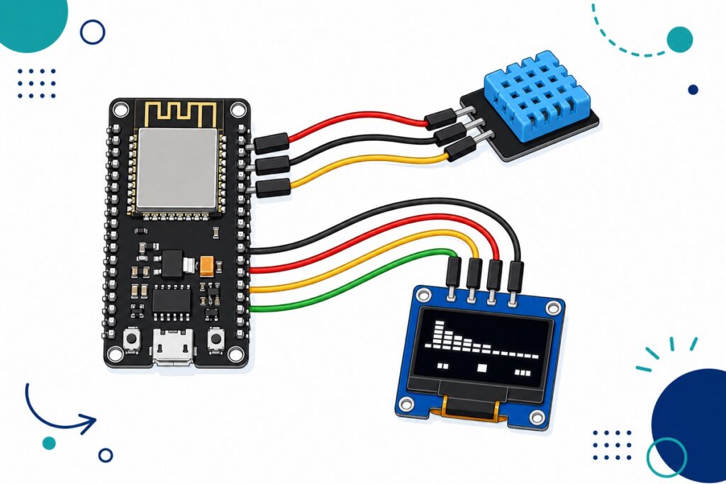
Connect the DHT11 module’s signal pin to the ESP32’s GPIO4, the OLED’s SDA and SCL to GPIO21 and GPIO22, power both from the 3V3 pin, then run one sketch with the Adafruit DHT and SSD1306 libraries. Everything runs at 3.3V and needs no extra resistors — the 3-pin DHT11 module already has its pull-up on board.
What parts do you need for this ESP32 weather station?
The NodeMCU-32S ESP32 board is the brain: WiFi-capable, 3.3V logic, and forgiving for a first project. It programs over micro-USB, not USB-C, so have a micro-USB data cable ready. Its USB chip is a CP2102, so your computer needs the Silicon Labs CP210x driver — not the CH340 driver other boards use.
If no COM port appears even with the driver installed, work through our ESP32 not detected guide before blaming the code.
Parts list
 NodeMCU ESP32 Wi-Fi + Bluetooth Development Board CH340/CP2012 - For IOT Project - ESP-32(CP2102)
 DHT 11 DHT 22 Temperature and Humidity Sensor DHT22 High Sensitivity Sensor DHT11 For Aduino IOT - DHT11 SENSOR
 0.96‘ OLED Display Module Blue White Screen I2C IIC Serial 128X64 LCD Display Board - 0.96' OLED WHITE
 40pcs Dupont Wire 10cm 20cm 30cm for Breadboard DIY Experiment Jumper Wire Breadboard wire - DUPONT WIRE F-F 20CM
How do you wire the DHT11 and OLED to the ESP32?
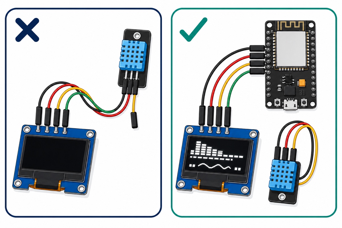
The 0.96″ OLED talks I2C, and the ESP32’s default I2C pins in Arduino are GPIO21 (SDA) and GPIO22 (SCL), so no remapping is needed. The DHT11 uses its own single-wire protocol on any free GPIO; we use GPIO4.
| Module pin | ESP32 pin | Notes |
|---|---|---|
| OLED GND | GND | First pin on this display — check the silkscreen |
| OLED VCC | 3V3 | Second pin, not first |
| OLED SCL | GPIO22 | Default Arduino I2C clock |
| OLED SDA | GPIO21 | Default Arduino I2C data |
| DHT11 S (signal) | GPIO4 | Any free GPIO works; sketch uses 4 |
| DHT11 VCC | 3V3 | Module accepts 3.3–5.5V |
| DHT11 GND | GND | — |
One warning before you plug in: this OLED’s header reads GND, VCC, SCL, SDA left to right — the reverse of the VCC-first order on many other modules. Wiring red to the first pin out of habit puts the supply across the display backwards, the classic way these OLEDs die. Match the silkscreen, never the wire colours in someone else’s photo.
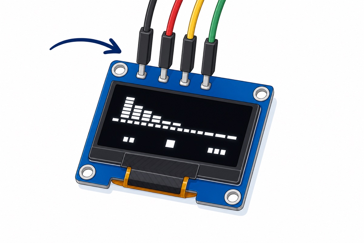
Now the good news: skip the 10k pull-up resistor most DHT11 tutorials tell you to add. That advice is for the bare 4-pin sensor; ours is the 3-pin module version with the pull-up already on its small black PCB. Connect S, VCC and GND and wiring is finished — and since everything runs at 3.3V, no level shifting is needed either.
Which libraries and code make the display work?
The Adafruit stack drives both parts, installed from Arduino IDE’s Library Manager (Sketch → Include Library → Manage Libraries). Search DHT sensor library by Adafruit and accept the prompt to install its Adafruit Unified Sensor dependency, then install Adafruit SSD1306, which pulls in Adafruit GFX the same way.
The sketch reads once every two seconds using millis() instead of delay(), so the loop never blocks. Aosong’s DHT11 datasheet specifies a sampling period of at least two seconds, and the Adafruit library enforces the same two-second minimum internally — polling faster just returns cached or failed reads. Two seconds is the sensor’s own pace — and lets the identical sketch run a DHT22 unchanged.
#include <Wire.h>
#include <Adafruit_GFX.h>
#include <Adafruit_SSD1306.h>
#include <DHT.h>

#define SCREEN_WIDTH 128
#define SCREEN_HEIGHT 64
#define OLED_ADDR 0x3C      // run an I2C scanner if the screen stays blank
#define DHTPIN 4            // DHT11 module S pin
#define DHTTYPE DHT11       // change to DHT22 if you bought that variant

Adafruit_SSD1306 display(SCREEN_WIDTH, SCREEN_HEIGHT, &Wire, -1);
DHT dht(DHTPIN, DHTTYPE);

const unsigned long READ_INTERVAL = 2000; // DHT11 needs at least 2 s between reads
unsigned long lastRead = 0;

void setup() {
  Serial.begin(115200);
  dht.begin();
  if (!display.begin(SSD1306_SWITCHCAPVCC, OLED_ADDR)) {
    Serial.println("SSD1306 not found - check wiring and address");
    while (true) delay(10);   // stop here, nothing to show
  }
  display.clearDisplay();
  display.setTextColor(SSD1306_WHITE);
  display.setTextSize(1);
  display.setCursor(0, 0);
  display.println("DHT11 monitor ready");
  display.display();
}

void loop() {
  if (millis() - lastRead < READ_INTERVAL) return; // non-blocking wait
  lastRead = millis();

  float h = dht.readHumidity();
  float t = dht.readTemperature(); // Celsius

  display.clearDisplay();
  display.setCursor(0, 0);

  if (isnan(h) || isnan(t)) {
    display.setTextSize(1);
    display.println("Sensor read failed");
    display.println("Check DHT11 wiring");
  } else {
    display.setTextSize(1);
    display.println("Temperature:");
    display.setTextSize(2);
    display.print(t, 1);
    display.println(" C");
    display.setTextSize(1);
    display.println("Humidity:");
    display.setTextSize(2);
    display.print(h, 1);
    display.println(" %");
  }
  display.display();
}
What if your OLED is at address 0x3D instead of 0x3C?
SSD1306-class displays live at one of two I2C addresses — 0x3C or 0x3D, set by the controller’s SA0 address bit. 0x3C is by far the common default and is what the sketch uses.
If the screen stays dark, do not guess — scan. The ESP32 Arduino core ships a scanner at File → Examples → Wire → WireScan; upload it, open Serial Monitor, and it prints every I2C address it finds. Whatever it reports goes into OLED_ADDR; nothing found means a wiring problem, not an address problem.
Should you buy the DHT11 or the DHT22?
The DHT11 and DHT22 are two variants of the same sensor — our listing carries both — and the honest answer is that each has a job. The figures below are from Adafruit’s DHT guide; the sampling rate follows Aosong’s own DHT11 datasheet, which is stricter than Adafruit’s 1 Hz figure.
| Spec | DHT11 | DHT22 |
|---|---|---|
| Temperature range | 0–50°C | −40 to 80°C |
| Temperature accuracy | ±2°C | ±0.5°C |
| Humidity range | 20–80% RH | 0–100% RH |
| Humidity accuracy | ±5% | ±2–5% |
| Max sampling rate | 0.5 Hz (every 2 seconds) | 0.5 Hz (every 2 seconds) |
For a Malaysian room, office or grow cabinet, the DHT11’s 0–50°C window and ±2°C accuracy are entirely adequate. Choose the DHT22 for readings below 0°C (fridge logging), humidity outside 20–80%, or tighter accuracy for something like an incubator. In code the only change is #define DHTTYPE DHT22.
Why is the screen blank or the reading “nan”?
A nan (not a number) reading means the DHT library asked the sensor and got silence. Check three things in order: the S wire is really on GPIO4 and seated firmly, DHTTYPE matches your actual sensor (a DHT11 read as DHT22 fails), and VCC/GND go to 3V3 and GND. Copied code often polls too fast as well — keep at least two seconds between reads.
A blank OLED with a working sensor is almost always the I2C side: SDA and SCL swapped, the wrong address in OLED_ADDR, or GND/VCC reversed on that back-to-front header. Run the WireScan sketch first — it tells you in ten seconds whether the display is alive and where it lives.
A reading 1–2°C off your aircond remote is not a fault either — that is within the DHT11’s ±2°C spec.
Can you use an Arduino Uno instead of the ESP32?
An Arduino Uno runs this project with the same three libraries and only pin changes: OLED SDA to A4, SCL to A5, and the DHT11 signal to digital pin 2 (update DHTPIN). Power both modules from the Uno’s 5V pin — the DHT11 module accepts 3.3–5.5V, and this OLED module regulates its supply on board, which is why every classic Uno OLED build feeds it 5V.
What you lose is WiFi: the Uno shows readings locally but can never send them to your phone. If a connected weather station is the end goal, start on the ESP32 — our ESP32 vs ESP8266 vs Uno comparison breaks down when each board makes sense.
Common mistakes we see from real customers
The most expensive pattern is wiring the OLED red-wire-first from muscle memory. On this display that puts VCC on the GND pin, and a reversed supply can kill the module instantly — it is the one mistake in this build that hardware does not forgive.
Next is following a bare-sensor diagram with the 3-pin module: hunting for a fourth pin, adding an unnecessary pull-up, or trusting a diagram’s wire colours instead of the S, VCC and GND markings printed on the module itself. The module’s own silkscreen always wins.
On the software side, the usual trap is pasted code with DHTTYPE DHT22 left in, which makes a healthy DHT11 return nan forever. And plenty of first builds stall earlier still, on a charge-only micro-USB cable that powers the board but cannot upload.
FAQ
Can the DHT11 measure negative temperature like a fridge?
No. The DHT11 reads 0–50°C, so it stops at freezing. For fridge or freezer logging, choose the DHT22 variant, which reads down to −40°C — the wiring and sketch stay the same apart from one line.
Do I need to add a 10k resistor for the DHT11?
Not with our module. The 3-pin DHT11 module has the pull-up resistor built onto its PCB, so it connects straight to the ESP32 with three wires. Only the bare 4-pin sensor needs an external pull-up.
Why does my OLED show nothing even though the code uploads fine?
Usually the I2C address or the wiring. Run the WireScan example from the ESP32 core: if it prints 0x3D, change OLED_ADDR; if it finds nothing, recheck SDA on GPIO21, SCL on GPIO22, and that GND and VCC follow this display’s GND-first pin order.
Can I power this project from a power bank?
Yes — the whole circuit draws little current, and a power bank into the micro-USB port makes it portable. Some power banks switch off on light loads; our powering ESP32 projects guide covers that and longer-term options.
Do I need a breadboard for this build?
No. The ESP32 board, DHT11 module and OLED all carry male header pins, so seven female-to-female jumper wires connect everything directly. Use a breadboard only if you prefer a tidier mount or plan to add more sensors later.
Last updated August 2026. Stuck? Chat with us on WhatsApp.

Pingback: DHT11 vs DHT22: Which Humidity Sensor to Buy