

Tutorials
Pulse Sensor Arduino: Heart Rate with MAX30102
Jul
Both sensors on this page measure light, not heartbeats. An LED shines into your fingertip, a detector reads what comes back, and every BPM figure is derived from the timing of that wobbling light level. The analog pulse sensor plots it on an Uno in five minutes with no library — yellow to A0, red to 5 V, black to GND, then analogRead() into the Serial Plotter. The MAX3010x module takes longer: it needs its header soldered on, and one register read before you install any library.
Is any of this a medical device?
No. The pulse sensor and the MAX3010x module are hobby and science-fair parts, not medical instruments. Neither is medically accurate, neither is certified, and no number either one produces may be used to diagnose anything, monitor a condition, or decide anything about anyone’s health. If you have a health concern, see a doctor — not an Arduino.
Treat every figure the build produces as a demonstration of an optical principle. That is not a disclaimer, it is what the hardware does, as the rest of this guide explains. A blood-oxygen percentage especially: a defensible SpO₂ figure needs a calibrated red-to-infrared absorption ratio validated against certified equipment, so demonstrate heart rate and the raw waveform and say so in your write-up. Hardware safety is short: low-voltage DC off a USB cable, nothing near mains, VIN on 5 V or 3.3 V only, and the pulse sensor’s RED lead on the 5 V or 3.3 V rail and nowhere else.
What is a “heart rate sensor” actually sensing?
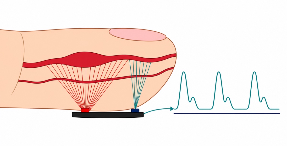
The pulse sensor and the MAX3010x both do photoplethysmography, a long word for a simple trick. An LED pushes light into your fingertip; most is absorbed and scattered, and a small fraction returns onto a photodiode. Each heartbeat swells the arteries in that tissue, so more light is absorbed and slightly less comes back out.
That ripple is around one percent of the steady light level under it, so the round black pulse sensor board is mostly not a sensor: the chip on it is an amplifier that strips the steady part away and blows up what is left. Two surface-mount resistors set how big the result comes out — one feeding the LED, one loading the detector. An amplified ripple has to swing down as well as up, so the board parks its output at half the supply and rides the beat on top of that — which is why A0 sees a voltage near mid-scale, analogRead() about 512 on a 5 V board, with a bump once per beat instead of a reading that starts at zero.
Nothing in that signal is a number of beats per minute. BPM is a guess your code makes by measuring the gap between two bumps and dividing 60 000 ms by it — hence a graph before a figure below, and hence the nonsense the moment your finger shifts, because a knuckle twitch makes a bump the code cannot tell from a heartbeat.
Parts list — both sensors, an Uno, and the wiring that reaches them
 Pulse Sensor Module Heart Rate Sensor for Arduino Project Pulsesensor
 Blood Oxygen Sensor MAX30102 Pulse Sensor Heart Rate Oxymeter Sensor Module
 Arduino Uno Compatible SMD UNO R3 with Type B Cable - ATMEGA328P with CH340G-Microcontroller Project
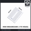 MB102 Breadboard 170 400 830 Holes Breadboard Donut Board Arduino Prototype Multi Color - MINI BREADBOARD 170 HOLES (WHITE)
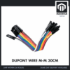 40pcs Dupont Wire 10cm 20cm 30cm for Breadboard DIY Experiment Jumper Wire Breadboard wire - DUPONT WIRE M-M 30CM
Optional — the two things that remove the hard parts
| Item | Price | Qty | |
|---|---|---|---|
 Soldering Service for Circuit Boards & Electronics - 5 Pins Soldering ServiceSOLSE05 Soldering Service for Circuit Boards & Electronics - 5 Pins Soldering ServiceSOLSE05 | RM0.80 | ||
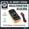 XL830L Digital Multimeter with backlight Portable Multimeter Electronics ProjectMULTIME XL830L Digital Multimeter with backlight Portable Multimeter Electronics ProjectMULTIME | RM25.95 |
The soldering service covers exactly five pins, which is exactly what the MAX3010x module needs; it is consultation-first, so message us on WhatsApp before adding it to your cart. Skip the multimeter if you already own one — it is listed because a single reading on SDA is the whole diagnosis in the I2C section below.
How do both sensors share one Arduino Uno?
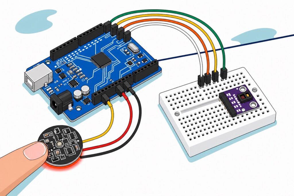
The pulse sensor is the easy half: its three leads each end in their own single-pin plug with a male pin, and the Uno‘s headers are female sockets, so they push straight in. The MAX3010x is the awkward half — five bare plated holes and a loose five-pin header in the bag, and once that header is on, the module has five male pins in one straight row while the four Uno pins it needs sit on two different headers. So it cannot plug into the Uno; it has to be wired. And a wire from a male module pin to a female Uno socket has to be female at one end and male at the other.
The 170-point mini breadboard settles that and does a second job. Its tie-points are female, so the module’s pins push into it and plain male-to-male jumpers carry the four connections on to the Uno’s female sockets — one gender at each end of every wire. It has no power rails — just tie-point rows either side of a centre groove — which is fine here, because each row is five holes joined by one metal clip underneath. Seat the module’s five pins in five adjacent rows and every pin owns four spare holes, so the row holding VIN becomes your 5 V junction: push the pulse sensor’s RED plug into a spare hole in it, run one M-M jumper from another to the Uno’s 5 V pin, and two parts share one supply pin.
| Part | Lead or pin | Goes to |
|---|---|---|
| Pulse sensor | YELLOW (S) | Uno A0 — straight into the socket |
| Pulse sensor | RED (+) | Spare hole in the breadboard row holding the module’s VIN |
| Pulse sensor | BLACK (−) | Uno GND on the POWER header — straight in |
| MAX3010x | VIN | Jumper from that row to Uno 5V |
| MAX3010x | GND | Jumper to the Uno GND pin beside D13 |
| MAX3010x | SCL | Jumper to Uno A5 |
| MAX3010x | SDA | Jumper to Uno A4 |
| MAX3010x | INT | Leave unconnected |
Both sensors sit on the Uno together because they occupy different pins — one analog input against the two-wire bus on A4 and A5 — which is why this is one build rather than two. Wire both once and swap sketches; each sketch below drives one sensor. (The pins marked SDA and SCL at the far left of the digital header are those same two pins, joined inside the board — use either pair.) VIN takes 5 V even though the die inside runs at 1.8 V, because the module carries its own regulator chain: VIN feeds a 3.3 V regulator whose output feeds a 1.8 V regulator for the chip. That is why the pin is VIN and not VCC, and why either of the Uno’s own rails works — 3.3 V or 5 V, and nothing above them. Everything past VIN is a small on-board regulator sized for logic voltages, so a 9 V or 12 V supply belongs on the Uno’s barrel jack, never on this pin.
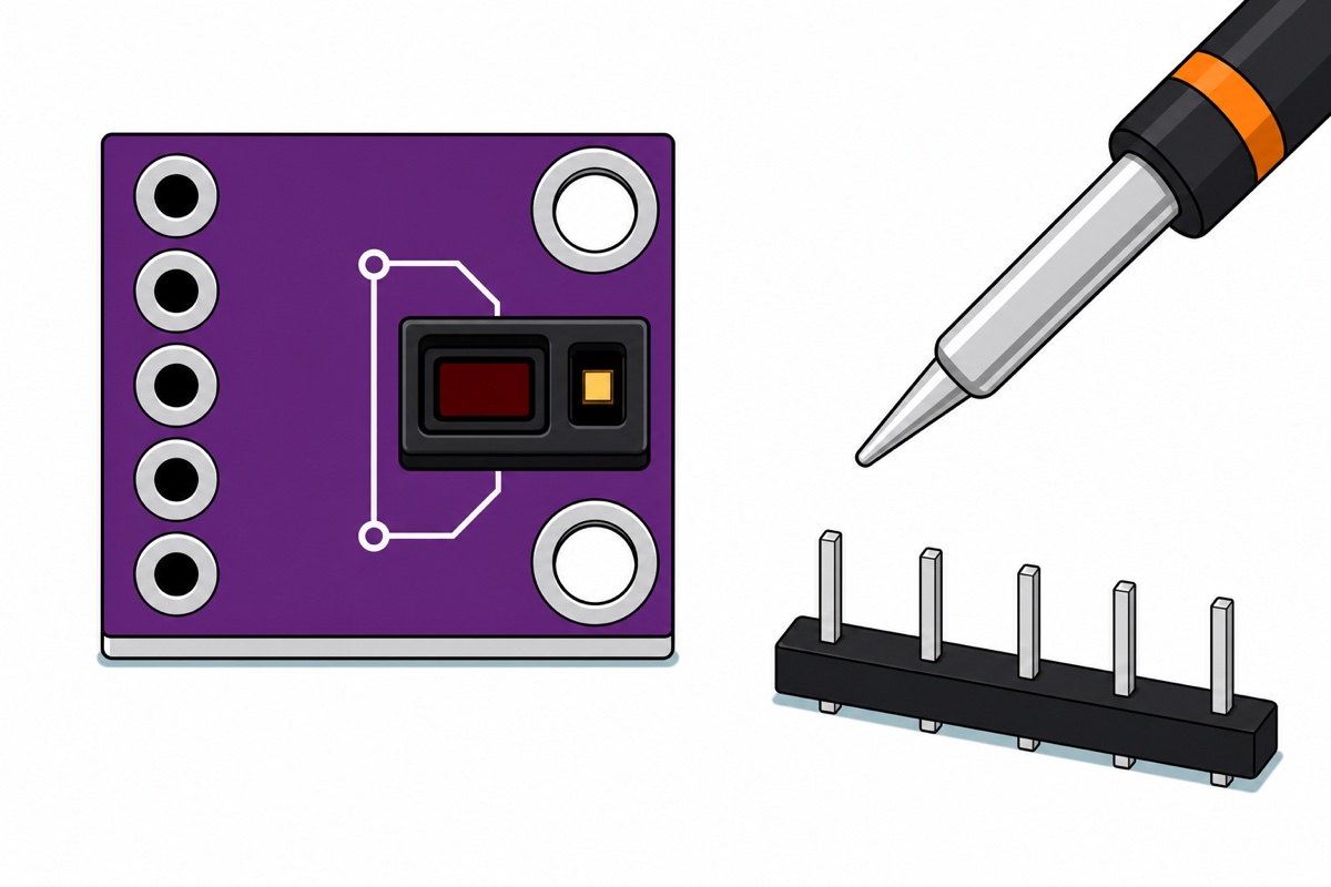
Soldering five pins is a fifteen-minute job — our header-soldering guide walks the row, and the trick is to stand the header in the breadboard first so the board sits level while you tack the first pin. The one real hazard: an iron tip near 350 °C scars before you feel it, so heat-proof surface, iron in its stand, window open for the flux smoke. Or the 5-pin soldering service covers these five. The motion is worth seeing:
Which MAX3010x is actually on your board?
The MAX3010x family shares one breakout layout, and this is where most projects stall. GY names an outline — same purple rectangle, same five pads, same printed legend — so the laminate tells you which board you hold, not which die is bonded inside that black optical package. You cannot settle it by looking, which is why Maxim put an identity register in the silicon.
Register 0xFF is that identity, read-only. Maxim’s MAX30105 datasheet register map lists 0xFF as PART_ID with the value 0x15, and SparkFun’s library — written for the MAX30102 and MAX30105 together — treats them as the same part; the older MAX30100 answers 0x11, the value the oxullo MAX30100 library hard-codes as its expected ID. The whole family answers at 7-bit address 0x57: the datasheet quotes a write address of 0xAE and a read address of 0xAF, and the low bit is the read/write flag, so 0xAE shifted right by one gives the 0x57 that Arduino’s Wire library expects.
This matters because both libraries refuse the wrong die and then blame your wiring for it. SparkFun’s begin() returns false if the ID is not 0x15; oxullo’s does the same against 0x11. Their own examples do test that boolean, but the message it buys you is SparkFun’s MAX30105 was not found. Please check wiring/power. or oxullo’s bare FAILED — both of which send you back to jumpers that were never the problem. Run this first:
// Which MAX3010x is actually on your breakout?
// Wiring: VIN -> Uno 5V, GND -> GND, SCL -> A5, SDA -> A4.
#include <Wire.h>

const uint8_t MAX3010X_ADDR   = 0x57;   // the whole family answers here
const uint8_t REG_REVISION_ID = 0xFE;
const uint8_t REG_PART_ID     = 0xFF;

bool readReg(uint8_t reg, uint8_t &value) {
  Wire.beginTransmission(MAX3010X_ADDR);
  Wire.write(reg);
  if (Wire.endTransmission(false) != 0) return false;   // repeated start, no stop
  if (Wire.requestFrom(MAX3010X_ADDR, (uint8_t)1) != 1) return false;
  value = Wire.read();
  return true;
}

void setup() {
  Serial.begin(115200);
  while (!Serial) { }
  Wire.begin();

  Serial.println(F("Scanning the I2C bus..."));
  uint8_t found = 0;
  for (uint8_t addr = 1; addr < 127; addr++) {
    Wire.beginTransmission(addr);
    if (Wire.endTransmission() == 0) {
      Serial.print(F("  device answered at 0x"));
      Serial.println(addr, HEX);
      found++;
    }
  }
  if (found == 0) {
    Serial.println(F("Nothing answered. Fix the bus before you install any library."));
    return;
  }

  uint8_t part = 0, rev = 0;
  if (!readReg(REG_PART_ID, part) || !readReg(REG_REVISION_ID, rev)) {
    Serial.println(F("0x57 answered the scan but the ID read failed."));
    return;
  }

  Serial.print(F("Part ID 0x"));
  Serial.print(part, HEX);
  Serial.print(F(", revision 0x"));
  Serial.println(rev, HEX);

  if (part == 0x11) {
    Serial.println(F("-> MAX30100. Install MAX30100lib by OXullo Intersecans."));
  } else if (part == 0x15) {
    Serial.println(F("-> MAX30102 or MAX30105. Install SparkFun MAX3010x."));
  } else {
    Serial.println(F("-> Not a MAX3010x part ID."));
  }
}

void loop() { }
Then install exactly one: MAX30100lib by OXullo Intersecans for 0x11, or the SparkFun MAX3010x Pulse and Proximity Sensor Library for 0x15. Type the full strings — a search for “MAX30” returns a screenful of entries, mostly forks whose class names will not match the example code you found. Our MPU6050 guide opens with the same bus scan.
Why does the I2C scan find nothing when every wire is right?
I2C is an open-drain bus, and that one fact explains a failure that swallows evenings. The ATmega328P’s own datasheet: “A high level is output when all TWI devices tri-state their outputs, allowing the pull-up resistors to pull the line high.” Nothing ever drives the line high; devices only pull it down or let go. So the high level is not the Uno’s 5 V — it is whatever rail the pull-ups are tied to.
On these breakouts the 4.7 kΩ pull-ups for SDA, SCL and INT sit on one of the module’s own internal rails, and which one depends on the revision. A widely reported batch, documented by Reed Paper, ties them to 1.8 V: “They are connected to the supply + 1.8V!!! If such a module is connected to a 5V logic of Arduino board – it will not be visible on the I2C bus because the logic levels are too low.”
The arithmetic shows it happening. Wire.begin() switches on the ATmega’s internal pull-ups on A4 and A5 — two lines inside the shipped core, digitalWrite(SDA, 1); digitalWrite(SCL, 1); — and the ATmega328P datasheet rates them at 20–50 kΩ. One of those from 5 V against the module’s 4.7 kΩ to 1.8 V leaves the line at a divider point: with the weakest 50 kΩ the 3.2 V difference across 54.7 kΩ pushes 58 µA, which lifts the node 0.28 V above 1.8 V, so it rests near 2.1 V; with the strongest 20 kΩ, about 2.4 V.
The receiving end settles it. That same datasheet puts the ATmega328P’s input-high threshold at 0.6 × VCC for ordinary I/O and a stricter 0.7 × VCC in its two-wire bus table — 3.0 V and 3.5 V on a 5 V Uno. A line at 2.1 V reaches neither, so the Uno reads a permanent low, nothing acknowledges, and a scan of the whole address space reports nothing: no error, no timeout, perfect wiring. Even the 3.3 V revision sits under that 3.5 V figure, which is why the same module works for one person and not another.
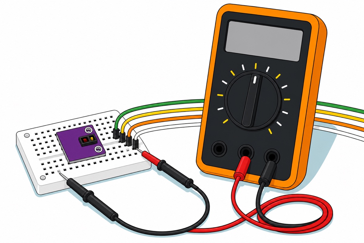
Which turns an evening into a measurement. Leave the scanner sketch loaded and running, so the Uno’s own pull-ups are switched on, then multimeter on DC volts, black probe on GND and red on the SDA jumper — our multimeter guide covers the dial. Three readings, three different answers. Close to 5 V means nothing on the module is pulling that line down at all — on a breakout that fits its own 4.7 kΩ pull-ups that points at the connection, not the levels: VIN unpowered, a dry joint, a jumper one row across. About 3.3 to 3.5 V is the good revision, pulled up to the module’s own 3.3 V rail — over the 0.6 × VCC figure but just under the 3.5 V the two-wire table wants, which is why boards like it mostly work and occasionally sulk; there a 3.3 V-logic host such as an ESP32 ends the argument (see our board comparison), and if a scan still finds nothing at that level, look at power and solder rather than logic. Around 2 V is the 1.8 V-rail revision, and there the only honest route is the documented modification that jumpers the pull-ups to 3.3 V — fine work under magnification, not a first solder job — because the ESP32 datasheet puts its own high threshold at 0.75 × 3.3 V, about 2.5 V, which 2 V does not clear either.
What you should not do is the popular fix of hanging an extra pull-up onto 5 V. The chip’s pins survive it — the datasheet rates “All Other Pins to GND”, which is where SDA and SCL live, at −0.3 V to +6.0 V — but the module’s own 4.7 kΩ resistors still sit on that internal rail, so a second 4.7 kΩ to 5 V lifts the line only to about 3.4 V while pushing roughly 340 µA backwards into a regulator output that can source but not sink. VDD’s absolute maximum is +2.2 V.
How do you get a waveform, and then a number?
The pulse sensor gives a result on the first upload, which is why it belongs in a project with a deadline. One thing before you touch it: the finger goes on the optical face, not the side you see in our product photo — that side carries the components and the three solder joints, so put a strip of insulating tape over it first. Damp fingertips across bare joints is how these little amplifiers die. Then load this, open Tools → Serial Plotter at 115200 and rest a fingertip on the round board with steady gentle pressure — firm enough not to slide, light enough not to squeeze the blood out:
// Pulse sensor: the raw PPG waveform, for the Arduino IDE Serial Plotter.
// Wiring on this module: YELLOW -> A0, RED -> 5V, BLACK -> GND. No library.
// This is a demonstration of an optical signal, not a medical measurement.

const uint8_t PPG_PIN = A0;
const unsigned long SAMPLE_US = 10000UL;   // 10 ms between samples = 100 Hz

void setup() {
  Serial.begin(115200);
}

void loop() {
  static unsigned long lastSample = 0;
  if (micros() - lastSample < SAMPLE_US) return;   // hold the sample rate steady
  lastSample += SAMPLE_US;

  Serial.println(analogRead(PPG_PIN));   // 0..1023; rests near 512 on a 5 V Uno
}
That 100 Hz is chosen, not guessed. A resting heart runs near 1 Hz, but the sharp upstroke and the small notch after each beat carry detail out to roughly 10 Hz, so 100 samples a second puts about ten points across each cycle of that fastest component — and it is cheap, since 115200 baud moves about 11 520 bytes a second against the roughly 600 those hundred short lines need.
Turning that trace into BPM needs one more idea. A fixed trigger fails because the resting level drifts with pressure and skin, so the sketch below tracks the highest and lowest readings of the last two seconds and triggers 60 % of the way up whatever swing your finger is producing. A 300 ms refractory window caps it at 200 BPM so one noisy edge cannot count twice; a gap over 2000 ms is treated as a restart. That memory has a cost worth expecting rather than debugging: just after each two-second reset the swing has to rebuild before a beat can cross, so one beat now and then goes uncounted and the next line prints about half your real rate. Read the run of agreeing numbers, never one line.
// Pulse sensor: turning that waveform into a BPM number.
// YELLOW -> A0, RED -> 5V, BLACK -> GND. No library. Serial Monitor at 115200.
// Demonstration of an optical principle. Not a medical measurement.

const uint8_t      PPG_PIN        = A0;
const unsigned long SAMPLE_US     = 10000UL;  // 100 samples per second
const unsigned long WINDOW_MS     = 2000UL;   // how long an extreme is remembered
const unsigned long REFRACTORY_MS = 300UL;    // ignore anything above 200 BPM
const unsigned long SLOWEST_MS    = 2000UL;   // below 30 BPM: treat as a restart
const int           MIN_SWING     = 20;       // counts; below this, no finger

int  hi = 0, lo = 1023;
unsigned long windowStart = 0;
unsigned long lastBeat = 0;
bool above = false;

void setup() {
  Serial.begin(115200);
}

void loop() {
  static unsigned long lastSample = 0;
  if (micros() - lastSample < SAMPLE_US) return;
  lastSample += SAMPLE_US;

  int reading = analogRead(PPG_PIN);
  unsigned long now = millis();

  if (reading > hi) hi = reading;
  if (reading < lo) lo = reading;

  // The trigger level is not a constant. It sits 60 % of the way up whatever
  // swing this finger is producing right now, so it survives a drifting DC level.
  int span = hi - lo;
  int threshold = lo + (span * 3) / 5;

  if (span >= MIN_SWING && reading > threshold && !above &&
      now - lastBeat > REFRACTORY_MS) {
    above = true;
    unsigned long interval = now - lastBeat;
    bool firstEver = (lastBeat == 0);   // nothing to measure the first one against
    lastBeat = now;
    if (!firstEver && interval < SLOWEST_MS) {
      Serial.print(F("beat: "));
      Serial.print(interval);
      Serial.print(F(" ms since the last one -> "));
      Serial.print(60000UL / interval);
      Serial.println(F(" BPM (demo only)"));
    }
  }
  if (reading < threshold) above = false;   // arm the next rising crossing

  // Forget old extremes, or one twitch sets the bar for the rest of the session.
  if (now - windowStart > WINDOW_MS) {
    windowStart = now;
    hi = reading;
    lo = reading;
  }
}
Finger pressure is the one part nobody gets right from a written description, so it is worth watching:
Common mistakes we see from real customers
Installing a library before checking the part ID. The sketch compiles, uploads, and announces that the sensor was not found — check wiring and power. So the next hour goes on wiring that was already correct. begin() read register 0xFF, disliked the answer, and had no way to say so. Read the ID first.
Re-checking the wiring for an hour when the wiring was never the problem. A silent scan feels exactly like a loose jumper, so people re-seat everything repeatedly. One meter reading settles it, and it also catches the other silent cause: a pad that looks soldered but hides a cold joint.
Chasing a stable BPM while the finger is moving. The trace is a light level, so a shifting finger is a real signal and genuinely indistinguishable from a beat. Rest your hand on the table and read numbers only once the plotter looks regular.
Building a project around an SpO₂ percentage. Readings that look plausible are the trap. Build the demonstration around heart rate and the waveform, treat any oxygen figure as an unvalidated experiment and say so — the stronger science-fair entry anyway. Our RBT project ideas page has more builds that judge well.
FAQ
Can a MAX30102 module measure my blood oxygen accurately?
No. It is a hobby breakout, not a medical device, and nothing it prints should be used to judge anyone’s health. A defensible SpO₂ figure needs a calibrated red-to-infrared absorption ratio validated against certified equipment. Demonstrate heart rate and the raw waveform instead.
Why does my I2C scanner find nothing when the wiring is correct?
I2C never drives the line high — pull-up resistors do, so the high level is whatever rail they sit on. On the low-rail revision of this breakout the bus idles near 2 V, and a 5 V Arduino Uno needs at least 3.0 V to call anything high, so it reads a permanent low and reports nothing. Measure SDA against GND to confirm.
Which Arduino library do I install for this sensor?
Read register 0xFF first. 0x11 means MAX30100 — install MAX30100lib by OXullo Intersecans. 0x15 means MAX30102 or MAX30105 — install the SparkFun MAX3010x Pulse and Proximity Sensor Library. Both reject the wrong die and report it as a wiring fault.
Does the MAX3010x module come with its header soldered?
No — it ships with five bare plated holes and a loose five-pin header strip. Solder the five joints yourself, or add our 5-pin soldering service, which is consultation-first: message us before you add it to the cart.
Can I run both sensors on one Arduino Uno at the same time?
Yes. The pulse sensor uses one analog input and the MAX3010x uses A4 and A5, so they never collide. Share 5 V and GND through the mini breadboard and both run off one USB cable.
Last updated August 2026. Stuck? Chat with us on WhatsApp.
