

Tutorials
WS2812 RGB LEDs with Arduino: Wiring + First Animations
May
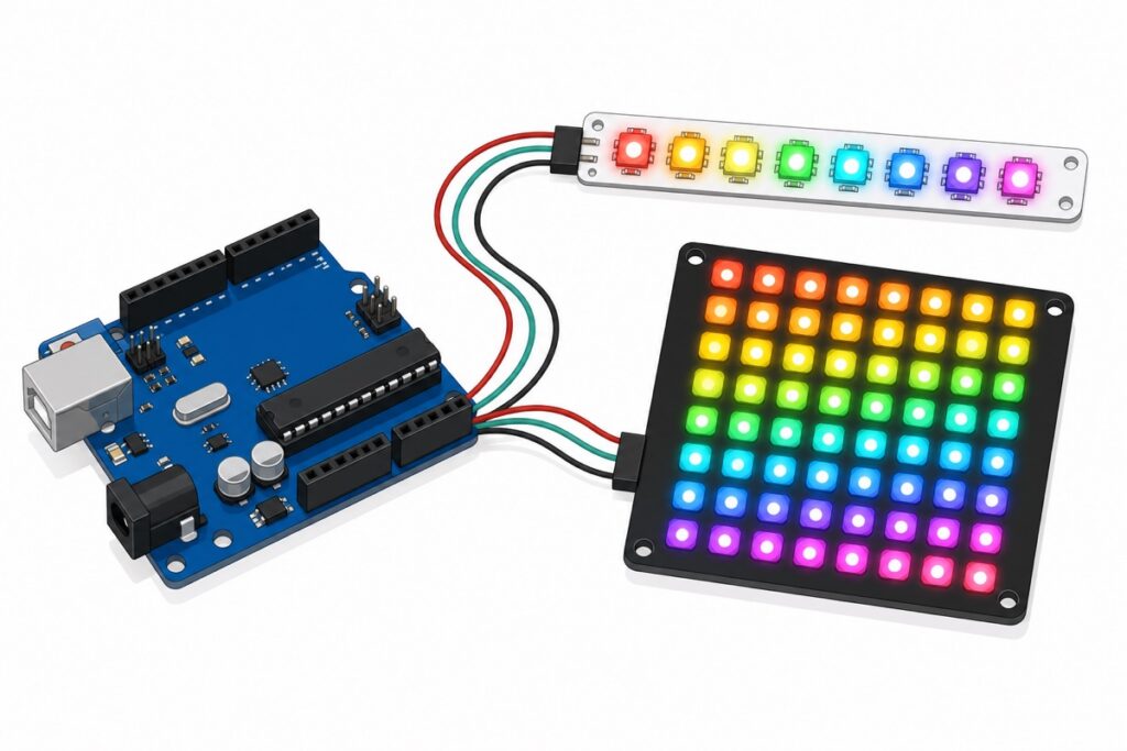
WS2812 RGB LEDs need only three wires to an Arduino Uno — 5V, GND and one data pin — plus the free Adafruit NeoPixel library to run every colour and animation from a single sketch. The one rule that keeps everything alive: budget your power, because each LED can draw up to 60mA at full white.
What makes WS2812 LEDs different from ordinary RGB LEDs?
A WS2812 packs a red, green and blue LED plus a tiny driver chip into one 5050 package, so each pixel understands digital data instead of needing three PWM wires of its own. Colour data goes down one pin; every pixel keeps its own 24-bit colour and passes the rest along the chain — one Arduino pin drives the whole matrix.
We will use two boards in this tutorial: the 8-LED WS2812 stick (slim white PCB, pads marked GND / IN / VCC on one end and an OUT set on the other) and the 8×8 WS2812 matrix (black square PCB, 64 LEDs, mounting holes). The same wiring and code drive both — only the LED count and power budget change.
Parts list
 Arduino Uno Compatible SMD UNO R3 with Type B Cable - ATMEGA328P with CH340G-Microcontroller Project
 RGB LED Bar WS2812 5050 LED 8 Bit Individual Control LED RGB Stick Programmable
 RGB Led Matrix Development Board 24 Bits Colour WS2812 5050 LED 4 16 25 64 - WS2812 RGB DISPLAY (64)
How do you wire the 8-LED stick to the Arduino Uno?
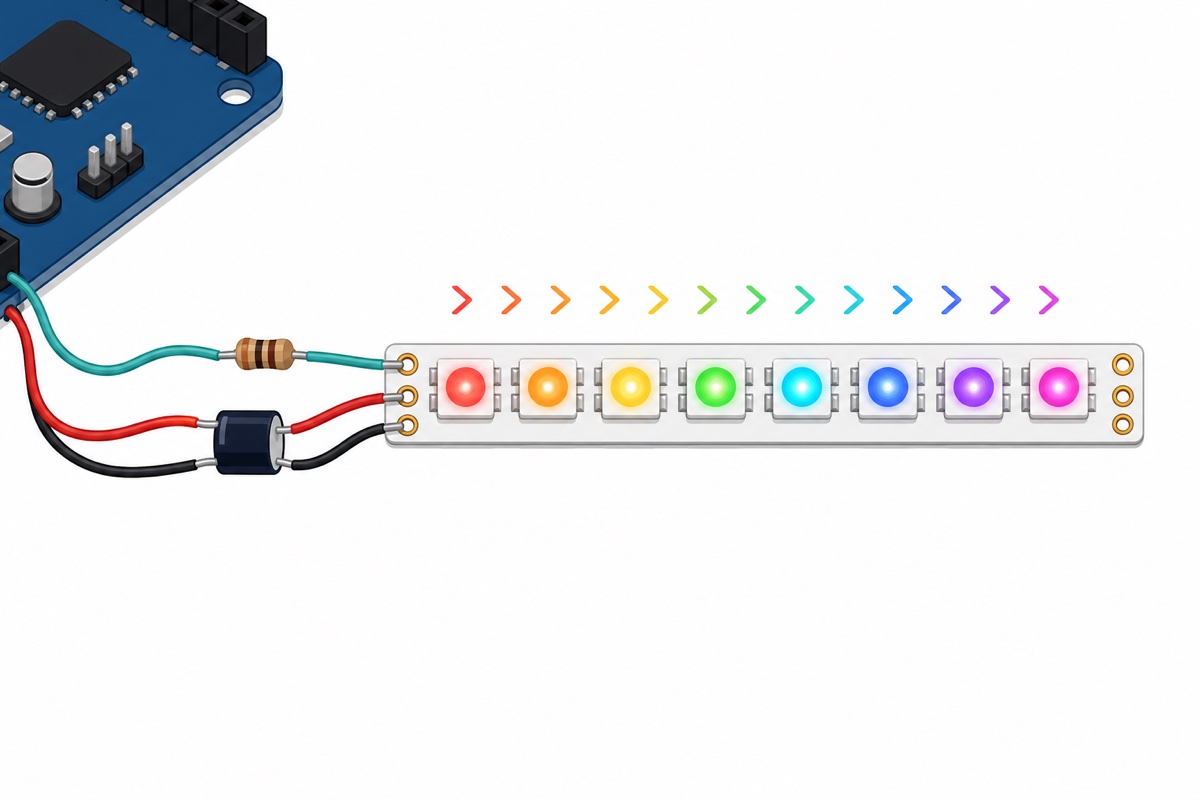
The WS2812 stick has an IN end and an OUT end, and the direction matters: data only flows IN → OUT, so the Arduino must connect to the IN-end pads. Wire the OUT end instead and the sketch runs happily while the LEDs stay dark — the number-one first-timer trap.
| WS2812 stick (IN end) | Arduino Uno | Note |
|---|---|---|
| GND | GND | Connect ground first |
| VCC | 5V | Fine for the 8-LED stick at low brightness |
| IN (data in) | D6 | Through a 300–500Ω resistor, placed near the stick |
Two extras come straight from Adafruit’s NeoPixel best practices: a 300–500Ω resistor in the data line to protect the first pixel from signal spikes, and a large capacitor (500–1000µF, 6.3V or higher) across VCC and GND to absorb power-on inrush. Plenty of small desk demos skip both and get away with it — but the parts cost less than a teh tarik and turn a demo into a build that survives a hundred plug-ins. The third rule is free: connect GND first, disconnect it last.
How much current do WS2812 LEDs really draw?
Each WS2812 pixel draws up to 60mA at full-brightness white, and around 20mA in typical mixed-colour use. Multiply by LED count and the two boards live in different worlds:
| Board | LEDs | Worst case (full white, max brightness) | Typical (mixed colours) | USB / Uno 5V pin? |
|---|---|---|---|---|
| 8-LED stick | 8 | ~480mA | ~160mA | Borderline — OK at low brightness |
| 8×8 matrix | 64 | ~3.8A | ~1.3A | No — external 5V supply required (brief low-brightness test only) |
A USB port budgets about 500mA for the whole board, so the stick at full white would eat nearly all of it. That is why every sketch below calls setBrightness(40) — at 40 of 255, the stick’s worst case drops to roughly 80mA — comfortably inside USB territory, and still plenty bright indoors.
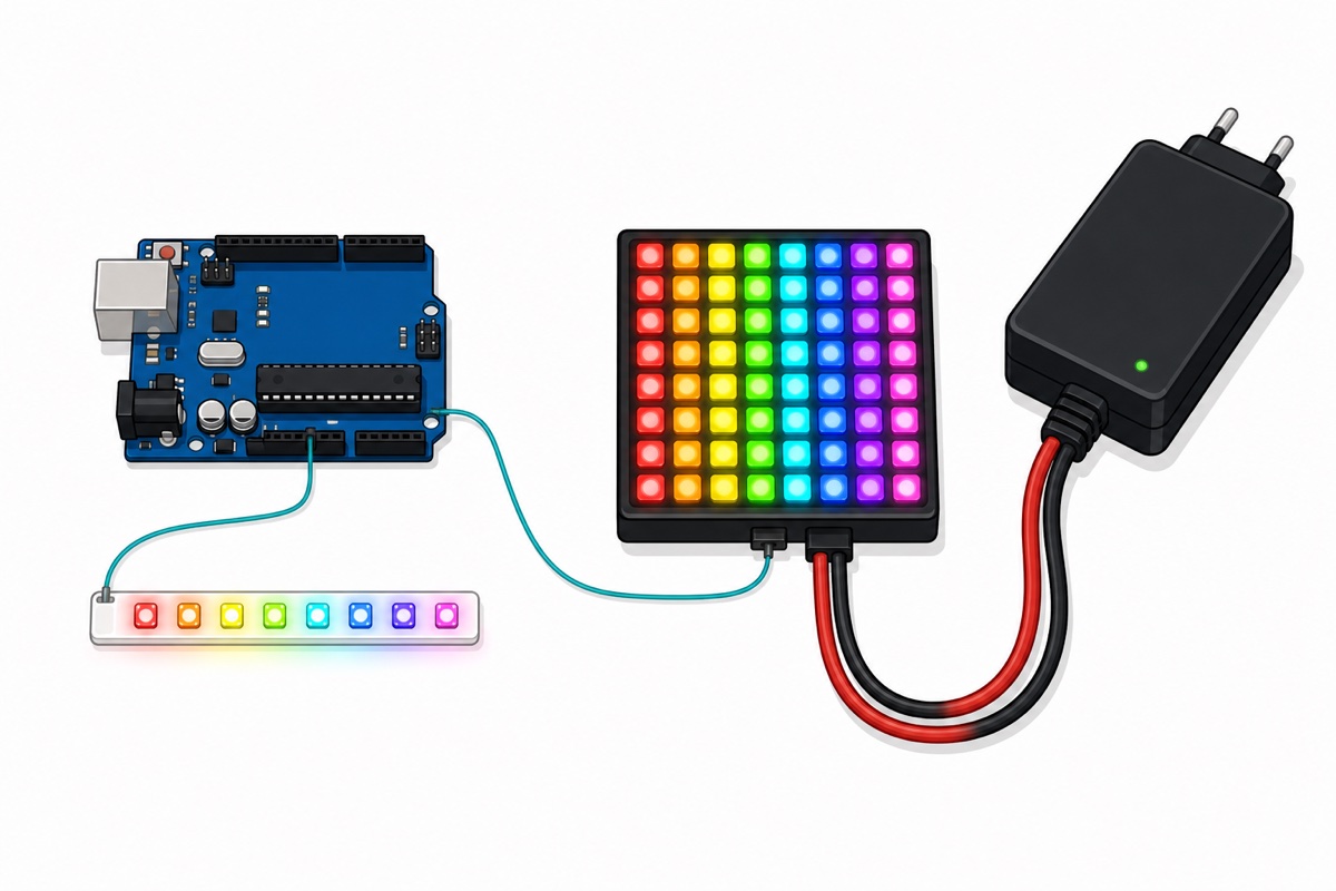
The 8×8 matrix is a different animal: 3.8A at full white must never come through the Uno’s 5V pin or the USB port. Feed it from an external 5V supply (a 5A rating gives headroom) wired directly to the matrix VCC and GND pads, then run just two wires to the Uno: data, plus a shared GND between supply, matrix and Uno — without the common ground the data has no reference and the matrix shows garbage. Building your 5V rail from a higher-voltage source? Our LM2596 buck converter guide shows how; for battery-powered builds, start with the TP4056 18650 charging guide.
How do you install the library and light your first LEDs?
The Adafruit NeoPixel library is the beginner-friendly standard: in the Arduino IDE open Tools → Manage Libraries, search for “Adafruit NeoPixel” and click Install. (FastLED is the other big WS2812 library — more powerful, steeper learning curve.) Then upload this first-light sketch with the stick wired to D6:
#include <Adafruit_NeoPixel.h>

#define LED_PIN    6    // Uno pin wired to the stick's IN pad
#define LED_COUNT  8    // 8 for the stick, 64 for the matrix

Adafruit_NeoPixel pixels(LED_COUNT, LED_PIN, NEO_GRB + NEO_KHZ800);

void setup() {
  pixels.begin();            // initialise the WS2812 driver
  pixels.setBrightness(40);  // low brightness = safe on USB power
  pixels.clear();

  // Light every pixel teal, one at a time
  for (int i = 0; i < LED_COUNT; i++) {
    pixels.setPixelColor(i, pixels.Color(0, 150, 120));
    pixels.show();           // push the colours to the LEDs
    delay(150);
  }
}

void loop() {
  // First light only - nothing to repeat
}
If all eight pixels march on in teal, wiring, library and power are all correct. If nothing lights, check the common mistakes section before touching the code.
Prefer to watch it once before building? This Core Electronics walkthrough covers the same wiring and library setup:
How do you make a rainbow and chase animation?
The Adafruit NeoPixel library’s HSV colour helper makes a smooth rainbow easy: sweep the hue and let ColorHSV() do the maths. This sketch cycles a full rainbow across the strip, then runs a teal theatre-chase:
#include <Adafruit_NeoPixel.h>

#define LED_PIN    6
#define LED_COUNT  8   // set to 64 for the matrix (external 5V supply required)

Adafruit_NeoPixel pixels(LED_COUNT, LED_PIN, NEO_GRB + NEO_KHZ800);

void setup() {
  pixels.begin();
  pixels.setBrightness(40);  // raise this only on a proper supply
}

void loop() {
  rainbowCycle(20);
  theaterChase(pixels.Color(0, 150, 120), 60);
}

// Slide the full colour wheel across the strip
void rainbowCycle(int wait) {
  for (long firstHue = 0; firstHue < 65536; firstHue += 512) {
    for (int i = 0; i < LED_COUNT; i++) {
      long hue = firstHue + (i * 65536L / LED_COUNT);
      pixels.setPixelColor(i, pixels.gamma32(pixels.ColorHSV(hue)));
    }
    pixels.show();
    delay(wait);
  }
}

// Every third pixel marches along the strip
void theaterChase(uint32_t color, int wait) {
  for (int cycle = 0; cycle < 10; cycle++) {
    for (int offset = 0; offset < 3; offset++) {
      pixels.clear();
      for (int i = offset; i < LED_COUNT; i += 3) {
        pixels.setPixelColor(i, color);
      }
      pixels.show();
      delay(wait);
    }
  }
}
To run it on the 8×8 matrix, change LED_COUNT to 64 and wire the external supply as described above — the matrix is addressed as one long 64-pixel strip, so the rainbow runs through it row by row. Keep setBrightness(40) until the external supply is connected.
Want to see the 8×8 matrix wired up and running before you try it yourself? This Mario’s Ideas video connects the matrix to an Arduino and drives it with the FastLED library:
Can a 3.3V board like the ESP32 drive WS2812 LEDs?
The WS2812’s classic datasheet wants a data-high level of at least 0.7 × the supply voltage — 3.5V when the LEDs run on 5V — while an ESP32 pin only swings to 3.3V. It often works anyway (newer chip revisions are more tolerant), but it is marginal: wiring that behaves on the desk can glitch once wires lengthen or the supply sags. A level shifter such as the 74AHCT125 is the textbook fix. For this tutorial the Uno is the honest choice — its 5V logic matches the LEDs natively. Choosing a board for your next project? See our ESP32 vs ESP8266 vs Arduino Uno comparison.
Common mistakes we see from real customers
Wiring the Arduino to the OUT end. The sketch uploads fine, nothing lights, and the code gets blamed before anyone re-reads the pads. Check the silkscreen: the Uno’s data wire goes to IN.
Running the matrix at full white from the Uno’s 5V pin. The Uno browns out and resets, or the USB port shuts down. The 64-LED matrix always gets its own 5V supply at high brightness.
Forgetting the shared ground with an external supply. Power the matrix separately but skip the GND wire back to the Uno, and the LEDs flash random colours or freeze. Data needs a common ground reference.
Missing pixels.begin() or pixels.show(). begin() initialises the pin; show() transmits the colours. Set colours without calling show() and nothing visibly changes.
Testing with brightness at 255 on USB power. A full-white flash of even the 8-LED stick can dip the USB rail enough to disconnect the serial port mid-upload. Start at 40; raise it later on proper power.
FAQ
Can I power the 8×8 matrix from the Arduino’s 5V pin?
Only for a cautious first test at very low brightness (setBrightness(10), a few pixels). Anything more needs an external 5V supply wired straight to the matrix VCC/GND pads, with ground shared with the Uno. At full white the matrix can pull ~3.8A — far beyond what the Uno or a USB port can deliver.
How many WS2812 LEDs can one Arduino Uno control?
The library needs 3 bytes of RAM per pixel, and the Uno has 2KB of SRAM, so roughly 500 LEDs is the practical ceiling before memory runs out — the data line itself can drive long chains. Power becomes the real limit long before RAM does.
Can I chain the stick and the matrix together?
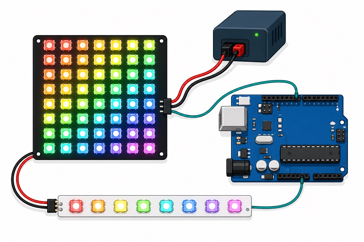
Yes — connect the stick’s OUT pads to the matrix’s IN pads and set LED_COUNT to 72. They behave as one long strip: pixels 0–7 are the stick, 8–71 are the matrix. Power budgets add up too, so the external-supply rule for the matrix still applies.
Why do my LEDs flicker or show wrong colours?
Usually a data-signal problem: no resistor on the data line, a long or thin data wire, a missing shared ground, or a sagging power supply. Shorten the data wire, add the 300–500Ω resistor near the first pixel, and confirm every ground is connected together.
WS2812 vs WS2812B — what is the difference?
The B revision is the improved version of the original WS2812 — simpler 4-pin package and better reliability. Boards sold today, including the stick and matrix here, use the B revision. Wiring, libraries and code are identical, which is why everyone just says “WS2812”.
Last updated August 2026. Stuck? Chat with us on WhatsApp.
