

Tutorials
Arduino Solar Panel + TP4056 + 18650: What Runs at Night
Aug
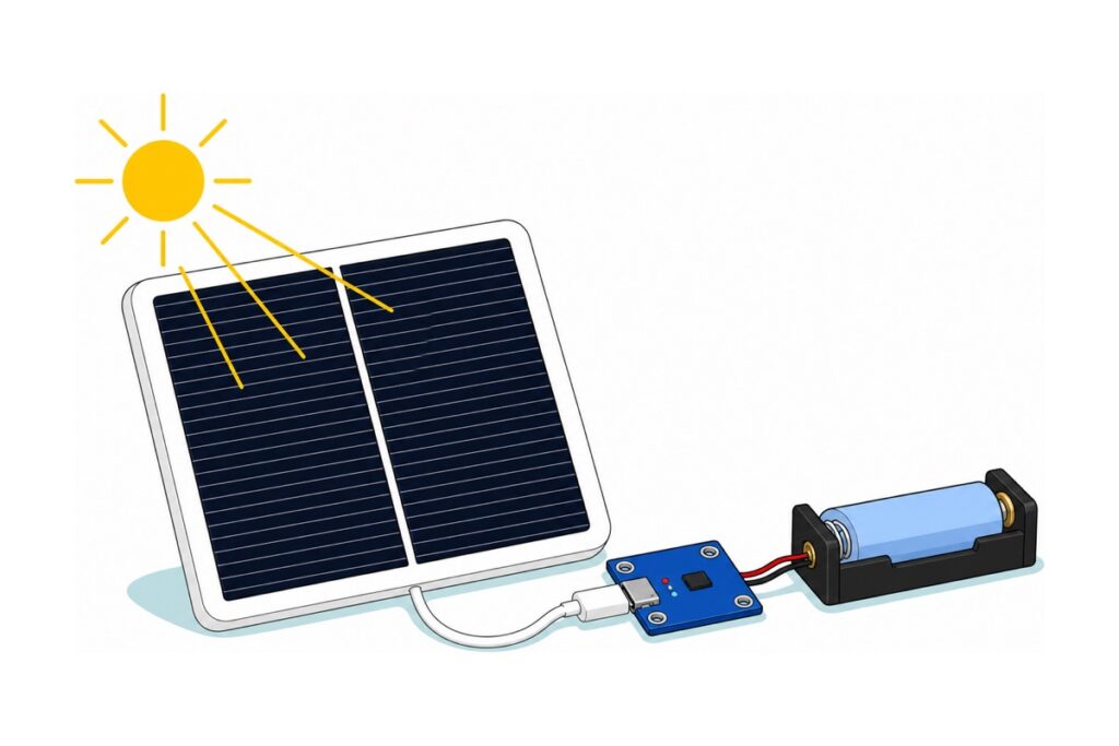
A solar panel does not run your Arduino — it refills a battery, and the battery runs your Arduino. Our 6 W 5 V panel plugs straight into a TP4056 Type-C charger, which fills one 18650, which feeds a boost module holding a steady 5 V. Whether that survives the night is arithmetic, and this guide does it with you.
What do you actually need to solar-power an Arduino or ESP32?
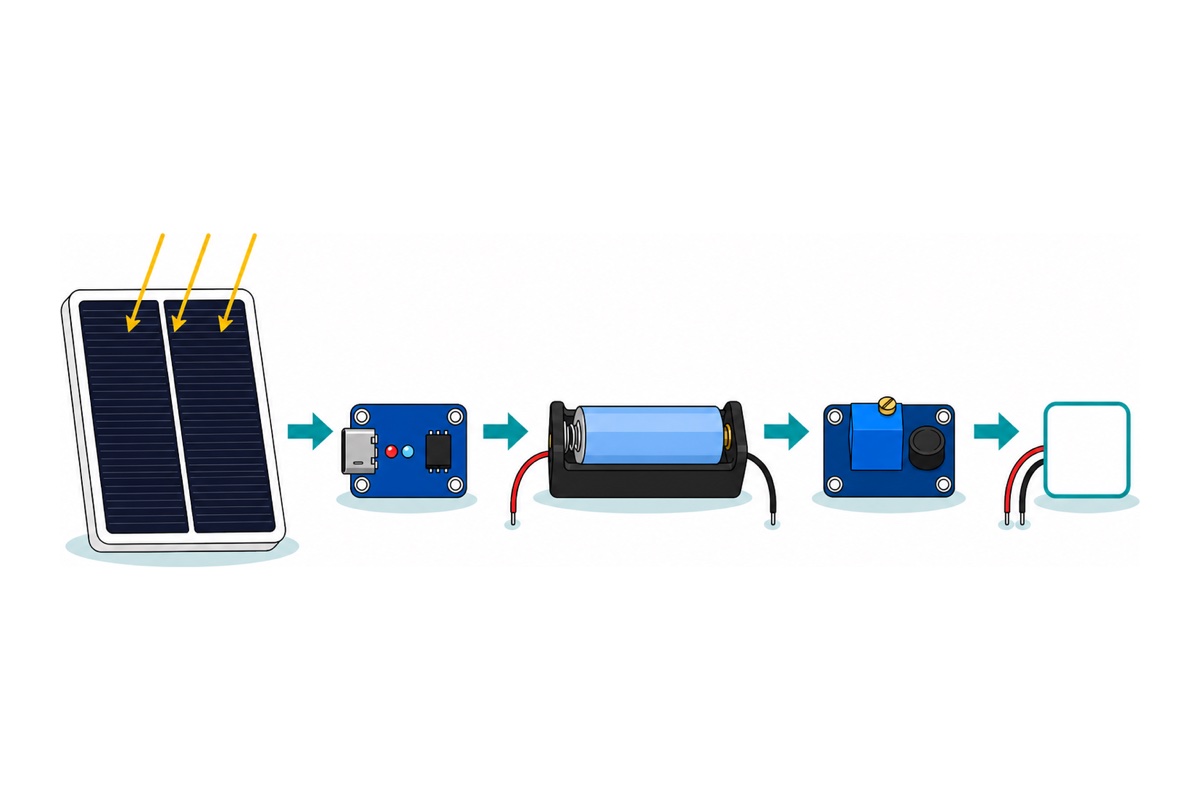
A solar build is four stages between the sun and your project: panel → charger → cell → boost converter. Panel output swings with the clouds, the cell buffers that, and the boost turns its falling 4.2–3.0 V into the steady 5 V a Uno or ESP32 expects.
Parts list — solar charging chain for a 5 V project
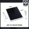 Monocrystalline Cells Solar Panel 5V 6V 3W 6W 10W 15W Mono Solar Energy - 6W 5V SOLAR PANEL
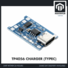 TP4056 18650 Battery Charger Module Lithium Ion Battery Li-ion Battery Charger Type C Micro USB - TP4056 CHARGER (TYPEC)
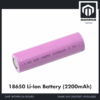 3.7V 18650 Battery Rechargeable Li-Ion Battery 1200mAh 2200mAh 3200mAh Flat Top - 18650 Li-Ion Battery (2200mAh)
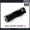 18650 Battery Holder 1/2/3/4 Slot 3.7V Battery Cell Housing Battery Case Battery Casing - 18650 BATTERY HOLDER (1)
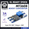 MT3608 Adjustable Step-up Convertor Boost Converter Switching Boost Converter for Arduino Project
 40pcs Dupont Wire 10cm 20cm 30cm for Breadboard DIY Experiment Jumper Wire Breadboard wire - DUPONT WIRE M-M 20CM
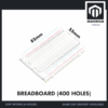 MB102 Breadboard 170 400 830 Holes Breadboard Donut Board Arduino Prototype Multi Color - BREADBOARD (400 HOLES)
Parts list
| Item | Price | Qty | |
|---|---|---|---|
 Soldering Service for Circuit Boards & Electronics - 10 Pins Soldering ServiceSOLSE10 Soldering Service for Circuit Boards & Electronics - 10 Pins Soldering ServiceSOLSE10 | RM1.40 |
This chain needs eight soldered joints: two at the charger's B pads, four for the charger-to-boost link, two at the boost output. Add the 10-pin soldering service and we make them for you — message us on WhatsApp with your build so we solder the right pads.
The 6 W 5 V panel ends in a USB Type-C male plug and the Type-C TP4056 presents a Type-C female socket, so the input side needs no adapter and no solder — pick this charger over the micro-USB version. The panel hardwires its cells to the plug’s power pins, so there is no negotiation chip to satisfy.
The 18650 charger-plus-boost module puts a Type-C input, a 4056-class charger, protection and a 2 A 5 V boost on one PCB — two solder joints instead of eight. The parts list keeps the stages separate so each can be measured.
How much power does a 6 W panel really put into an 18650?
The 6 W 5 V panel can deliver about 1.2 A in full sun — 6 W ÷ 5 V. The TP4056 cannot take all of it: it is a 1 A charger by design, programmed by one resistor to a maximum of 1000 mA. The chain’s ceiling is therefore 1 A, which a 6 W panel already saturates: a 10 W or 15 W panel offers 2 A or 3 A, the charger still takes 1 A, and the surplus never leaves the panel.
Heat lowers the real figure further, because the TP4056 is a linear charger: it does not convert the surplus voltage, it burns it. At 5 V in and a 3.7 V cell drawing 1 A, (5 − 3.7) × 1 = 1.3 W becomes heat in a package rated for 2 W at 50 °C/W to ambient — 1.3 × 50 = 65 °C above the surrounding air. The chip holds its own die at 125 °C by trimming charge current, so inside a closed box on a Malaysian afternoon it charges well under 1 A.
Filling an empty cell therefore takes 2200 mAh ÷ 1000 mA ≈ 2.2 hours at the ceiling, plus the tail where the charger holds 4.2 V and lets current fade to termination. Kuala Lumpur receives about 4.8 kWh/m² a day averaged over the year in NASA’s POWER climatology, and 4.2 in the dullest month; one “peak sun hour” is 1 kWh/m², so plan on about 4.5 peak sun hours for a fixed panel — a clear day offers about 4.5 Ah against a cell that holds 2.2 Ah, while a grey monsoon day at a quarter of that light banks only 1.3 Ah — less than one cell, and the grey run is what sizing has to survive.
A 12 V CCTV or alarm system belongs in a different lane. A 12 V 7 Ah battery holds 84 Wh; a 6 W panel gathers at most about 27 Wh over a 4.5-hour solar day before losses, and a TP4056 regulating to 4.2 V cannot charge such a pack at all. Those need a larger panel, a multi-cell 2S/3S/4S CN3304 board, and a buck converter on the way back down.
The same sums, measured on a bench:
What actually runs through the night?
One 18650 cell holds 2200 mAh at 3.7 V nominal — 8.1 Wh. A boost converter conserves energy, not current: it trades amps for volts, and it takes a cut on the way. The MT3608 datasheet headlines “up to 97 %”, which is its best case at a gentle step-up; budget 90 % for lifting a sagging 3.7 V cell to 5 V. That leaves 7.3 Wh, and 7.3 Wh ÷ 5 V ≈ 1450 mAh at the 5 V rail. A 2200 mAh cell is not 2200 mAh of 5 V supply, and that gap is where most solar projects die.
Malaysian nights run close to 12 hours all year, so spending 1450 mAh across one is 120 mA continuous — and arriving at dawn empty. Empty is a hard stop: the module’s DW01 protection chip disconnects the cell at its over-discharge threshold, then re-trips as the rested cell rebounds, which reads as a faulty board. Design for half a cell a night.
| Load on the 5 V rail | Typical current | Over a 12-hour night | Share of one cell (1450 mAh at 5 V) |
|---|---|---|---|
| Arduino Uno, sketch running | ~45 mA | 540 mAh | 37 % |
| ESP32 DevKit, Wi-Fi connected and idle | ~100 mA | 1200 mAh | 83 % |
| ESP32 DevKit, 10 s awake every 10 min | ~11.5 mA | 138 mAh | 10 % |
| Bare ESP32 module in deep sleep | 10 µA | 0.12 mAh | ~0 % |
The duty-cycled row is an average, not a mode: (10 s × 100 mA + 590 s × 10 mA) ÷ 600 s = 11.5 mA. And that 10 mA floor is the board, not the chip. Espressif specifies 10 µA in deep sleep and 95–100 mA receiving Wi-Fi, but a DevKit also carries a regulator whose quiescent current alone is 5 mA typical, a power LED and a USB-serial chip — none of which your sketch can switch off. Measure your own with a multimeter in series or an INA3221 monitor.
How do you wire the chain, and what has to be soldered?
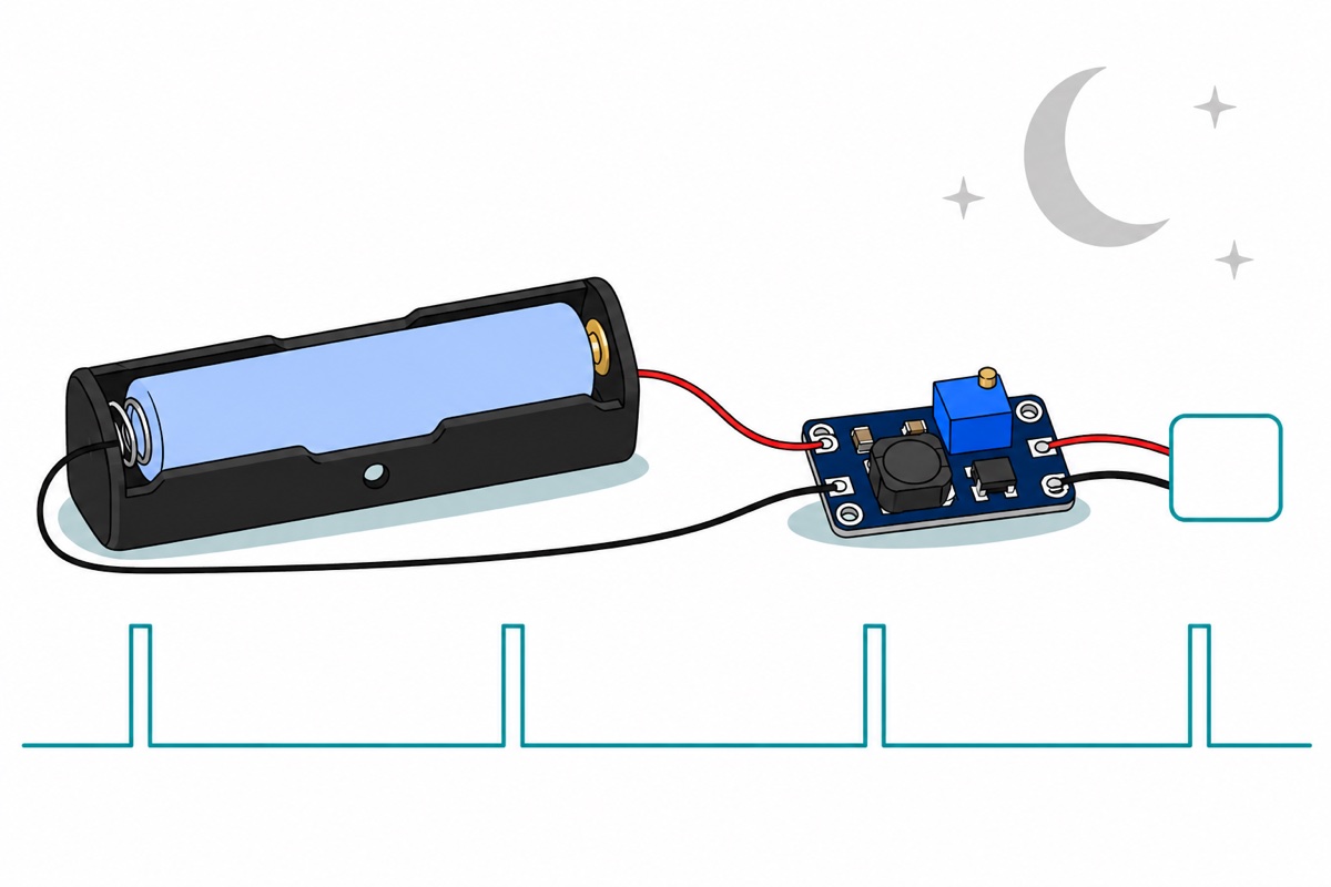
The TP4056’s four pads are where this build goes badly wrong: the cell goes to B+/B− and everything else hangs off OUT+/OUT−, because the protection MOSFETs sit between those pairs. Our TP4056 charging guide covers that pad discipline and the LED states in full.
| From | To | Why |
|---|---|---|
| Panel USB-C plug | TP4056C Type-C socket | Plugs in; no adapter, no solder |
| Holder red lead | TP4056 B+ | Cell positive, inside the protection |
| Holder black lead | TP4056 B− | Cell negative, inside the protection |
| TP4056 OUT+ / OUT− | MT3608 VIN+ / VIN− | Protected output feeds the boost |
| MT3608 VOUT+ | Uno 5V pin, or ESP32 5V/VIN | Regulated 5 V into the board |
| MT3608 VOUT− | Board GND | Shared return for the whole chain |
All eight joints are wire-to-pad on bare through-holes; the soldering guide covers technique. Cut four male-to-male jumpers in half: two halves are soldered at both ends to carry OUT+/OUT− into VIN+/VIN−, and two more go to VOUT, where the surviving male pins push into an Uno’s female headers or into the breadboard’s rails beside a male-pinned ESP32 DevKit.
The MT3608’s blue cube is a multi-turn trimmer, so many turns pass before the output moves at all: keep turning while a multimeter reads VOUT, stop at 5.0–5.2 V, then connect the load. Left at its factory setting it can sit far above 5 V, and an Arduino’s 5V pin has no regulator behind it to save you. Feed the board from the boost or from USB, never both: an Uno’s 5V pin is the USB socket’s own rail, so the boost would push current into your laptop’s port.
How do you make an ESP32 sleep between jobs?
The ESP32’s deep sleep is not a pause: it powers down the CPU and radio, then restarts the sketch at setup() on waking — which is why the counter below lives in RTC memory rather than an ordinary variable.
// Solar-friendly duty cycle for an ESP32: wake, do the job, switch off.
// Deep sleep is what makes a 6 W panel enough - the board spends the
// night switched off instead of idling on Wi-Fi all night long.

const int WORK_SECONDS  = 10;   // seconds awake per cycle
const int SLEEP_MINUTES = 10;   // minutes asleep between wakes

// Ordinary variables are wiped by deep sleep; RTC memory survives it.
RTC_DATA_ATTR unsigned int wakeCount = 0;

void doTheWork() {
  // Your real job goes here: read a sensor, send a reading, blink an LED.
  // Keep it short - every extra second awake is battery you spend.
  for (int s = 0; s < WORK_SECONDS; s++) {
    Serial.print("working... ");
    Serial.println(s + 1);
    delay(1000);
  }
}

void setup() {
  Serial.begin(115200);
  delay(200);                   // let the USB serial port settle
  wakeCount++;
  Serial.print("Wake #");
  Serial.println(wakeCount);

  doTheWork();

  // esp_sleep_enable_timer_wakeup() counts in MICROseconds, so a
  // 10-minute nap is 10 * 60 * 1000000. Do the maths in 64-bit: plain
  // int arithmetic overflows once the nap passes about 35 minutes.
  uint64_t sleepMicros = (uint64_t)SLEEP_MINUTES * 60ULL * 1000000ULL;
  esp_sleep_enable_timer_wakeup(sleepMicros);

  Serial.print("Sleeping for minutes: ");
  Serial.println(SLEEP_MINUTES);
  Serial.flush();               // finish printing before the UART powers down
  esp_deep_sleep_start();       // nothing after this line ever runs
}

void loop() {
  // Never reached. Waking from deep sleep is a reboot: the chip starts
  // again at setup(), which is exactly why wakeCount lives in RTC memory.
}
It compiles to 276,128 bytes, about 21 % of the DevKit’s app space. An Arduino Uno has no equivalent win — its ATmega328P can sleep, but the board’s power LED and USB-serial chip keep drawing regardless — so for solar, duty-cycling an ESP32 beats starving a Uno. The dual-18650 shield in our ESP32 power guide is a tidy indoor alternative, but it charges through micro-USB, so this panel’s Type-C plug cannot feed it.
Is the solar panel waterproof — and what about everything else?
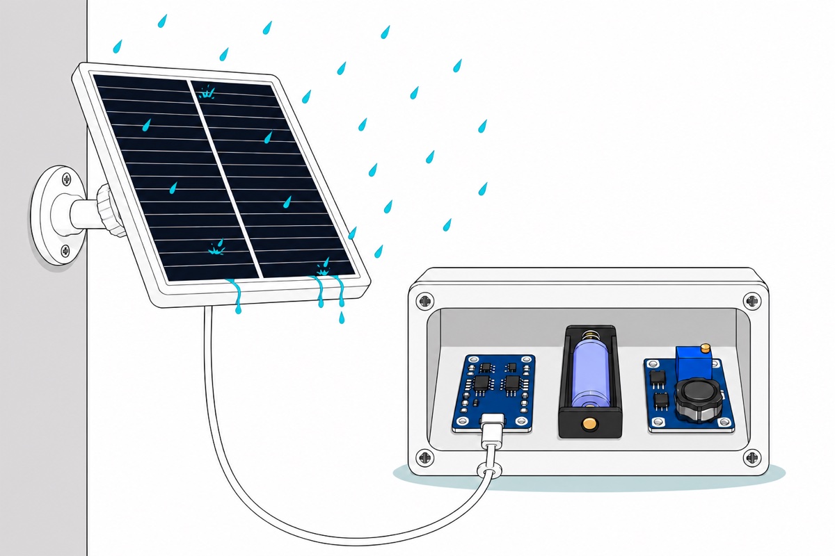
The 6 W monocrystalline solar panel is the only outdoor part of this chain. Its cells sit behind a hard laminated front sealed into a moulded frame with no openings on the face, and it ships with an outdoor CCTV-style swivel bracket. Treat it as rain-tolerant rather than submersible — mount it tilted so water sheds and dirt washes off, cable exit pointing down.
Nothing after the plug is weatherproof. The USB-C junction, charger, boost, cell and board all need an enclosure, with the cable entering from below through a drip loop so water runs off the cable instead of following it in. Keep that box in shade, not tucked behind the panel: a lithium cell baking in a sealed black box in direct sun is the one genuinely dangerous part of this build, because charging a hot 18650 degrades it quickly and, in the extreme, is how cells vent.
Common mistakes we see from real customers
“solar panel for my cctv… is not enough” — usually a sizing mismatch, not a faulty panel. Do the sum before buying: the pack’s watt-hours (volts × amp-hours) against the panel’s daily harvest (watts × peak sun hours).
“This solar panel is waterproof from rain and water?” — the panel, yes; the charger, cell and board behind it, no.
“ini solar panel bila charge ada battery 18650 di belakang tak” — no; the panel is cells, a frame and a cable, with nothing on the back. The 18650, its holder and the charger are separate parts.
Expecting the charger to finish while the project keeps running. The TP4056 calls charging finished when current falls to a tenth of the set value, and it cannot tell your board’s current from the cell’s, so a steady 100 mA load holds it above that threshold indefinitely: the charging light never goes out, and the cell floats at 4.2 V, which ages it. Keep the average load under a tenth of the charge current — a duty-cycled board is, an always-on one is not.
FAQ
Can a solar panel run an Arduino directly, without a battery?
Not reliably. A passing cloud halves the panel’s output in a second, so the 5 V rail sags mid-instruction and the board resets. The cell is the buffer that removes that.
Do I need a solar charge controller as well?
At this size the TP4056 is the charge controller: constant current, then constant voltage at 4.2 V, then termination. It is not an MPPT controller — it takes whatever the panel gives at whatever voltage results — costing a little harvest that does not show at 6 W.
Can I use the 4-slot 18650 holder to store more energy?
Not on a TP4056. The 4-slot holder wires its cells in series and leaves the pack near 14.8 V, which a single-cell charger regulating to 4.2 V can neither fill nor tolerate. For more cells, move to a CN3304 board built for series packs.
What size panel do I need for an always-on ESP32?
An ESP32 that never sleeps draws about 100 mA, so a 12-hour night costs roughly 1200 mAh of the 1450 mAh one 18650 delivers at 5 V — it clears the night with almost nothing spare, and one overcast day leaves you dark. Duty-cycle it first, then add a second cell; a bigger panel is the one change the 1 A ceiling ignores.
Last updated August 2026. Stuck? Chat with us on WhatsApp.

Pingback: 3 Primary School Science Projects: No Code, No Solder
Pingback: Mini Solar Panel: Which 5V or 6V One for Your Project?