

Tutorials
3 Primary School Science Projects: No Code, No Solder
Aug
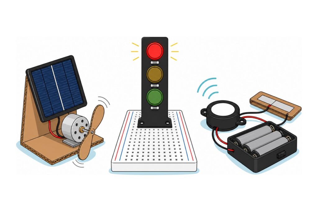
These three primary school science projects can be finished by a Year 4 to Year 6 pupil with no coding and no soldering: a mini solar fan, a mini traffic light, and a door alarm. Every one runs on 4.5 V or less, every one joins together by twist-and-tape or push-a-pin-into-a-hole, and each one answers the question science fair judges actually ask: which energy turns into which.
The parts that need adult hands come in only two kinds: cutting and drilling, and stripping and twisting wire. If your child is in Form 1 to Form 3 and this is RBT coursework, our list of RBT project ideas suits better.
Why do these three projects suit a science competition?
Science and innovation fair judges ask two things: what is happening inside, and what does this pupil genuinely understand. All three projects below are built on the same two ideas, so one pupil can explain every one of them with the same sentences.
First idea: a circuit must be complete, and a switch is only one gap in that circuit that we can open and close. Current flows only if there is a closed path from one end of the battery, through the components, and back to the other end. Break that path anywhere and everything stops at once, not gradually, because electrons do not queue up inside the wire — the whole chain moves together, or it does not move at all. That is why a switch is not a magic device: it sends no instruction to the lamp, it only closes or widens that gap. The ON/OFF switch on the battery box, a jumper moved between lamp rows, and two pieces of foil meeting when a door opens are the same thing in three different outfits.
Second idea: energy does not simply appear, it changes form. The solar fan turns light → electricity → motion. The traffic light and the alarm turn chemistry (inside the AA cells) → electricity → light or sound. When a judge asks “how does it work”, that chain is the answer.
Parts list — all three projects
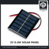 3V/5V Solar Panel Mini Solar Panel 100mA 0.3W 5V 0.23W 5.5V 1.1W - 3V 0.3W SOLAR PANEL
 DC Solar Motor DC 1.5V 3V 3.3V 5V Mini Round DC Motor For Arduino IOT Solar Project
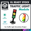 3 LED Traffic Light Module Red Yellow Green 5V 4 Pin Traffic Light Simulation
 SFM-20B Active Buzzer DC 3-24V Piezoelectric Long Continous Beep
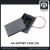 AA Battery Holder with Cover On/Off Switch 2/3/4 Slots Battery AA Holder Red/Black Wire - AA BATTERY CASE (3S)
 MB102 Breadboard 170 400 830 Holes Breadboard Donut Board Arduino Prototype Multi Color - BREADBOARD (400 HOLES)
 40pcs Dupont Wire 10cm 20cm 30cm for Breadboard DIY Experiment Jumper Wire Breadboard wire - DUPONT WIRE M-M 20CM
Optional extras
 Electronic Component Set Beginner Electrical Learning Kit For Arduino Beginner Learning - ELECTRICAL STARTER KIT
 40pcs Dupont Wire 10cm 20cm 30cm for Breadboard DIY Experiment Jumper Wire Breadboard wire - DUPONT WIRE M-F 20CM
 Crocodile Clip Cables 46cm Alligator Clip Cable Multi Color
The Electrical Starter Kit if you want one complete box for a whole class; male-to-female jumpers so modules can be connected without a breadboard; crocodile clip leads, the most classic solderless connector for school projects.
The battery box is listed twice for a practical reason: the traffic light and the door alarm each need their own supply, so two projects can stand live on the competition table at the same time with nothing unplugged. The solar fan uses no battery at all except on a cloudy day, and then it can borrow either of those two boxes.
Project 1: The mini solar fan — how does light become wind?
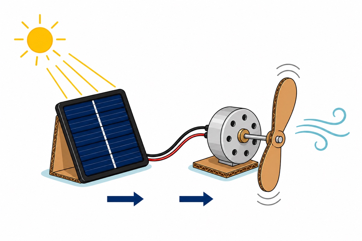
The 3 V 0.3 W solar panel and the 1.5–5 V solar DC motor connect straight to each other, with nothing in between. The reason is in the numbers: 0.3 W at 3 V means the panel can supply 0.1 A, or 100 mA, in full sun — while that motor draws roughly 12 mA at 3 V with no load. That is eight times more than the motor needs, and that is before the blade goes on.
Once the blade is fitted the current rises, because the motor has to work harder. The solar panel cannot be damaged by being pulled too hard, and the reason lies in how the cell makes current: every particle of light it absorbs frees one charge carrier, so the number of electrons per second the panel can deliver is set by how much light falls on it, not by how hard the motor pulls. Ask for more than that and the panel’s voltage drops by itself until the demand matches again — the fan simply spins slowly, and nothing burns. It is also why a palm covering part of the panel during a demo can stop the fan outright. The six blue cell strips on that panel are wired in series, so the same current must pass through all of them and the darkest strip sets the limit for the whole panel: covering one strip completely already drops the whole panel’s power almost to zero, not merely by one sixth. That on its own is a lovely experiment to show a judge.
Both parts arrive with red and black wires already attached at the factory, so the real work is only this: red to red, black to black, twist tight, wrap in electrical tape.
The fan blade: cut a two-blade propeller from thick cardboard or the wall of a plastic bottle with both halves the same length, find its centre by drawing two diagonals, and make a hole slightly tighter than 2 mm before pushing it onto the motor shaft (2 mm diameter, 7 mm long) — a loose hole lets the blade fly off at speed. Test the balance before switching on by hanging the blade on a pin: if the same half always falls to the bottom, trim a little off the tip of that half until the blade settles in a random position. An unbalanced blade vibrates, makes the motor noisy, and works that hole loose again. Cutting and drilling are adult jobs, and a spinning blade is kept away from faces and eyes. If you want a ready-made blade, our solar fan kit supplies a complete set.
One motor habit to understand before competition day: a motor that is still standing still draws the highest current. Until it turns it generates no back-EMF, the opposing voltage that normally throttles its own current, so the only thing limiting current at that moment is the very low resistance of the coil. In weak light the panel cannot deliver that starting current, its voltage sags, and the fan only buzzes without turning even though the circuit is correct. The cure is not an extra component: flick the blade once with a finger and the motor carries on by itself, because the current to keep spinning is far smaller than the current to start spinning. Tilt the panel to face the sun square on, too, not flat.
Bring a 3×AA battery box as cloudy-day insurance: three cells give 4.5 V, still inside the motor’s 1.5–5 V range, so simply swap the panel for the battery box and the fan spins indoors. Better still, compare the speed from both sources in front of the judges — that is an experiment, not just a demonstration. For bigger panels and how they charge a battery, see our solar panel guide.
Script for the judges: “This panel contains silicon cells. When sunlight hits them, the cells push electrons and produce an electric current. The current flows to the motor, the motor turns it into rotation, and the blade pushes air — so light becomes wind.”
Project 2: The mini traffic light — how does one jumper light three lamps?
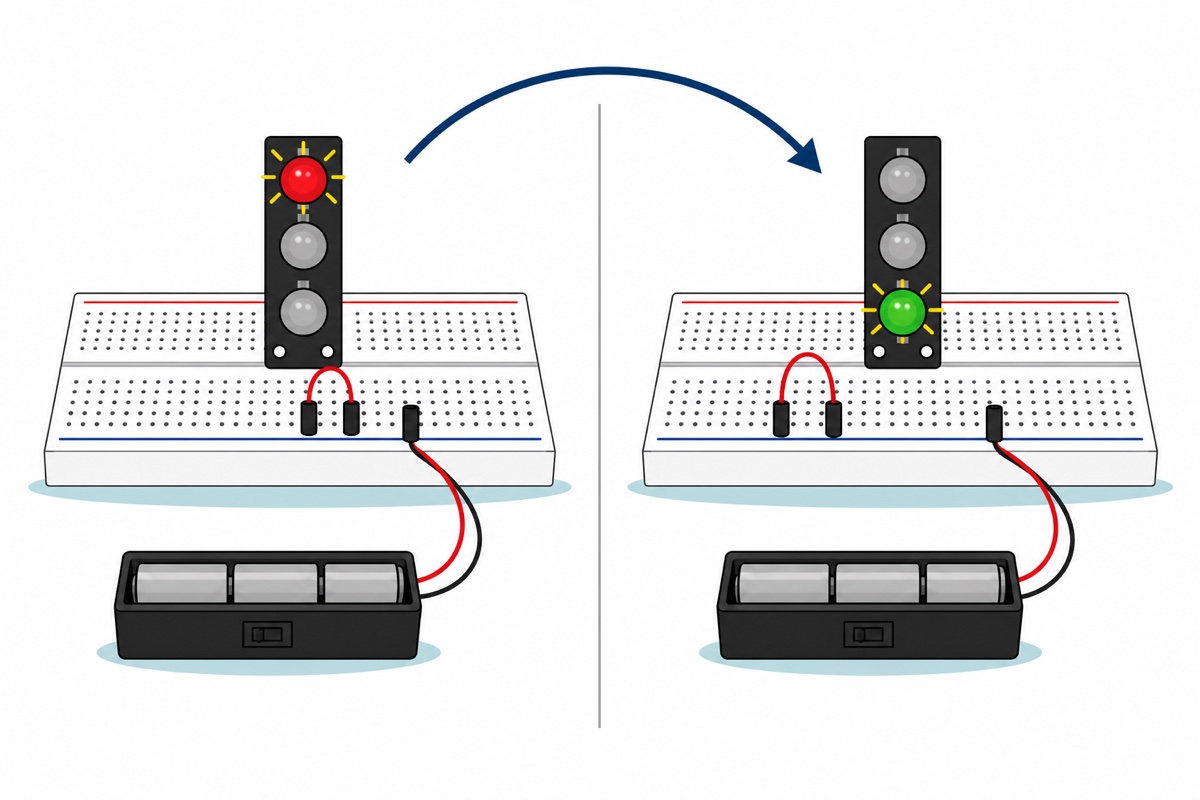
The 3-LED traffic light module is a thin black board with three large dome LEDs stacked vertically — red on top, yellow in the middle, green at the bottom — and four male pins along its bottom edge. Each LED already has its own small resistor beside it on the same board. That is why this module can be connected straight to a 5 V DC supply, and why this project needs no separate resistor at all.
Read the silkscreen labels on the board itself — G, Y, R and GND — do not count pin positions from memory. GND is the shared pin for all three LEDs; the other three each light one colour.
Push all four pins into a 400-point breadboard. Inside the breadboard, five holes in one row are joined by a hidden metal clip, so the hole beside the R pin is the same electrical point as that R pin itself. The battery wires need an anchor point first, because they end in stranded wire rather than a pin: twist each end onto the pin of a male-to-male jumper (how, in the connections section below), then push that red pin and that black pin into two separate empty rows. Run one jumper from the black row to the GND row, and one more jumper from the red row to the R row — that second jumper is the one the pupil moves between the R, Y and G rows. Each time the jumper moves, a different circuit becomes complete and a different lamp lights. That is a switch — made by the pupil’s hand, not by code.
At 4.5 V rather than 5 V all three lamps glow slightly dimmer, and the reason can be explained to a judge. Each LED holds its own fixed voltage — for ordinary red, yellow and green dome LEDs like the ones on this module, about 2 V — and the remainder drops across the small resistor beside it. When the supply falls by 0.5 V, that entire 0.5 V comes out of the resistor’s share alone, not the LED’s, so the current drops by roughly one sixth — about five sixths of the original is left. The colour that needs the highest voltage suffers first, so light all three together before competition day and see for yourself. It is still bright enough for a competition table.
This same physical module can be driven by an Arduino later: our Arduino traffic light guide is the next step.
Script for the judges: “Three AA cells turn chemical energy into electrical energy. When I put the jumper in the red row, I complete only the red circuit, so only the red LED lights. A real traffic light does the same thing — only its selector is a timer circuit, not my hand.”
Project 3: The door alarm — how do cardboard and foil become a switch?
The SFM-20B active buzzer is the simplest component in this list: give it 3–24 V DC on its red and black wires and it sounds straight away. “Active” means the oscillator is already built into that black case, so a flat DC voltage is enough to produce a tone — no pulsing signal, no code. A passive buzzer does not behave that way; the difference between active and passive buzzers explains why. One practical warning: this buzzer is loud, around 100 dB up close. Do not test it while holding it beside your ear, and if it is too loud for an enclosed hall, one small strip of tape over its sound hole is enough to quieten it without changing the circuit.
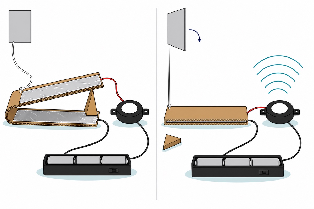
The door switch is home-made, and this is the part judges enjoy most. Fold a piece of cardboard into a clothes-peg shape. Stick aluminium foil onto both inner faces. Joining a wire to foil is the step that fails most often, because aluminium foil does not take ordinary solder and its surface always carries a thin insulating oxide layer. The method that works: lay the stripped wire end underneath the foil before the foil is stuck down, so the foil presses the wire flat against the cardboard, then lock it with tape around the edge. If you have crocodile clips, biting the edge of the foil works too — the clip’s teeth are what scrape through the oxide layer until metal meets metal. Slip a small cardboard wedge between the two faces so the foils cannot touch, then tie a string from that wedge to the door handle.
When the door opens, the string pulls the wedge out, the cardboard closes on itself, the two pieces of foil meet, the circuit becomes complete — and the buzzer sounds. Keep the foil surfaces flat and wide, because crumpled foil touches at only a few small points and the alarm then sometimes fails to sound.
Script for the judges: “This buzzer needs only a complete circuit to sound. While the door is shut, the cardboard wedge breaks that circuit. Opening the door pulls the wedge out, the two pieces of foil meet, the circuit is complete, and electrical energy becomes sound energy.”
How is each project connected?
In all three projects, the battery box comes out with stranded wire whose ends are bare. Those fine strands splay apart when pushed into a breadboard hole and can touch a neighbouring hole. The right way is to twist that end as tightly as possible onto the male pin of a jumper and wrap the joint in tape — an adult job. Crocodile clip leads are the classic shortcut for school projects; when to use crocodile clips explains their limits.
| Project | Connect from | Connect to | Note |
|---|---|---|---|
| Solar fan | Panel red / black | Motor red / black | Twist and tape; reversed = the motor just spins the other way |
| Solar fan (cloudy) | Battery red / black | Motor red / black | 4.5 V, inside the motor’s 1.5–5 V range |
| Traffic light | Battery black, via two jumpers | Breadboard row facing the GND pin |
Shared pin for all three LEDs |
| Traffic light | Battery red, via two jumpers | Row R, Y or G |
Move the jumper to change the lamp |
| Door alarm | Battery red | Foil A | The home-made switch sits here |
| Door alarm | Foil B | Buzzer red | — |
| Door alarm | Buzzer black | Battery black | Completes the circuit |
Which parts must an adult do?
All of these projects run on 4.5 V or less, a voltage that cannot give an electric shock through dry skin, and not one of them touches mains power. The real hazard is not the pupil but the battery: never let the bare ends of the battery box’s red and black wires touch each other. Three AA cells can supply enough current to heat the wire until it burns skin and ruins the cells themselves. Use the ON/OFF switch on the battery box whenever the project is resting, and take the cells out after the competition. One more small but real hazard: a cardboard fan blade spins at thousands of revolutions a minute, so run the fan on a table, keep eyes away from it, and tie back long hair.
| Step | Who |
|---|---|
| Cutting and drilling cardboard, plastic bottles and fan blades | Adult |
| Stripping, twisting and wrapping wire ends | Adult |
| Fitting the cells into the battery box | Pupil |
| Pushing modules and jumpers into the breadboard | Pupil |
| Sticking foil, tying the string, testing, and explaining to the judges | Pupil |
Common mistakes we see
Battery wires pushed straight into the breadboard. The fine strands splay, some of them land in a neighbouring hole, and the circuit behaves at random — which looks exactly like a faulty part. Twist that end onto a jumper pin first.
A palm covering the panel during the demo. Because those six cell strips are wired in series, one finger crossing even a single strip is enough to weaken the fan, and the judge sees a project that “did not work”. Stand the panel on a cardboard support and do not hold it at all.
Expecting the buzzer to sound through water or skin. Water sensor and touch sensor ideas are very popular, but water and skin have high resistance, so the current that gets through is far smaller than the buzzer needs. A circuit like that needs a transistor to amplify that tiny signal — which is why it is a secondary school science project, not a primary school one.
Reversed polarity, then blamed on a broken component. At 4.5 V, reversing damages nothing here: the motor simply spins the other way, and the LEDs and buzzer merely stay silent. Swap those two wires before changing anything else.
FAQ
What is the easiest primary school science project?
The solar fan. It is only two components, both already wired, the connection is red to red and black to black, and it works the moment you carry it out into the sunlight.
Can you build an electronics project without soldering?
Yes. All three of these projects use three solderless methods: twist-and-tape, breadboard, and crocodile clips. Solder is only needed when a joint has to last for a long time.
How long does one primary school science project take?
About one to two hours per project, including cutting cardboard and testing. All three can be finished over a single weekend.
What is the difference between a primary and a secondary school science project?
In primary school, judges assess whether the pupil understands what is happening inside the circuit. A secondary school science innovation project is expected to add a component that makes a decision or amplifies a signal: a transistor, a sensor or a microcontroller.
What do school science innovation judges look for?
An energy conversion chain the pupil can state clearly, one real problem the project tries to solve, and evidence the pupil built it themselves. A working model with a weak explanation always loses to a simple model explained with confidence.
Last updated August 2026. Stuck? Chat with us on WhatsApp.
