

Tutorials
Arduino PIR Sensor (HC-SR501): Code, Trimmers and False-Trigger Fixes
Aug
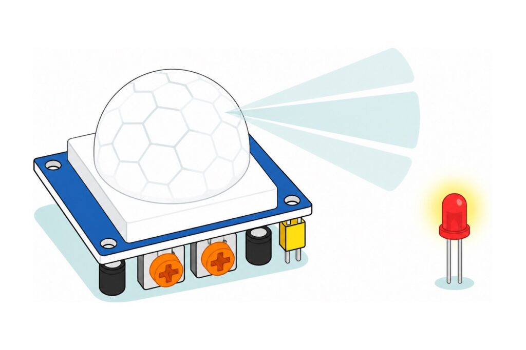
An HC-SR501 does not detect people — it detects a change in the infrared reaching its two sensing slabs. That one sentence explains both classic complaints: the light that never switches off, and the sensor that “forgets” you the moment you stand still. The recipe is short — Tx trimmer at minimum, jumper on L, hold time kept in code — and then the Arduino owns the timing instead of fighting the sensor.
What do you need to build an HC-SR501 motion light?
The HC-SR501 needs three wires and nothing else: power, ground, and one signal pin into the Arduino. Everything below the sensor is the output side — an LED to see the trigger, a buzzer to hear it, and a breadboard so nothing needs soldering.
Parts list — HC-SR501 motion light and alarm
 PIR Motion Sensor HC-SR501 MN-SR501 MINI Human Sensor Human Detector Motion Detector Arduino HCSR501 MNSR501 - HC-SR501 PIR MOTION SENSOR
 Arduino Compatible UNO R3 FT232 Development Board Arduino Compatible CH340 Alternative
 Buzzer Active Passive Buzzer 5V Electronic Sound Alarm Module Tone Piezo - Active Buzzer Module
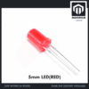 Round Head LED 3mm / 5mm / 8mm - Red/Yellow/Blue/Green/White - 5mm LED (RED)
 400 pcs 1/4W Resistor Pack Resistor Kit 20 Common Value with 20 each
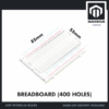 MB102 Breadboard 170 400 830 Holes Breadboard Donut Board Arduino Prototype Multi Color - BREADBOARD (400 HOLES)
 40pcs Dupont Wire 10cm 20cm 30cm for Breadboard DIY Experiment Jumper Wire Breadboard wire - DUPONT WIRE M-M 20CM
 40pcs Dupont Wire 10cm 20cm 30cm for Breadboard DIY Experiment Jumper Wire Breadboard wire - DUPONT WIRE M-F 20CM
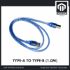 Data Cable Type-A Type-C MicroUSB Type-B 0.5m 1m 30cm 0.3m 100cm Data Transfer Upload Code - TYPE-A TO TYPE-B (1.0M)
Parts list
| Item | Price | Qty | |
|---|---|---|---|
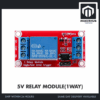 Relay Module 3.3V 5V 12V 1/2/4/8 Ways Optocoupler Trigger Relay Module 1 2 4 8 Channel Relay Module - 5V RELAY MODULE(1WAY)1WRELAY Relay Module 3.3V 5V 12V 1/2/4/8 Ways Optocoupler Trigger Relay Module 1 2 4 8 Channel Relay Module - 5V RELAY MODULE(1WAY)1WRELAY | RM3.15 |
Swap the single LED for a real 12 V LED strip or DC lamp — you supply the 12 V separately, it does not come from the Arduino. Low-voltage DC only; read our relay safety guide before wiring anything larger.
Two gender details decide whether this build is solder-free. The HC-SR501 and the MH-FMD buzzer module both present male pins, so they need the female ends of male-to-female jumpers; male-to-male jumpers handle breadboard-to-Uno runs, and the 5 mm red LED and resistor legs push straight into the breadboard. The Uno programs over full-size USB-B, so it needs the A-to-B cable. Any resistor from 220 Ω to 1 kΩ will do if you already own one; the 400-piece pack is the catalogue’s fixed-resistor option.
Why does a PIR sensor see movement but not people?
The HC-SR501’s sensing element is a pyroelectric detector containing two slabs of crystal wired in opposition. Warm objects radiate infrared around 8–14 µm; when that radiation falls equally on both slabs, their outputs cancel and the module reads zero. A room full of warm furniture, or a person standing perfectly still, produces exactly that balanced, unchanging picture — which is why a PIR is blind to a stationary body no matter how warm it is.
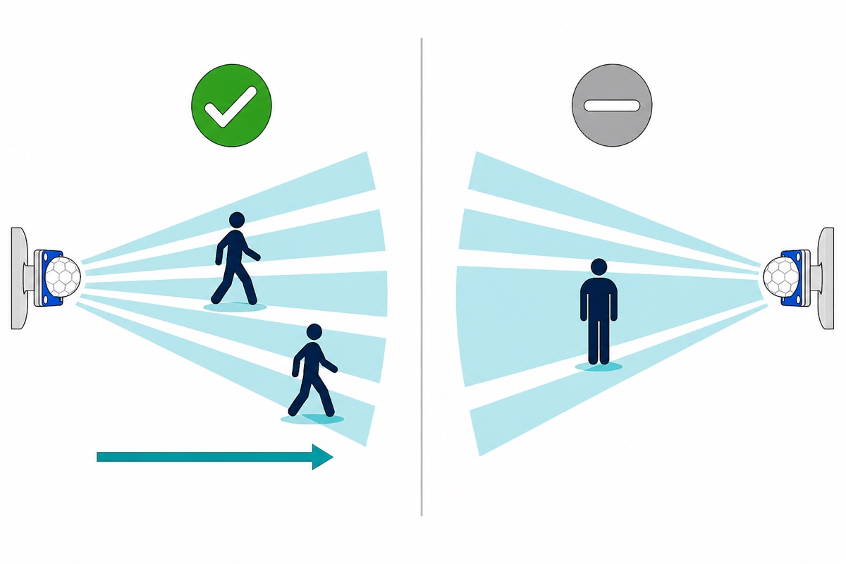
The white honeycomb dome is a Fresnel lens, and it is what turns that limitation into a motion detector. Each facet focuses a different narrow wedge of the room onto the element, so the field of view is not one smooth cone but dozens of alternating beams inside a cone of roughly 120° reaching 3–7 m. Walk across those beams and your heat lands on one slab, then the other, producing a positive pulse followed by a negative one — a change the amplifier can see. Walk straight towards the sensor and you cross far fewer beam boundaries, which is why head-on approaches trigger later and less reliably than crossing traffic.
The same physics explains the warm-up. The amplifier chain runs at enormous gain and passes only changes, so at power-on it has to settle to its own baseline first. Give the module about a minute after power-up, during which it will happily fire on nothing.
How do you wire the HC-SR501, LED and buzzer to an Uno?
The HC-SR501’s output is 3.3 V, not 5 V, because the module regulates its own supply down and the output stage swings to that internal rail. The Uno reads a HIGH from 0.6 × VCC upwards — 3.0 V on a 5 V board — so 3.3 V clears the threshold with 0.3 V to spare.
| From | To | Why |
|---|---|---|
| HC-SR501 VCC (an outer pin) | Uno 5V | Module accepts 5–20 V and makes its own logic rail |
| HC-SR501 OUT (always the centre pin) | Uno D2 | 3.3 V when triggered, 0 V when idle |
| HC-SR501 GND (the other outer pin) | Uno GND | Shared return. The outer two swap between board revisions, and the VCC/GND silkscreen usually sits on the board under the white dome rather than beside the header — read your own board before powering up, because swapping VCC and GND drives the module backwards and can destroy it |
| Buzzer VCC / GND | Uno 5V / GND | Module has its own driver transistor |
| Buzzer I/O | Uno D8 | Sounds when this pin is pulled LOW |
| LED long leg (anode) + one 220 Ω resistor leg | Same breadboard row | The breadboard is what joins them — five holes in one row are a single node, so no soldering |
| Resistor’s other leg (its own row) | Uno D9 | (5 − 2.0) V ÷ 220 Ω ≈ 14 mA, inside the 20 mA per-pin figure |
| LED short leg (cathode, its own row) | Uno GND | Male-to-male jumper closes the circuit |
The MH-FMD module’s silkscreen marks I/O as a low-level trigger, so its transistor turns the buzzer on when that pin goes low — which means a freshly configured output pin, sitting at 0 V, makes it shriek at boot. The sketch below writes HIGH before calling pinMode(OUTPUT), which works because digitalWrite() sets the same port-register bit either way: on an input that bit only arms the pull-up, and the moment the pin becomes an output the same bit is already the output level, so the pin is never driven to 0 V.
What do the two orange trimmers and the yellow jumper actually do?
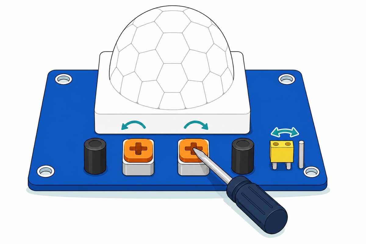
The HC-SR501 carries its own timing hardware, and that is the part that quietly fights your code. One orange trimmer sets sensitivity — how far away a body still registers, roughly 3 m to 7 m. The other sets Tx, how long OUT stays high after a trigger, from a few seconds at one stop to about five minutes at the other. The yellow jumper picks the retrigger mode. On H, movement during the Tx period restarts the timer, so OUT stays high while somebody keeps moving. On L it runs once and drops regardless. Either way a fixed blind window of about 2.5 s follows before anything can retrigger — invisible on H, felt after every pulse on L.
HC-SR501 boards come from several factories and published guides contradict each other about which trimmer sits where, so identify yours in a minute, with power on and the sketch running:
- Turn both trimmers gently anticlockwise to their stops with a small flat screwdriver. Do not force them.
- Wave once, then time how long the LED stays lit. Turn one trimmer a quarter turn clockwise and wave again. If the on-time changed, that is Tx; if only the distance at which you get noticed changed, that is sensitivity.
- Mark the Tx one with a dot of marker pen.
The settings that make software timing work are Tx at its minimum and the jumper on L. At minimum, Tx holds the output high for roughly three seconds, and the blind window that follows is of the same order, so somebody moving around continuously still re-triggers the output at least once every six seconds or so. Any hold time in code that is comfortably longer than that — ten seconds and up — can never be cut short by the sensor’s own dead time.
| Symptom | Cause | Fix |
|---|---|---|
| Light stays on for minutes after everyone leaves | Tx wound clockwise; on H, every passer-by restarts it | Tx to minimum, jumper to L, hold the time in code |
| Output drops while you are still in the room | You stopped moving — balanced slabs, no change | Expected behaviour; extend the hold time in code |
| Second wave right after the first is ignored | The blind window after each pulse | Wait a few seconds, or use H so the timer refreshes instead |
| Wild triggering for the first minute after power-up | Amplifier still settling | Ignore the pin until the warm-up has elapsed |
Changing delay() values changes nothing |
Tx is longer than your code’s timing | Turn Tx down before blaming the sketch |
Seeing a screwdriver actually turn those trimmers helps:
The sketch: let the Arduino own the hold time
No library is needed: a PIR is a plain digital input, so digitalRead() and millis() are the whole toolkit. Upload with the board set to Arduino Uno, then open the Serial Monitor at 9600 baud. Nothing here calls delay(), so the chirp and the light timer run independently. It compiles to 2,318 bytes, about 7% of the Uno’s flash.
// HC-SR501 motion light + alarm beep, with the hold time owned by the sketch.
// Sensor settings this expects: Tx trimmer at its minimum, jumper on L.

const uint8_t PIR_PIN    = 2;   // HC-SR501 OUT (the centre pin of its 3-pin header)
const uint8_t LED_PIN    = 9;   // LED anode through a 220 ohm resistor to GND
const uint8_t BUZZER_PIN = 8;   // MH-FMD active buzzer I/O - it sounds on LOW

const unsigned long WARMUP_MS = 60000UL;  // ignore the sensor while it settles
const unsigned long HOLD_MS   = 15000UL;  // how long the light stays on
const unsigned long BEEP_MS   = 300UL;    // one short chirp per new visitor

bool lightOn = false;
unsigned long lastMotionMs = 0;

bool beeping = false;
unsigned long beepStartedMs = 0;

// The buzzer module is a LOW-level trigger: pulling I/O LOW makes it sound.
void buzzer(bool on) {
  digitalWrite(BUZZER_PIN, on ? LOW : HIGH);
}

void setup() {
  Serial.begin(9600);

  pinMode(PIR_PIN, INPUT);

  pinMode(LED_PIN, OUTPUT);
  digitalWrite(LED_PIN, LOW);

  // Set the level BEFORE the pin becomes an output. A fresh output pin
  // starts LOW, and LOW is exactly what makes this buzzer scream, so
  // writing HIGH first (it arms the pull-up) keeps boot silent.
  digitalWrite(BUZZER_PIN, HIGH);
  pinMode(BUZZER_PIN, OUTPUT);

  Serial.println(F("Warming up - ignoring the sensor for about a minute."));
}

void loop() {
  unsigned long now = millis();

  // Subtracting unsigned longs stays correct when millis() rolls over, which is
  // why the hold and beep timers below are written as (now - then >= limit).
  // The warm-up is a one-shot test on millis() itself, so it simply runs once
  // more for a minute if the board is still up at the 49-day rollover.
  bool warmedUp = (now >= WARMUP_MS);
  bool motion   = (digitalRead(PIR_PIN) == HIGH);

  if (motion && warmedUp) {
    lastMotionMs = now;               // refresh the hold on every pulse

    if (!lightOn) {                   // a NEW visitor, not the same one still moving
      lightOn = true;
      digitalWrite(LED_PIN, HIGH);
      beeping = true;
      beepStartedMs = now;
      buzzer(true);
      Serial.println(F("Motion detected"));
    }
  }

  if (lightOn && (now - lastMotionMs >= HOLD_MS)) {
    lightOn = false;
    digitalWrite(LED_PIN, LOW);
    Serial.println(F("Quiet again"));
  }

  if (beeping && (now - beepStartedMs >= BEEP_MS)) {
    beeping = false;
    buzzer(false);
  }
}
Raise HOLD_MS for a corridor light, or lengthen BEEP_MS into a proper alarm the way our flame-sensor alarm guide does.
Why does it trigger when nobody is there?
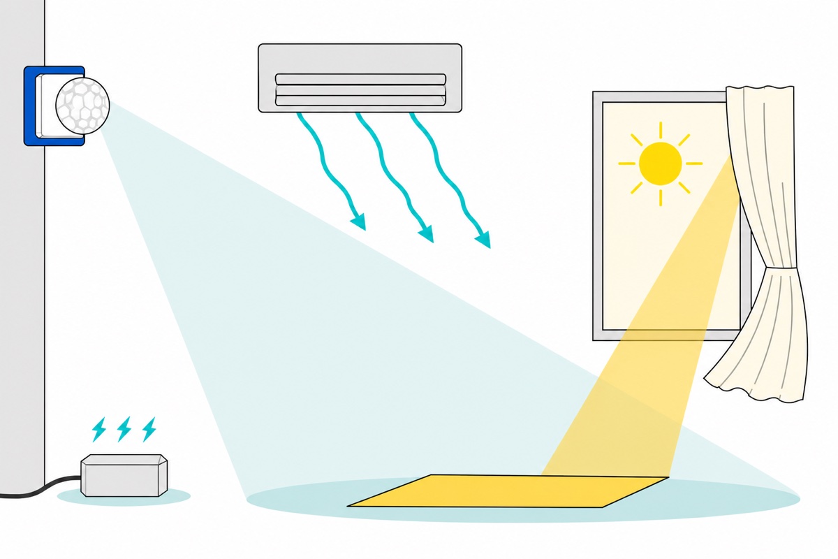
False triggers on the HC-SR501 are almost always real infrared changes that you did not think of as motion. Air conditioning and fans are the usual culprit — not because moving air is visible to the sensor, but because it sweeps warm and cool surfaces across the field of view and cools the sensing element unevenly, so the two slabs stop agreeing. Aim the dome away from vents and never mount it in a direct draught.
Sunlight is the second cause. Daylight carries plenty of infrared, so a sun patch creeping across a floor, or cloud shadow crossing a window, is a genuine change in the picture. Keep windows and glass doors out of the cone, or gate the output by time or by a light sensor.
The third cause is electrical. The module amplifies microvolt-level signals, so a sagging or noisy 5 V rail lands on the comparator input as if it were a signal. A relay coil or a motor sharing the Uno’s 5 V pin will dip that rail every time it switches — a false trigger arriving at the exact moment your output activates is this, not a haunted sensor. Give the loads their own supply with grounds tied together.
Reach for the sensitivity trimmer only after those three. Turning it down shrinks detection distance, which hides the symptom rather than curing it.
From an LED to a real lamp
Point LED_PIN at a relay instead and the same sketch switches a 12 V LED strip or DC lamp. The 5 V relay module runs its coil from the Uno’s 5 V pin — one coil draws on the order of 70 mA, which a USB-powered Uno supplies, though a bank of them will not — and its control side is a three-way screw terminal, so a jumper’s bare male pin clamps straight in.
The switched side is a dry contact, not an output — the relay only closes a switch between COM and NO, so the lamp and its own 12 V supply form a loop that never touches the Arduino’s ground.
Check the module’s small high/low trigger jumper before you write any code: it decides whether the coil energises on a HIGH or a LOW, and boards ship set either way. Confirm with a single digitalWrite and your ear. If you already run a 12 V system, the 12 V coil version is the right part instead — it simply has no 12 V rail to run from in this build.
Keep the switched side low-voltage DC. Those contacts are rated for mains, and mains switching brings clearance, insulation and enclosure requirements that belong in our relay module safety guide — read it before going anywhere near 240 V.
Common mistakes we see from real customers
Testing immediately, while leaning over the board. Your own arm fills the cone during the warm-up minute. Power it, walk away, come back.
Blaming the sketch for the sensor’s timer. If the light stays on far longer than HOLD_MS, the Tx trimmer is set long and the Arduino is simply waiting for OUT to go low. Software cannot shorten hardware.
Wiring the buzzer as an active-high device. It screams from boot and never stops, which reads as a faulty module. HIGH is silence.
Expecting a PIR to count people or measure distance. It reports “something changed in the cone”, nothing more; ranging is a job for our HC-SR04 guide.
FAQ
Which orange trimmer is sensitivity and which is time delay?
Turn one a quarter turn and wave. If the on-time changes it is Tx, the time delay; if only the detection distance changes, it is sensitivity.
Why does my motion light stay on for minutes?
The Tx trimmer is wound up and the jumper is on H, so each new movement restarts a long hardware timer. Turn Tx to minimum, move the jumper to L, and set the duration in code.
Can I connect an HC-SR501 to an ESP32 or Raspberry Pi Pico?
Yes. Its output swings to 3.3 V rather than to VCC, so no level shifter is needed. Feed VCC from the board’s 5 V pin — the module’s regulator needs more than 3.3 V in.
Should I use H or L on the yellow jumper?
Use L when your code keeps the timing, so the sensor cannot latch high. Use H when the sensor drives a relay or lamp directly with no microcontroller.
Why does it detect me at the door but not at my desk?
Doorway traffic crosses many Fresnel beams; someone at a desk sits inside one and barely moves. Mount it so people cross its view rather than approach it.
Last updated August 2026. Stuck? Chat with us on WhatsApp.
