

Tutorials
INA3221 Arduino Guide: Measure Voltage and Current on Three Rails at Once
Aug
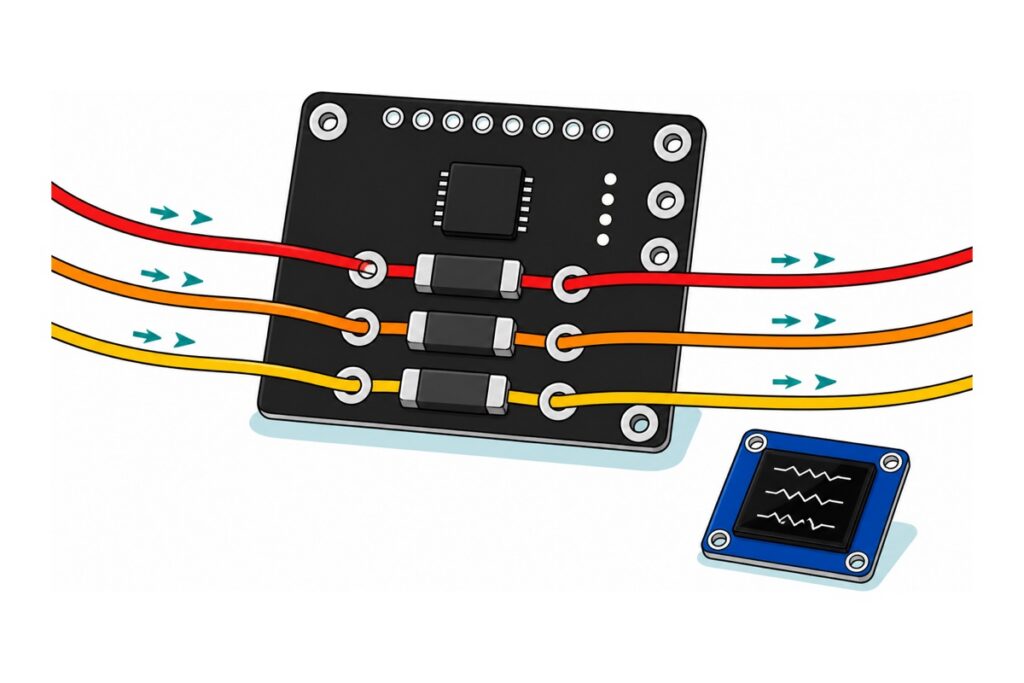
One INA3221 module watches three power rails at the same time. Route each rail through one of its three 0.1 Ω shunt resistors, join SDA and SCL to an ESP32, and live voltage, current and power for all three lanes arrive over a single I2C bus. This guide wires it up and turns the numbers into a live OLED readout.
How does the INA3221 measure current?
The INA3221 measures current by putting a known resistance in the path and reading the voltage that appears across it. Each of its three channels is a 0.1 Ω resistor — the blocks marked R100 — and Ohm’s law does the rest: 100 mA through 0.1 Ω drops exactly 10 mV. The chip’s differential ADC reads that drop and hands it over I2C — dividing by the resistance, which the sketch’s library does for you, gives the current. It also measures each rail’s voltage on the load side of the shunt, so one channel yields volts, milliamps and milliwatts.
The shunt is small on purpose. The TI datasheet gives the shunt input a ±163.8 mV full-scale range, so a heavy load costs the rail very little: at 500 mA the drop across 0.1 Ω is 50 mV — one percent of a 5 V rail — which is why the meter can live permanently inside a project without starving it. The chip senses high-side: in the positive wire, between supply and load, so the ground stays whole and shared — a low-side shunt in the ground return would lift the load’s “zero volts” by the shunt drop, and every ground-referenced signal, I2C included, would wobble with the load.
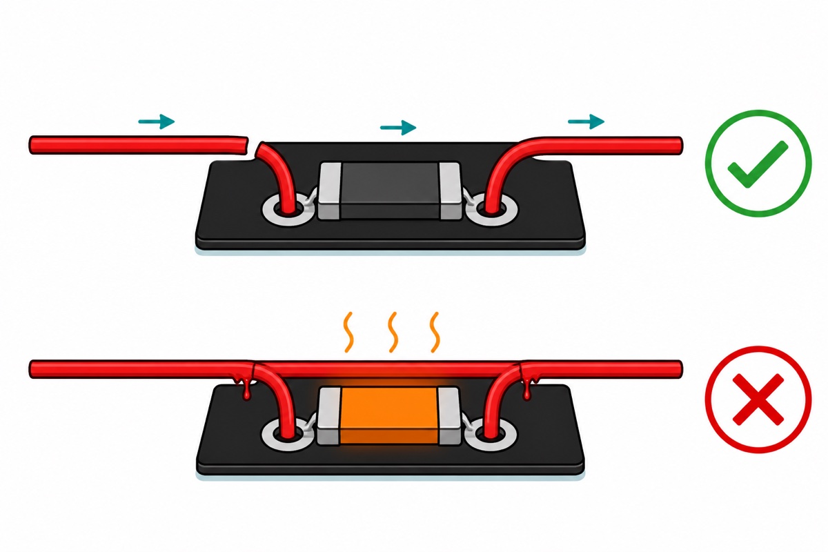
The same number explains the one wiring rule that can end in smoke. A channel must sit in series — the rail broken open, current entering one channel hole and leaving the other. Connect a channel pair in parallel across a rail instead and you have placed 0.1 Ω directly from supply to return: Ohm’s law asks a 5 V rail for 50 A, and the supply, the wire or the shunt gives up first.
The three channels are fully independent — each pair of large bottom-edge holes connects only to its own shunt, and the pairs are labelled VIN1+/VIN1− to VIN3+/VIN3− on the back of the board (the front shows just CH1–CH3). What they must share is ground: the chip measures each rail’s voltage relative to its own GND pin, so the board’s ground joins the ground of whatever it measures.
Parts list — the three-rail monitor, the board that reads it, and the wiring between
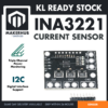 INA3221 Triple Channel Current Voltage Power Monitor Sensor Module I2C Interface for Arduino Raspberry Pi
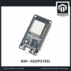 NodeMCU ESP32 Wi-Fi + Bluetooth Development Board CH340/CP2012 - For IOT Project - ESP-32(CP2102)
 0.96‘ OLED Display Module Blue White Screen I2C IIC Serial 128X64 LCD Display Board - 0.96' OLED WHITE
 40pcs Dupont Wire 10cm 20cm 30cm for Breadboard DIY Experiment Jumper Wire Breadboard wire - DUPONT WIRE F-F 20CM
 Breadboard Jumper Wire Set Male to Male Bread Board Wire Solderless Connection
Parts list
| Item | Price | Qty | |
|---|---|---|---|
 Soldering Service for Circuit Boards & Electronics - 10 Pins Soldering ServiceSOLSE10 Soldering Service for Circuit Boards & Electronics - 10 Pins Soldering ServiceSOLSE10 | RM1.40 |
The INA3221 arrives fully unsoldered: an 8-pin header plus the load wires for the channels you use. Add the 10-pin soldering service and we fit them for you — for a full three-channel hookup, message us on WhatsApp about the pin count first.
What needs soldering before anything works?
The INA3221 module ships as a bare board with a loose 8-pin male header strip — all seventeen plated holes are empty, so soldering comes first. The header goes into the small top-edge row (the square pad marks pin 1), and our header-soldering guide covers the technique. The channel pairs and the VPU/GND/GND block are larger, wire-scale holes: solder lengths of solid-core breadboard wire into the channels you plan to use — solid core holds its shape and takes solder cleanly — or fit KF301 screw terminals if you would rather clamp your rails.
How do you wire the INA3221 and OLED to the ESP32?
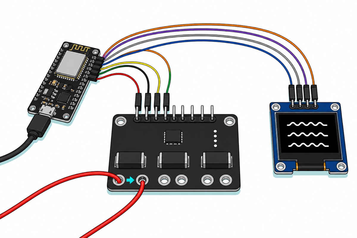
The INA3221’s 8-pin header reads, from the square pin 1: VS, GND, SCL, SDA, then PV, CRI, WAR and TC. Only the first four matter today — the rest are open-drain alert outputs: CRI and WAR fire on per-channel current limits you program, PV signals that every rail is up, and TC checks power-supply sequencing at power-up; leave them unconnected for now. The chip runs from 2.7–5.5 V, so the ESP32’s 3.3 V rail powers it directly:
| Module pin | ESP32 pin | Why |
|---|---|---|
| INA3221 VS | 3V3 | Chip supply — 2.7–5.5 V range, so 3.3 V logic levels match by design |
| INA3221 GND | GND | Reference for the bus voltage readings and the I2C bus |
| INA3221 SCL | D22 | The ESP32 Arduino core’s default I2C clock |
| INA3221 SDA | D21 | The ESP32 Arduino core’s default I2C data |
| OLED GND | GND | This module’s header is GND-first: GND VCC SCL SDA |
| OLED VCC | 3V3 | The SSD1306 runs happily from 3.3 V |
| OLED SCL | D22 | Same wire as the INA3221’s SCL — that is the point of a bus |
| OLED SDA | D21 | Same wire as the INA3221’s SDA |
Every hop is module-pin to module-pin, so female-to-female jumpers cover all of it with no breadboard: the ESP32 board and the 0.96-inch OLED arrive with male headers pre-soldered, and the INA3221 presents male pins once its strip is in. Note the OLED’s GND-first header order in the table — the reverse of many hobby modules. The INA3221 itself wires to a classic 5 V Arduino just as happily: VS to 5V, SDA to A4, SCL to A5.
Then come the rails themselves. Feed each lane you want to watch through a channel: supply side into VIN+, load side out of VIN−, up to 26 V per channel — low-voltage DC only, and nothing near mains. A natural first trio for an ESP32 project: channel 1 takes the board’s own supply — program over USB first, then unplug the cable and power the ESP32 through its VIN pin instead, the 5 V supply’s positive wire entering VIN1+, leaving VIN1− for VIN, and the supply’s ground joining the ESP32’s GND — so every milliamp the board draws crosses the shunt. Channel 2 takes the wire from the 3V3 pin to your sensors, and channel 3 a battery lane like the one in our TP4056 charging guide. Join the INA3221’s GND to the measured project’s ground; a channel that reads negative simply has its two wires swapped.
How do two I2C devices share the same two wires?
The OLED and the INA3221 coexist on D21/D22 because I2C is an addressed bus: every transaction starts with the master calling a 7-bit address, and only the device that owns it answers while the rest stay silent. This display answers at 0x3C (the module’s silkscreen says 0x78 — the same address with the read/write bit tacked on); the INA3221 answers at 0x40 as shipped — the address its A0 pin selects when tied to GND. The solder-pad pairs on the board’s left edge re-tie A0, allowing four boards on one bus — twelve monitored rails:
| A0 pad bridged to | I2C address |
|---|---|
| GND (as shipped) | 0x40 |
| VS | 0x41 |
| SDA | 0x42 |
| SCL | 0x43 |
Before any multi-device I2C build, run an I2C scanner sketch and confirm both 0x3C and 0x40 appear. Ten seconds of scanning turns “why is my screen blank” into “the bus is fine, look elsewhere”.
What does the monitor sketch look like?
Install INA3221_RT by Rob Tillaart and Adafruit SSD1306 from Library Manager (let the IDE pull in dependencies when it asks). The sketch prints volts, milliamps and milliwatts for all three channels several times a second, and between refreshes keeps sampling channel 1 fast, remembering the highest current it ever saw — the peak-hold line whose point the next section makes concrete.
// ESP32 + INA3221: live volts, milliamps and milliwatts for three rails
// on a 0.96in OLED. Both devices share one I2C bus: SDA = D21, SCL = D22.
#include <Wire.h>
#include <Adafruit_GFX.h>
#include <Adafruit_SSD1306.h>
#include <INA3221.h>            // library "INA3221_RT" by Rob Tillaart

Adafruit_SSD1306 oled(128, 64, &Wire, -1);
INA3221 ina(0x40);              // as shipped; A0 pads move it to 0x41-0x43

float peak = 0;                 // highest CH1 current seen since boot, mA

void setup() {
  Serial.begin(115200);
  Wire.begin();                 // ESP32 defaults: SDA 21, SCL 22

  if (!ina.begin()) {
    Serial.println("INA3221 not found at 0x40 - check wiring and address");
    while (true) delay(100);
  }
  ina.setShuntR(0, 0.100);      // the three R100 resistors on the board
  ina.setShuntR(1, 0.100);
  ina.setShuntR(2, 0.100);

  oled.begin(SSD1306_SWITCHCAPVCC, 0x3C);   // this module answers at 0x3C
  oled.setTextColor(SSD1306_WHITE);
}

void loop() {
  // Between screen refreshes, keep sampling CH1 fast and remember the
  // highest reading - this is what catches a WiFi transmit burst.
  for (int i = 0; i < 40; i++) {
    float mA = ina.getCurrent_mA(0);
    if (mA > peak) peak = mA;
    delay(5);
  }

  oled.clearDisplay();
  oled.setTextSize(1);
  for (uint8_t ch = 0; ch < 3; ch++) {
    oled.setCursor(0, ch * 12);                    // one line per rail
    oled.print("CH");
    oled.print(ch + 1);
    oled.print(" ");
    oled.print(ina.getBusVoltage(ch), 2);          // volts at VIN-
    oled.print("V ");
    oled.print(ina.getCurrent_mA(ch), 0);          // shunt drop / 0.1 ohm
    oled.print("mA ");
    oled.print(ina.getPower_mW(ch), 0);            // the two multiplied
    oled.print("mW");
  }
  oled.setCursor(0, 44);
  oled.print("CH1 peak: ");
  oled.print(peak, 0);
  oled.print(" mA");
  oled.display();
}
It compiles to 307,644 bytes — under a quarter of the ESP32’s sketch space. The library never invents numbers: it reads the raw shunt-voltage register, divides by the 0.1 Ω you told it about in setShuntR(), and multiplies by the bus voltage for power, which is why a board with different shunts only needs that one line changed.
What can these numbers tell you — and what can’t they?
The INA3221’s resolution comes straight from its ADC step. The shunt register counts in 40 µV steps, and 40 µV across 0.1 Ω is 0.4 mA — the smallest current change a reading can show. Stack up the full 4095 steps and you get the ±163.8 mV full scale, which divided by the same 0.1 Ω sets the ceiling: about ±1.6 A per channel. Past full scale the reading clips rather than climbs — treat a reading pinned near 1638 mA as “off the scale”, not a measurement.
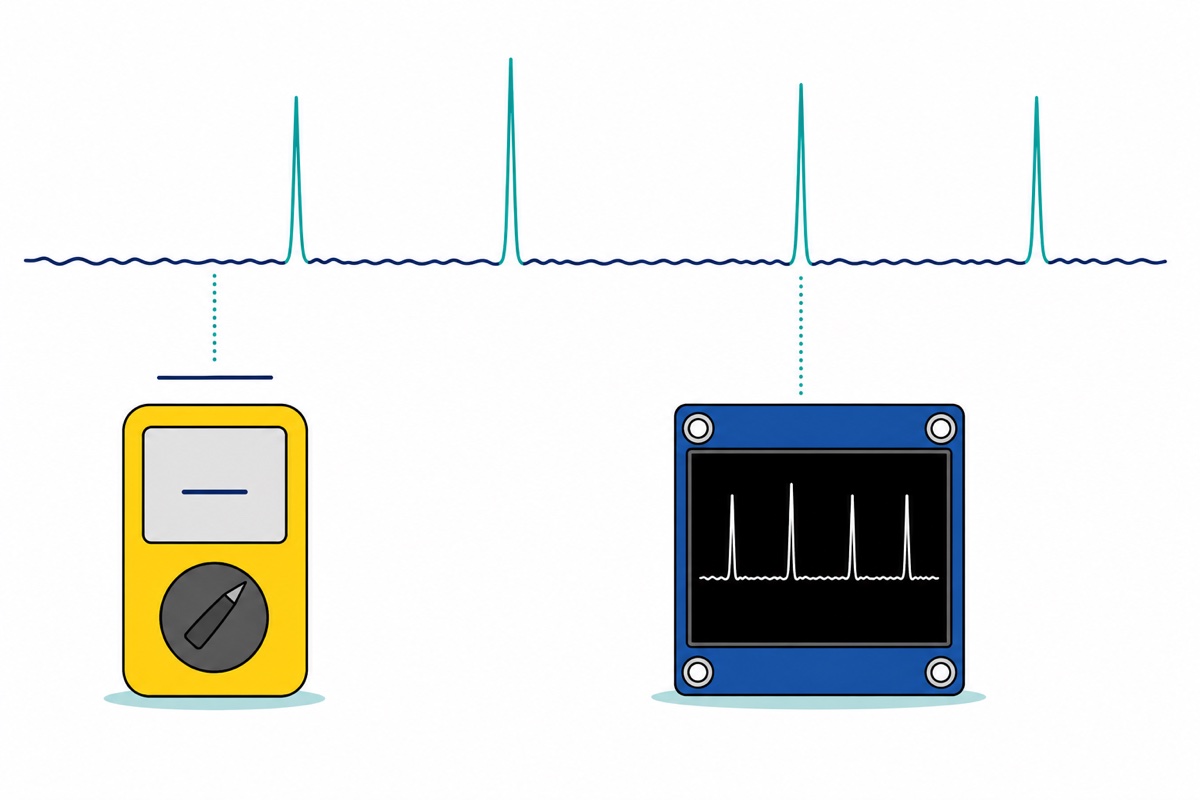
The reason to build a live monitor at all, when a multimeter already measures current, is time. A hand-held meter refreshes a few times a second and shows a smoothed value — exactly right for steady loads, exactly wrong for an ESP32, whose WiFi transmissions are millisecond bursts that the averaging folds into the background. The INA3221 converts continuously — at its default 1.1 ms per conversion it sweeps shunt and bus on all three channels roughly every 7 ms — and the sketch’s peak-hold keeps whatever the sweeps catch. The monitor sketch never turns the radio on itself, so give it something to catch — merge your project’s WiFi code into it, or just add a bare WiFi.begin() connection, whose transmit bursts are exactly this kind of spike. Watch the peak line sit far above the idle reading and our powering-ESP32 guide’s warning about weak supplies browning out on WiFi bursts stops being advice and becomes a number on your desk.
Common mistakes we see from real customers
The channel is wired across the rail instead of into it. That is the parallel short from earlier — 0.1 Ω straight across the supply. The rail must be broken, all its current entering VIN+ and leaving VIN−.
Voltage reads fine, current reads zero forever. Tapping VIN+ onto a rail without breaking it open measures its voltage happily, but the load’s current still takes its old path — none flows through the shunt, so there is nothing to read.
No shared ground with the measured project. The chip measures each bus voltage relative to its own GND pin. Power the monitor from one supply and the project from another without joining grounds and the voltage readings float into nonsense.
The OLED is wired VCC-first by habit. This display’s header is GND VCC SCL SDA, ground first, so habit-wiring from other modules reverses its supply. Read the silkscreen every time before power.
A 2 A load “measures” 1.6 A. That is the ±163.8 mV shunt range clipping, not the real current — this board’s sweet spot is the under-1.6 A world most ESP32 projects live in.
FAQ
Can the INA3221 measure more than 1.6 A?
Not with the 0.1 Ω shunts fitted to this board: the chip’s ±163.8 mV shunt input divided by 0.1 Ω caps each channel at about ±1.638 A, and readings clip there. The chip itself only sees millivolts, so boards built with smaller shunts trade resolution for range — the 0.4 mA step grows in proportion.
What is the difference between the INA3221 and the INA219?
The INA219 is the same idea — a high-side I2C shunt monitor — with one channel per chip. The INA3221 gives you three channels behind one address, plus programmable warning and critical alerts per channel — the better fit for watching a whole project’s power tree.
Does the INA3221 work with 3.3 V boards like the ESP32?
Yes. The chip’s supply range is 2.7–5.5 V, so it runs directly from the ESP32’s 3V3 pin and its I2C lines sit at safe 3.3 V levels. The 26 V figure is the ceiling for the rails being measured, not for the chip’s own supply.
Why is my current reading negative?
Current is counted positive flowing from VIN+ to VIN−, so a negative sign means that channel’s two wires are swapped — nothing is damaged. Swap them, or keep the sign to watch current flow both ways, as on a battery lane that charges and discharges.
Do I need the alert pins (PV, CRI, WAR, TC) for this build?
No — the sketch polls readings over I2C and never touches them. They are for hardware reactions without software: each channel can pull CRI or WAR low the moment its current crosses a programmed limit. The pins are open-drain; the VPU hole biases only the power-valid (PV) output, not the other alerts.
Power problems stop being guesses once every rail’s true draw is a number you can watch. Wire the shunt in series, share the ground, and the next time something browns out you will know which lane did it — and by how many milliamps.
Last updated August 2026. Stuck? Chat with us on WhatsApp.
