

Tutorials
MPU6050 (GY-521) Arduino Tutorial: Stable Tilt on an OLED
Jun
Wire the GY-521’s SDA and SCL to the Arduino Uno’s A4 and A5, wake the MPU-6050 from sleep, then divide the raw 16-bit readings by the datasheet scale factors — 16384 per g and 131 per °/s at the default ranges — and fuse accelerometer and gyro with a complementary filter for a stable tilt angle on the OLED.
What is on the GY-521 board and what do its eight pins do?
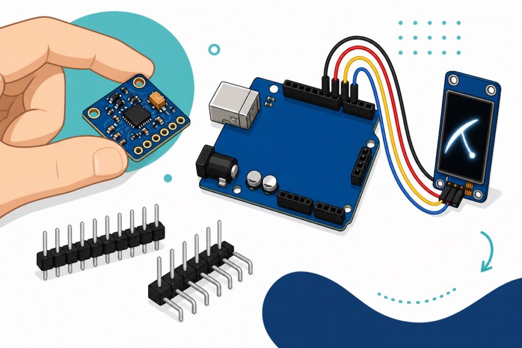
The GY-521 is a small blue PCB carrying InvenSense’s MPU-6050: a 3-axis gyroscope and 3-axis accelerometer in one black chip. The gyro covers ±250 to ±2000°/s, the accelerometer ±2 to ±16 g, and the board’s regulator accepts 3–5V — the MPU-6050 datasheet puts the bare chip at 2.375–3.46V, which is why the Uno’s 5V is safe here. Silkscreen arrows mark the X and Y axes.
Two of the eight gold pads confuse almost everyone. AD0 selects the I2C address: the board holds it low, so left unconnected the module answers at 0x68; tie it to 3.3V and it moves to 0x69 for a second module on one bus. XDA and XCL are the MPU-6050’s own auxiliary I2C master for chaining an extra sensor such as a magnetometer behind the chip — never wire your Uno into them.
The header pins arrive as two loose strips, one straight and one right-angle — solder on whichever suits your build with our header soldering guide. Do not push-fit them: a friction joint drops out the moment you tilt the board, which is the whole point of this project.
Parts list
 Arduino Uno Compatible SMD UNO R3 with Type B Cable - ATMEGA328P with CH340G-Microcontroller Project
 GY-521 Gyroscope Accelerometer Module MPU6050 MPU-6050 Motion Measurement Drone Robotic Application
 0.96‘ OLED Display Module Blue White Screen I2C IIC Serial 128X64 LCD Display Board - 0.96' OLED WHITE
Parts list
 MB102 Breadboard 170 400 830 Holes Breadboard Donut Board Arduino Prototype Multi Color - MINI BREADBOARD 170 HOLES (WHITE)
 40pcs Dupont Wire 10cm 20cm 30cm for Breadboard DIY Experiment Jumper Wire Breadboard wire - DUPONT WIRE M-M 30CM
Seat both modules on a breadboard and run male-to-male Dupont wires to the Uno — much steadier than loose wires on a board you keep tilting.
How do you wire the GY-521 and the OLED to the Uno?
The Arduino Uno exposes I2C on two analog pins: A4 is SDA and A5 is SCL. Both modules share those two wires plus power — eight jumper wires in total.
| Module pin | Uno pin | Notes |
|---|---|---|
| GY-521 VCC | 5V | Onboard regulator drops it for the chip |
| GY-521 GND | GND | — |
| GY-521 SCL | A5 | Shared I2C clock |
| GY-521 SDA | A4 | Shared I2C data |
| GY-521 AD0 | Not connected | Address stays at the default 0x68 |
| GY-521 XDA, XCL | Not connected | Auxiliary I2C master — not for the Uno |
| GY-521 INT | Not connected | Interrupt output, unused here |
| OLED GND | GND | First pin on this display — check the silkscreen |
| OLED VCC | 5V | Second pin, not first |
| OLED SCL | A5 | Same clock wire as the GY-521 |
| OLED SDA | A4 | Same data wire as the GY-521 |
Watch the OLED’s header order: it reads GND, VCC, SCL, SDA left to right, and swapping the first two pins is the classic way these displays die. Sharing one bus is no problem because I2C addresses every chip: the MPU-6050 answers at 0x68, this OLED at 0x3C, and the Uno calls each by name — the same pattern as our DHT11 OLED monitor.
To see the module wired and raw values moving on a real bench, this walkthrough shows the physical side well:
Why does the MPU6050 return huge numbers like 16384?
The MPU-6050 does not send degrees or g — it sends signed 16-bit integers from −32768 to +32767, and reading them as real units is the number one beginner mistake. Sitting flat on a desk, the Z accelerometer reads about 16384: not broken, just 1 g in raw counts. Divide by the sensitivity scale factor for your selected range, from the datasheet: 16384 ÷ 16384 = 1.00 g, and a gyro reading of 262 becomes 262 ÷ 131 = 2°/s. Neither divisor is arbitrary: +2 g owns the positive half of the 16-bit scale — 32768 counts — so one g is 32768 ÷ 2 = 16384, and 32768 ÷ 250 is where the gyro’s 131 comes from.
| Range setting | Divide raw value by | Result unit |
|---|---|---|
| Accel ±2 g (default) | 16384 | g |
| Accel ±4 g | 8192 | g |
| Accel ±8 g | 4096 | g |
| Accel ±16 g | 2048 | g |
| Gyro ±250°/s (default) | 131 | °/s |
| Gyro ±500°/s | 65.5 | °/s |
| Gyro ±1000°/s | 32.8 | °/s |
| Gyro ±2000°/s | 16.4 | °/s |
The trade is range versus resolution: the same 16 bits stretched over ±16 g make each count worth eight times more acceleration. This tutorial keeps the power-on defaults — ideal for tilt — and if you later widen the range, the divisor changes with it.
Why do you need both the accelerometer and the gyroscope?
The MPU-6050’s accelerometer gives you tilt almost free: tilt the board and gravity’s steady 1 g splits between the Y and Z axes, so atan2(ay, az) recovers the roll angle from that split — rock-stable over minutes. The catch: it measures every acceleration, not just gravity. Shake the board and the motion adds its own pull, the combined vector no longer points straight down, and the computed angle jumps wildly — exactly when things get interesting.
The gyroscope has the opposite personality: multiplying its rotation speed by the time step and summing — integrating — gives a smooth, fast angle that ignores shaking completely. But every module has a small resting bias, and integrating that constant error grows it without bound — even 0.5°/s of leftover bias reads as 30° of phantom tilt after one minute, board dead still.
The practical fix is the complementary filter, one line that takes the best of each: angle = 0.96 * (angle + rate * dt) + 0.04 * accelAngle. Each loop, the filter keeps 96% of the gyro-updated angle and blends in 4% of the accelerometer’s answer. That 4% is too small for a shake’s accelerometer spikes to dent the output, but it repeats dozens of times a second, so any standing gyro drift is bled away within a couple of seconds. Raise the 0.96 toward 0.98 and you trust the gyro longer; lower it and the accelerometer’s jitter starts to show. No DMP firmware, no Kalman mathematics, and it runs happily on an Uno.
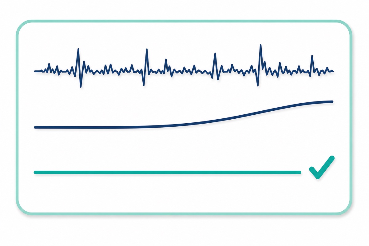
That bias is why the sketch calibrates at startup: it averages 500 gyro readings with the board held still and subtracts that offset from every later reading.
What does the complete Arduino sketch look like?
The Adafruit display stack is the only installation needed: in Arduino IDE’s Library Manager install Adafruit SSD1306 and accept the prompts for its Adafruit GFX and Adafruit BusIO dependencies. The MPU-6050 side uses no library at all — the built-in Wire reads the registers directly, so every division you just learned is visible in the code.
Two register facts drive the setup: the chip powers up in sleep mode, so we first clear the SLEEP bit in PWR_MGMT_1 (0x6B), and all fourteen data bytes sit consecutively from register 0x3B, so one burst read fetches everything.
#include <Wire.h>
#include <Adafruit_GFX.h>
#include <Adafruit_SSD1306.h>

#define MPU_ADDR 0x68        // GY-521 with AD0 left unconnected
#define OLED_ADDR 0x3C       // this 0.96" module's address
#define SCREEN_WIDTH 128
#define SCREEN_HEIGHT 64

Adafruit_SSD1306 display(SCREEN_WIDTH, SCREEN_HEIGHT, &Wire, -1);

// Sensitivity scale factors from the MPU-6050 datasheet
// (default ranges: +/-2 g and +/-250 deg/s)
const float ACCEL_LSB_PER_G   = 16384.0;
const float GYRO_LSB_PER_DPS  = 131.0;
const float ALPHA = 0.96;    // complementary filter coefficient

int16_t ax, ay, az, gx, gy, gz;
float gyroBiasX = 0;         // resting gyro offset, measured at startup
float angle = 0;             // fused tilt angle in degrees
unsigned long lastMicros;

int16_t read16() {           // one big-endian 16-bit value from the MPU
  int16_t v = Wire.read() << 8;
  v |= Wire.read();
  return v;
}

void readMPU() {
  Wire.beginTransmission(MPU_ADDR);
  Wire.write(0x3B);                      // ACCEL_XOUT_H: start of data block
  Wire.endTransmission(false);
  Wire.requestFrom(MPU_ADDR, 14, true);  // accel(6) + temp(2) + gyro(6)
  ax = read16();  ay = read16();  az = read16();
  read16();                              // skip temperature
  gx = read16();  gy = read16();  gz = read16();
}

void setup() {
  Wire.begin();

  // The MPU-6050 powers up asleep: clear the SLEEP bit in PWR_MGMT_1
  Wire.beginTransmission(MPU_ADDR);
  Wire.write(0x6B);
  Wire.write(0x00);
  Wire.endTransmission(true);
  delay(100);

  display.begin(SSD1306_SWITCHCAPVCC, OLED_ADDR);
  display.clearDisplay();
  display.setTextColor(SSD1306_WHITE);
  display.setTextSize(1);
  display.setCursor(0, 0);
  display.println(F("Calibrating..."));
  display.println(F("Keep the board still"));
  display.display();

  // Average 500 resting gyro readings to find the bias
  long sum = 0;
  for (int i = 0; i < 500; i++) {
    readMPU();
    sum += gx;
    delay(2);
  }
  gyroBiasX = sum / 500.0;

  lastMicros = micros();
}

void loop() {
  readMPU();

  unsigned long now = micros();
  float dt = (now - lastMicros) / 1000000.0;  // seconds since last loop
  lastMicros = now;

  // Raw counts to real units (divide by the scale factor)
  float ayG   = ay / ACCEL_LSB_PER_G;                // g
  float azG   = az / ACCEL_LSB_PER_G;                // g
  float rateX = (gx - gyroBiasX) / GYRO_LSB_PER_DPS; // deg/s, bias removed

  // Accelerometer tilt: stable long-term, noisy when moved
  float accelAngle = atan2(ayG, azG) * 180.0 / PI;

  // Complementary filter: gyro carries the fast changes,
  // accelerometer slowly corrects the drift
  angle = ALPHA * (angle + rateX * dt) + (1.0 - ALPHA) * accelAngle;

  display.clearDisplay();
  display.setTextSize(1);
  display.setCursor(0, 0);
  display.print(F("MPU6050 tilt"));
  display.setTextSize(3);
  display.setCursor(0, 28);
  display.print(angle, 1);
  display.setTextSize(1);
  display.print(F(" deg"));
  display.display();
}
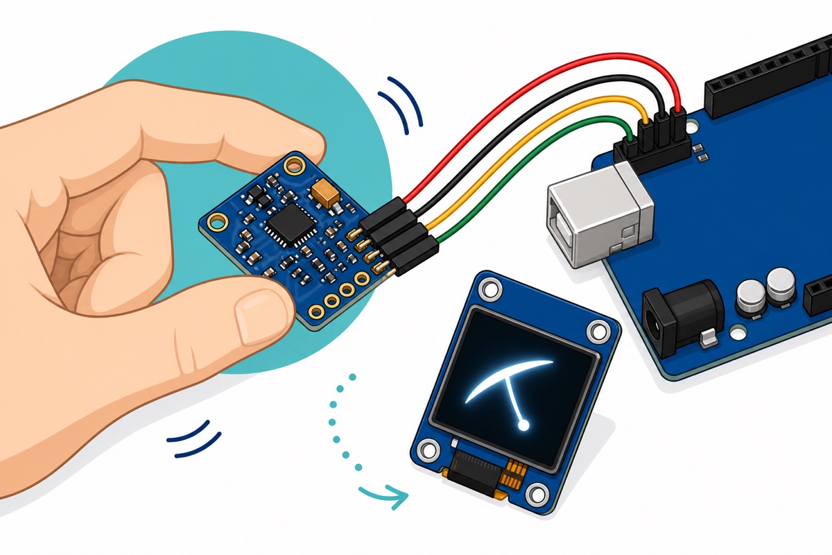
Upload, keep the board flat through the calibration message, then roll it around its X axis — the arrow on the silkscreen. The angle should track your hand instantly, settle back to zero on the desk, and stay there.
What if the readings look wrong or nothing shows up?
The GY-521 fails in recognisable ways, and each symptom points somewhere specific.
| Symptom | Likely cause | Fix |
|---|---|---|
| Nothing found on the I2C bus | Wiring or unsoldered headers | Run an I2C scanner sketch; check SDA on A4, SCL on A5, and that the header strip is actually soldered, not push-fit |
| All readings zero | Chip still asleep | Confirm the PWR_MGMT_1 write to 0x6B runs and the address is 0x68 |
| An axis stuck at 32767 or −32768 | Value railed at full scale | Momentary clipping from a sharp tap is normal; permanently railed on one axis suggests a damaged sensor |
| Angle drifts steadily while still | Gyro bias not removed | Keep the board dead still during startup calibration; reset to recalibrate |
| Angle jumps when you tap the board | Accelerometer reacting to the shock | Expected in small doses; raise ALPHA toward 0.98 to trust the gyro more |
| OLED stays blank | Reversed supply pins or wrong address | Check the GND-first header order; try 0x3D if a scanner finds the display there |
Common mistakes we see from real customers
The pattern we meet most often is wiring the Uno into XDA and XCL because the names look like SDA and SCL’s siblings. Those pads are the sensor’s own auxiliary bus — the Uno’s connection is only ever SDA and SCL.
Second is skipping the soldering: the loose header strip gets push-fitted, works flat on the desk, then cuts out the moment the board tilts and the pins shift. Solder the strip before debugging anything else.
Third is judging the module by its raw output — seeing 16384 and concluding the sensor is faulty, or dividing by a factor from a different range setting. And red-wire-first habits on the OLED’s GND-first header remain the one mistake the hardware does not forgive.
FAQ
Do I need the DMP to get a good angle?
No. The MPU-6050’s built-in Digital Motion Processor computes orientation on-chip but needs a large firmware upload and a heavier library. For tilt, the complementary filter here gives smooth, stable results with arithmetic you can actually understand.
Can the MPU6050 measure position or distance?
Not usefully, no. Position means integrating acceleration twice, so every tiny bias compounds twice over and the computed position wanders metres off within seconds — real systems add GPS, wheel encoders or cameras. Treat the MPU-6050 as an orientation sensor, not a tracker.
Why does my angle drift even when the board is still?
That is the gyro’s resting bias being integrated: every module reads slightly non-zero at rest, and summing that error grows it without limit. Calibrate at startup with the board still, and let the filter’s accelerometer term pull back the remainder.
Can I use the GY-521 with an ESP32?
Yes — wire it to the ESP32’s GPIO21 (SDA) and GPIO22 (SCL) with 3.3V on VCC and the same register code runs unchanged. Our board comparison guide helps you decide when the ESP32’s speed and WiFi are worth it.
Do I need to calibrate every time I power on?
Yes, and the sketch does it in about two seconds at startup. The gyro bias shifts with temperature and from day to day, so a stored calibration goes stale — fresh averaging at every boot costs nothing.
Last updated August 2026. Stuck? Chat with us on WhatsApp.
